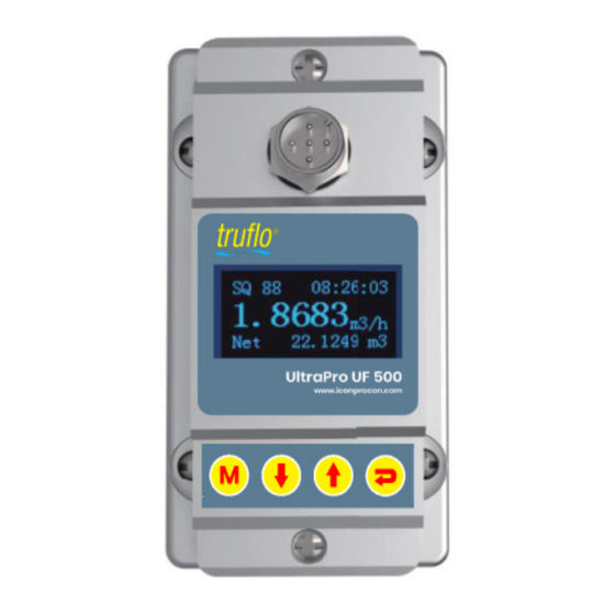
Icon Process Controls truflo Ultraflo UF500 Instruction Manual
Ultrasonic non-contact flow meter
Hide thumbs
Also See for truflo Ultraflo UF500:
- Quick start manual (19 pages) ,
- Quick start manual (14 pages) ,
- Operating manual (18 pages)
Advertisement
Quick Links
Advertisement

Subscribe to Our Youtube Channel
Summary of Contents for Icon Process Controls truflo Ultraflo UF500
- Page 1 Ultraflo UF500 Instruction Manual...
-
Page 3: Table Of Contents
Content Product Components.............1 Installation and Connection...........2 Panel Function..............3 Powering On.................3 Keypad Functions..............3 Display Descriptions...............4 Dimensions................8... -
Page 4: Product Components
Notice Thank you for choosing UF 500 Series Flow Meter. This instruction manual contains the important using and operation information of the flow meter. Please read carefully prior to operation. Components If you have any questions please cont act yo ur represe nt at ive as soon as possible. -
Page 5: Installation And Connection
Installation and Connection Step1: Step2: Make sure no di rt, pai nt, or other Align the upper bracket to the stai ns on the surface of the tube. Then pipe position. Using the mounting screws position on the underside of the pipe. connect the upper and the lower brackets together. -
Page 6: Panel Function
Panel Mounting screw OLED display screen Model Keypad Mounting screw Powering n t he self -diagnosis program G a l S i gnal Qual i ty (SQ val ue) Q value Sig nal Quality. in dicates the level of the sig n al detected. -
Page 7: Display Descriptions
escriptions Di spl ay Menu ower on display Velocit Tot al Date : 19-06-22 Time : 12 : 30 Velocity : 1.035 ft/s Flow Total Net : 723.58 Gal P ress to display Flow Rat e/ Net To t al. Press to ret urn t o previous menu. - Page 8 S e tup M e nu – P i pe Pa rame te r P re ss to d isplay: , S e lect 0 . P ipe p a ra m e t e r, t h e n Th e f o llo win g o p t io n s a re a va ila b le (using the b u t t o n s) 1.
- Page 9 6 . Syst e m I NFO System INFO: Display serial number (SN) of the meter. This SN is the only one assigned to each flow meter. Set zero: Press ; reset “Zero Point” which was set by the user. Manual Totalizer: The manual totalizer is a separate totalizer.
- Page 10 If the flow is below the cut-off the flow indication on the display will be zero. (This function can prevent the flow meter from reading flow after a pump is shut down but there is still liquid movement in the pipe, which would result in a flow total error.) Generally, 0.03ft/s is recommended to enter as the low flow cut off point.
-
Page 11: Dimensions
Dimensions D (mm) Model (mm) (mm) (mm) UF-20 1.5/Φ20 8/Φ23 UF-25 1.5/Φ25 4.5/Φ28 1.5/Φ32 4.5/Φ35 UF-32 28.5 18.5 1.5/Φ38 8.5/Φ45 UF-40 29.5 1.5/Φ48 8.5/Φ54 UF-50 1.5/Φ58 .5/Φ64 UF-63 For Additional Support Please Contact US sales@iconprocon.com | support@iconprocon.com | PH: 905.469-9283...

Need help?
Do you have a question about the truflo Ultraflo UF500 and is the answer not in the manual?
Questions and answers