Table of Contents
Advertisement
Quick Links
Advertisement
Table of Contents

Subscribe to Our Youtube Channel
Summary of Contents for Icon Process Controls Level Pro UltraPro 500 Series
- Page 1 ULTRAPRO 500 MANUAL Ultrasonic level meters ® UltraPro INSTRUCTION MANUAL...
-
Page 2: Table Of Contents
ULTRAPRO 500 MANUAL Ultrasonic level meters TABLE OF CONTENTS 1 . Safety ..................................4 2 . Packing, transportation and storage ......................4 3 . Measuring principle ............................5 4 . Range of application ............................5 5 . Features of variants ............................5 6 . Dimensional drawings ............................6 7 . -
Page 3: Safety
ULTRAPRO 500 MANUAL Ultrasonic level meters USED SYMBOLS In order to provide maximum safety of processes, we have defined the following safety and information instructions. Each of the instructions is marked with an icon. Alert, warning, danger This symbol informs about particularly important instructions for installation and operation of the equipment or about dangerous situations that may occur during installation and operation. -
Page 4: Measuring Principle
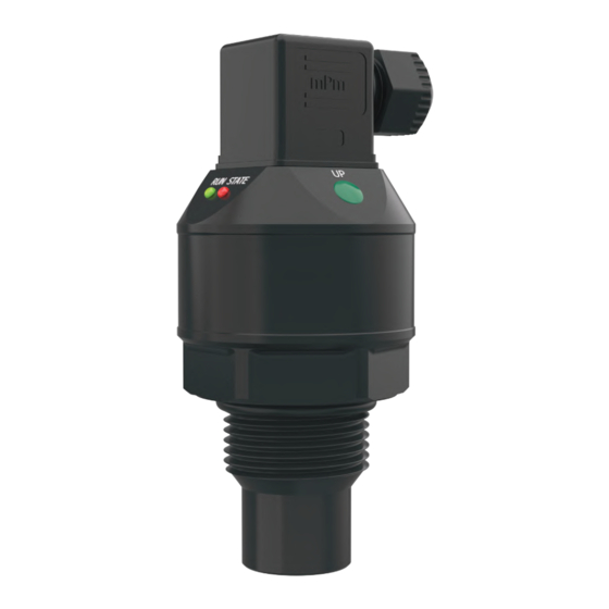
ULTRAPRO 500 MANUAL Ultrasonic level meters 3. MEASURING PRINCIPLE The UPS Series ultrasonic level sensors are compact measure-ment devices containing an electro-acoustic transducer and an electronic module. Using the electro-acoustic transducer, level meters and level sensors transmit a series of ultrasonic puls-es that spread towards the surface. The transducer then receives the reflected acoustic wave, which is subsequently processed in the electronic module. -
Page 5: Dimensional Drawings
ULTRAPRO 500 MANUAL Ultrasonic level meters 6 . DIMENSIONAL DRAWINGS UPS_–53_–01–_ UPS_–53_–02–_ UPS_–53_–06–_ UPS_–53_–20–_ UPS_–53_–10–_ ground terminal Al alloy 7 . INSTALLATION AND PUTTING INTO OPERATION This procedure includes the following three steps. Installation Electric connection Setting www.iconprocon.com | sales@iconprocon.com | 905.469.9283... -
Page 6: Installation Instructions
ULTRAPRO 500 MANUAL Ultrasonic level meters 6 . DIMENSIONAL DRAWINGS a) The device is installed in a vertical position into the upper lid of the tank or reservoir using a lug, a fastening nut or a flange in such a way that the axis of the device is perpendicular to the surface level of the measured liquid (Fig. 1). Tightening of the level meter in the welding flange (or. - Page 7 ULTRAPRO 500 MANUAL Ultrasonic level meters g) Foam may be produced on the surface of the measured liquid during filling, mixing and other processes. The thick foam significantly absorbs the ultrasound signal and may cause malfunction of the device (Fig. 5). In those cases it is necessary to test the device in advance and, if necessary, to contact the manufacturer.
- Page 8 ULTRAPRO 500 MANUAL Ultrasonic level meters k) The measuring device shall not be installed in places with direct sunlight and shall be protected against weather conditions. l) If installation in places with direct sunlight is inevitable, it is necessary to mount a shielding cover above the device (Fig.
-
Page 9: Electrical Connection
ULTRAPRO 500 MANUAL Ultrasonic level meters ventilation • If the level sensor is mounted to bottlenecks and places with holes barriers, or near uneven walls or the filling area, where the transmission signal could be distorted, we recommend using a guide tube (acoustic horn). The tube must be made from a single material with a smooth inner surface (see image 14a, 14b ). - Page 10 ULTRAPRO 500 MANUAL Ultrasonic level meters Type UPS-500_–_ _–_–S–G–_ Positive supply pole +U is BN 1 ( ) connected to the brown wire BU 2 ( ) or to connector pin 1, negative pole to the blue wire or to Fig.
- Page 11 ULTRAPRO 500 MANUAL Ultrasonic level meters Type UPS-500_–_ _–_–S–C–_ The positive supply pole +U is BN 1 ( ) connected to connector pin 1 or the brown wire of the BU (3) connected cable, the negative pole is connected to connector Fig.
- Page 12 ULTRAPRO 500 MANUAL Ultrasonic level meters Type UPS-500_–_ _–_–M–B(H)–_ Level meters designed connection to the PLC input (RS–485). positive supply pole connected to the brown wire of the connected cable, the negative pole is Fig. 26: Connection diagram of the level meter connected to the blue wire of the with an RS–485 output (variant –M) connected cable.
-
Page 13: Set-Up Elements
ULTRAPRO 500 MANUAL Ultrasonic level meters 10. SET-UP ELEMENTS "# %& "(")"*#! !"#$%&'()*& /012/0/%/0/0/0/0, !"#$%"&'()"&*$'+&,"''$-.&/,$-.&0/''1-, Valid for: UPS_-53_-_ _-_-_-_-T !"#$% "&&' 5)**>5()7 !"#$%&'(()*%+,"--,. /0%&'(()*%+,"$,. ?)5B3*C%@57>D "$'% 12!%3*4356()7%89:;:2< 12!%3*4356()7%8=/$<% /?(76@)*35%(76*@A3((>7 !"#$%&'(%)*+%,-./0%12%/3*%4*-05."6#%7*8"9*% :8*.0"16%;"/3%<5//160= !"#$%&'()*& /012/0/%/0/0/0/0+ !"#$%"&'()"&*$'+&,"''$-.&/,$-.&2&32.-"'$%&)"- Valid for: UPS_-53_-_ _-_-_-_-M *+),-% '"&&'% 5)**>5()7 2E0:F%@>*@3(3G>%67>6% +,"--,. -
Page 14: Status Signalization
ULTRAPRO 500 MANUAL Ultrasonic level meters 11. STATUS INDICATION "#"$! &'(&)#"&*' !"#$%&'%()*+, -+.+/, 0/&(*%+& %&"#'#()#*%*#'#$*+$!%,$%)-#%.#(/0"#.#$)%+$)#"1(2%(''",34%5%444%6% %7%)-#%.#(/0"#*%/0"8(9#%+/%+$%)-#%*#(*%:,$#%,8%)-#%2#1#2%.#)#"%,"%)-#% !"#$! !"##$ 02)"(/,0$*%)"($/*09#"%+/%*+"); %&&%7%)-#%2#1#2%.#)#"%+/%$,)%9('(<2#%,8%"#9#+1+$!%)-#%#9-,4%=$9,""#9)%+$/)(22()+,$%,"% .(280$9)+,$ %7%>%.?%&@%AB%)-"#/-,2*%/#))+$!%+$*+9()+,$ %7%6@%.?%&5@%AB%)-"#/-,2*%/#))+$!%+$*+9()+,$ %&&%7%/#$/,"%,0)'0)%+/%*+/9,$$#9)#*%&CDDB ,"($!# %'%7%/#$/,"%,0)'0)%+/%9,$$#9)#*%&CEB %7%/#))+$!%+$*+9()+,$%8,"%)-#%*+/9,$$#9)#*%/)()0/ %7%/#))+$!%+$*+9()+,$%8,"%)-#%9,$$#9)#*%/)()0/ 7%9,..0$+9()+,$%0$*#"%F(;%,$%2+$#%GHI>JK 12. SETTING +""&', !"#$%&'(%)*+,-./%012*%% 3.*4*.%0*,5-6*0*7/8 !" www.iconprocon.com | sales@iconprocon.com | 905.469.9283... -
Page 15: Setting Procedure For Level Meters Ups-500
ULTRAPRO 500 MANUAL Ultrasonic level meters 12 .1 . Procedure manual setting of level meter UPS Series !"#!#!#$%&''()*$+,()*$-+''.), !" /0,(1$2.3&#$%&'&%#(&!)*+&(&,-" !"##$%&'()'*(+",'*$-$#'.'-/'01'23 !"##$%&'()'455",'*$-$#'61'-/'071'23 89:#(,;'<")94*#'="##$%&= 4)5&6,&$2.3&$ www.iconprocon.com | sales@iconprocon.com | 905.469.9283... - Page 16 ULTRAPRO 500 MANUAL Ultrasonic level meters !"#!#"#$%&''()*$+,()*$-$.-*)&'(/$0&)$ !" 1-,(/$.23&#$%&'&%#(&!)*+&(&,-" !"##$%&'()'*(+",'*$-$#'.'-/'01'23 !"##$%&'()'455",'*$-$#'61'-/'071'23 89:#(,;'<")94*#'="##$%&= ." 4)5&6,&$.23& !"#$%&'(%)*+,-.,%/01,%% !" www.iconprocon.com | sales@iconprocon.com | 905.469.9283...
- Page 17 ULTRAPRO 500 MANUAL Ultrasonic level meters 12.1.2. Setting using a magnetic pen (version “M”) !" $%&'#(#)*+%,'&#%-./-.#01'2#.1'#3!453-3#+'6'+#5,#'4*''&'&" 7" $%&'#8#)%/'2#%-./-.#01'2#.1'#3!453-3#+'6'+#5,#'4*''&'&" 9:;:;9;#<'..52=#-,52=#7-..%2, !" $%&'#(#!"#$%&'($)*+)*(,-&.(*-&(/012/)/(#&3&#(2%(&1"&&'&'4 !"##$%&'()'(/"%'(.#/.# !"##$%&'()'*+(,"-'(.#/.# 01*#(23'-")1.+#',"##$%&, %&'(#) #!$+&.($)*+)*(,-&.(*-&(/012/)/(#&3&#(2%(&1"&&'&'4( www.iconprocon.com | sales@iconprocon.com | 905.469.9283...
- Page 18 ULTRAPRO 500 MANUAL Ultrasonic level meters !"#"#"#$%&''()*$+,()*$-$.-*)&'(/$0&)$ !" 123&$4$!"#$%&'($)*+)*(,-&.(*-&(/012/)/(#&3&#(2%(&1"&&'&'4 !"##$%&'()'*$+,(%%",#"*'(-#.-# !"##$%&'()',(%%",#"*'(-#.-# /0,#(12'*")0-3#'+"##$%&+ $" %&'(#) $!$+&.($)*+)*(,-&.(*-&(/012/)/(#&3&#(2%(&1"&&'&'4 !"#$%&'!"()%$$"(%'!"*+)'&(),%**)-")%&'.."//%-*")0&!%*)!1")*"2"*)*"'2"/)!1")("'()34&"5 67)&4)-0!!4&)%/)8#"//"()%&)!1")/"!!%&9)$4("),%!1%&):;)/<)!1")$"'/0#"$"&!)$4(")47)!1")*"2"*)$"!"#),%**)-") #"/!4#"(5)=1")&",*+)/"!)2'*0"/),%**)&4!)-")/'2"(5 www.iconprocon.com | sales@iconprocon.com | 905.469.9283...


Need help?
Do you have a question about the Level Pro UltraPro 500 Series and is the answer not in the manual?
Questions and answers