Table of Contents
Advertisement
Quick Links
Advertisement
Table of Contents

Related Manuals for OPTO-EDU A63.7080


Summary of Contents for OPTO-EDU A63.7080
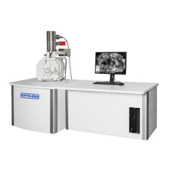
- Page 1 A63.7080/81 Scanning Electron Microscope (SEM) Instruction Manual...
-
Page 2: Table Of Contents
1.1 General Description 1.1.1Features of A63.7080/81 Scanning Electron Microscope A63.7080/81 Scanning Electron Microscope (A63.7080/81 for short) is a large- scale, high precise electron optics instrument used to research microscopic structure sof objectives. It receives the stimulated electron signals and forms images by focusedelectron beam scanning on the specimen surface spot by spot. - Page 3 can be accurately performed. 5. Simple operation: users can perform main scan after receiving short-term training. 6. Electronics and computer science can appropriately improve image quality. For example, the image processing modulator can improve the blackness and contrast of the image to appropriately improve the brightness of each part of the image. 7.
- Page 4 At the same time, the application of SEM Rapid changes in the field of human survival, such as biology, Environmental protection and medicine. 1.3ProductnameandItsmodel Product name: Scanning Electron Microscope Productmodel:A63.7080/81 1.4SpecificationandItsMeaning A63.7080/81 Seriescode Modelcode...
- Page 5 1.5 Key technical performance indicators Resolution: SE 1.5nm@15kv BSE3nm @ 30kv Magnetization: 8 times~800,000 times Electronic clamp: Schottky field emission electron gun Accelerating voltage: 0~30kV Lens system: Electromagnetic lens Objective lens aperture: Three holes optional (the position can be adjusted outside the vacuum) Chamber : Six switches connected to two interfaces (1) Displacement of the standard manual sample stage: X = 80mm, Y = 60mm, Z = 50mm, T = -5°~+90°, R = 360°...
- Page 6 1.7.1 Room requirements A63.7080/81 is required to be installed with strong load-bearing capacity (floor load ≥ 246500 Kg/m2) and shockproof effect is better in the independent laboratory. 5 The instrument installation room should be able to block the light, part of the work needs to be in the darkroom.
- Page 7 A63.7080/81. It is the user's responsibility to provide a relatively "quiet" environment for A63.7080/81. If it is found that the sound in the installation environment affects the scanning electron microscope image, the user is responsible to take measures to correct it.
-
Page 8: Structure Feature And Operating Principle
Finally, the computer receive the signal and form a image. The main structures of A63.7080/81 are electron optics column, chamber, automatic vacuum system, electronics and display console, etc. - Page 9 2.2 Electron Optics Column A63.7080/81 electron optics column can produce and focus electron beam to form a fine spot on specimen. The electron optics column consists of Schottky field emission electron gun, electromagnetic beam alignment system, column isolation valve (V1), objective lens, scanning coil assembly, stigmator and electron detector.
- Page 10 The electromagnetic beam alignment system is adopted to ensure coincidence of electron beam and the optical axes. A63.7080/81 adopts two sets of electromagnetic alignment coils to form the electromagnetic alignment system, which can be conveniently adjusted by the control software to make the electron beam coincide with the optical path axis.
- Page 11 2.2.7 A63.7080/81 accessories Standard accessories which can be installed on A63.7080/81 are X-Ray Energy Dispersive spectrometer (EDS), X-ray wave dispersive spectrometer, 10 Cathodoluminescence spectrometer, etc. Currently, EDS is the most popular accessory of SEM. EDS consists of detector and analysis system, which can realize the identification and quantification of the specimen.
- Page 12 sample size: Ф175 mm ; Maximum sample height: 40mm 2.3.3 Five axis automatic medium size specimen stage (optional) Horizontal: X=80mm Y=50mm Vertical: Z =30mm Tilt= -5° ~ +70° Rotation = 360° Maximum sample size: Ф175 mm ; Maximum sample height: 20mm The sample locking device can be used to lock the sample stage and sample chamber after the sample stage is inserted to reduce the influence of vibration.
- Page 13 5. Various valves are used for vacuum partition. e.g., V1 can separate electron gun from chamber; when the chamber is venting, the electron gun can keep in vacuum state; V2 is used to acquire vacuum between chamber and mechanical pump . When the specimen chamber meet the starting requirements of the molecular pump, the V2 is opened and molecular pump is started to make the system obtain a high vacuum.
- Page 14 2.5.1 Electronics Console Electronics console includes circuit boards with various functions and power supplies. It is controlled by software manually. The Electronics console of A63.7080/81 includes three parts: the scanning electron microscope control electrical system, the vacuum power supply and the high voltage power supply.
-
Page 15: Scanning Control Window Of A63.7080/81
3. Scanning Control Window of A63.7080/81 3.1 computer operating system A63.7080/81 operating software is installed on the Windows operating system and follows the usage habits of the Windows operating system. 3.2 operating system The SEM operating software icon is shown in Fig. 3-1. Double-click the icon to open the user interface, as shown in Fig. - Page 16 -Beam -Align (page 2-14) -Image (page 2-15) -Aux (page 2-16) -Status (page 2-17) Set the astigmatic set the scan area Set the external scan signal Display working voltage, high voltage error code and operation log of different parts Main Field(page 2-18) Set contrast brightness, focus, magnification, scan rotation Status Field Displays the vacuum and beam values Table 3-4 main functions of scan control window Instructions on mouse operation: After clicking the slider on the toolbar, drag the mouse to fine tune the...
- Page 18 3.2.2 Get started 1. Operating the electron microscope operating software A63.7080/81; 2. Click the "SE" button in the upper right corner of the control interface to load the power of each system...
- Page 19 1. Click the "vacuum" button; 2. Wait for all function indicators to go off; 3. Keep the A63.7080/81 software on; In this state, the software system will automatically detect and record the operation parameters of the electron microscope. Fig.3-6 Click the "vacuum" button to stop using 3.2.4 Function button...
- Page 20 Fig.3-7 The function button and state display of the scan control window...
- Page 21 3.2.5 Electron beam options-vacuum control and gun control Fig.3-8 vaccum control and gun control As shown in Fig.3-8, Vacuum control and electron gun control are mainly divided into three modules: (1) Vacuum control area The "pump" button is used for automatic vacuuming of the system.
- Page 22 one. When the acceleration voltage is adjusted, the gun lens voltage will be loaded automatically. "Cold start" and "hot start" are used to start the gun. If there is no special case, the gun can not be closed after starting. "Auto return": close the gun;(this function should be used with caution) (3) Error zone High voltage error: green is normal;...
- Page 23 Special note: the values of filament current and extraction electrode must be set 23 strictly in accordance with the factory default value, especially the filament current, forbidden to adjust. 3.2.6 Electrical alignment options Fig.3-10 Electrical alignment (1) adjustment mode: click the slider with the left mouse button to make various adjustments.
- Page 24 3.2.7 Image electrical displacement Fig.3-11 electric displacement adjustment Drag the slider to adjust the electrical displacement of the image. Click once to display green for fine tuning; Click twice for bold and display in red.
- Page 25 Reset: reset the electrical displacement. Tilt compensation: according to the tilt Angle of the sample stage, the scanning error is compensated. 3.2.8 Grid and Status 3.2.8.1Grid Grid: Represents the grid voltage, fixed at 300V, no adjustment 3.2.8.2 Status ...
-
Page 26: Automatic Sample Stage
4. Automatic sample stage 4.1Sample stage control interface... - Page 27 Sample Stage Control: the sample stage can be controlled by Trackball control and 28 mouse control, which respectively control the sample moving in X, Y, Z, T and R directions. Scanning Stage Control Panel: control the movement of the sample stage. Scan Area Panel can set different rows, columns, magnification, splicing into an image;...
- Page 28 send out an alarm. This function is to prevent the sample from touching lower pole piece 4.2 Sample stage control panel (1)status (2) Input values in the box in each direction to drive the movement of the sample stage.
- Page 29 X direction: samples move in the screen horizontal direction, unit for μm; Y direction: samples move in the screen vertical direction, unit for μm; Z direction: samples move in the vertical direction, is used to adjust the working distance, unit for mm; T direction: samples tilt Angle, unit for degrees;...
- Page 30 The first click sets the beginning of the line, and the second click sets the end. At the end of the second click, the sample stage will be rotated to make the lines drawn in the image Acquisition window horizontal. If you keep the Shift key pressed during the second click, the line will be turned vertical.
- Page 31 Function: The Main tab of the Stage Control panel contains a table with a set of preset positions. By double-clicking a line, the stage will be moved to the corresponding position. 4.3.1Main Tab Editing Mode If the Main Table editing mode checkbox is activated in the Setup tab, the Main tab will display additional buttons for changing the table values: Fuction: In Main Table editing mode, the values in the Main tab as well as the values in the Position Table tab can be modified.
- Page 32 the additional functions in the Main tab when using Main Table editing mode 4.3.2 Stage Control Position Table Structure: The following figure shows the Position Table tab of the Stage Control panel with its components. Function: The following table contains information on the components of the Position Table tab:...
- Page 33 4.3.3 Stage Control Setup Structure: The following figure shows the Setup tab of the Stage Control panel with its components...
- Page 34 Function: The following table contains information on the components of the Setup tab: 4.4Scan Area Settings 4.4.1 Scan Area Structure: The following figure shows the Settings tab of the Scan Area panel with its components.
- Page 35 Function: The following table contains information on the components of the Settings tab:...
- Page 36 4.4.2 Scan Area Protocol Structure: The following figure shows the Protocol tab of the Area panel Function: In the Protocol tab, all events of an area scan will be recorded. 4.5 Image Acquisition 4.5.1 Software Interface The software control interface is shown in Fig.3-13, including menu bar, toolbars, image display area and scan control area.
- Page 37 Fig.3-13 software control interface 4.5.2 Scan Processing In the process of adjusting the image, click the right mouse button in the image area to see the interface as shown in Fig.3-14. Click the corresponding options to make relevant Settings. Click "Settings" to set the detector type, scan speed, synchronization mode, etc., as shown in Fig.
- Page 38 4.5.3 File management menu (1) Click "file (F)" in the menu bar to save or print the image, as shown in Fig.3-16. Fig.3-16 Save image files (2) There is a shortcut to save the image in the toolbar, as shown in Fig.3-17, and the storage location can be selected.
- Page 39 Fig.3-19 scan shortcut (2) Software provides a number of quick scan button, can be personalized Settings; Right - click each icon, you can set the corresponding Settings;...
- Page 40 Signal source can be selected, SE or BSE; Scanning speed: the corresponding scanning speed can be selected, the smaller the value, the faster the scanning speed; Resolution: the proportion, width and height of the image can be set; Scan cycle: line average and frame average can be set;...
- Page 41 (4)BSE image acquisition Click the shortcut of BSE image with the left mouse button, and a four segment scan window will appear. Each scan window corresponds to a signal source. You can right-click to set the correlation scan, and the signal source can select BSE1-BSE4; The brightness and contrast of BSE images can be adjusted.
-
Page 42: Sem Operating Procedure
"OFF" position. 5.1.3Panel installed correctly Before using A63.7080/81, it is necessary to check whether the panels and plate of A63.7080/81 main engine and electric cabinet are installed firmly, so as to avoid the... - Page 43 5.1.4 Do not have person moving around behind the main engine and electrical cabinets while working While using A63.7080/81, do not have person walking around behind the main engine and electrical cabinet, avoid touching the cables and pipeline, which may cause personal danger or damage to the instrument.
- Page 44 Turn on Computer, (computer password: OPTOEDUfesem) Start electron microscope software: A63.7080/81, observe the vacuum value (located at the lower right of the software) At the same time, in the "vacuum diagram" of the "advanced Settings", you can observe whether each valve is normal and the green color is open.
- Page 45 6. After starting the software each time, check whether there is any error code. Under normal circumstances, it will be displayed in green. If it is yellow, then click the clear error button on the right. After checking the high voltage, whether the load is normal, if not, the direct load can be.
- Page 46 large. Larger samples can be observed at a large lowworking distance. 5.2.2.3 Vacuum the sample chamber Click "air extraction" on the software interface, and the vacuum system will automatically vacuum the sample chamber. When the vacuum of the sample chamber 48 reaches the preset vacuum state, open the V1 valve and the instrument can start operation.
- Page 47 Final aperture alignment adjustment: in the actual use process, in order to obtain a better image, need to adjust final aperture alignment. Click the wobbler button on the software control interface (the selection function can be used). If the image moves on the screen, it indicates that the final aperture is not well aligned and needs to be adjusted.
- Page 48 3. Adjust the two knobs of the final aperture respectively to minimize the displacement or movement of the image. First adjust one knob to make the move smaller, then adjust another.
- Page 49 4. Select the high magnification to 1500-3000x and click the wobbler button to watch the image movement. Adjust the two knobs of the final aperture respectively to minimize the displacement or movement of the image. 5. If the magnification is high, you can continue to increase the magnification and fine-tune the final aperture for better results.
- Page 50 Aperture replacement: rotate the radial knob of the aperture rod of the objective lens (rotate clockwise to go in and counter-clockwise to go out), to make the indicator line corresponds to the corresponding position, and then adjust the axis of the newly replaced final aperture according to the steps of adjusting the alignment of the final aperture.
- Page 51 3. astigmatism adjust method: Adjust the magnification to 3000-5000x, select a feature point with ROI selection, and set the scanning speed to 64; (unlike the alignment of final aperture, the scanning speed here is slow) Focus the image to the clearest, then adjust astigmatism.
- Page 52 5.2.4.4 Adjust the electrical alignment The electron beam can be modulated in the electrical alignment. When the filament works for a while, the electron beam may have some deviation. Some corrections can be made by adjusting Beam tilt and Beam shift in the software. (this feature does not need regular adjustment) Make ensure that the alignment of final aperture is normal;...
- Page 53 5.3 Monitoring and recording in operation 5.3.1 Working conditions of vacuum system A63.7080/81 vacuum system is fully automatic control, the operator should be in strict accordance with the procedure started, pumping air into vacuum state, if fully automatic process is terminated, or long time cannot achieve high vacuum, or in the process of A63.7080/81 work interlock protection caused by low vacuum, operation...
- Page 54 (2) turn on the main electric power supply and computer/monitor power supply; (3) open the " A63.7080/81" software and observe the vacuum value (located at the lower right of the software); 4) at the same time, in the "vacuum diagram" of the "advanced setting", observe whether each valve is normal and the green color is the open status.
-
Page 55: Maintenance During Operation
(3) shut down the mechanical pump, shut down the air compressor. 4) only ensure that the power supply of the ion pump is supplied through the UPS power supply (in the case of power failure, the UPS power supply can be maintained for 3-4 days at most when the ion pump is only running) (5) start up smoothly after the long holiday. - Page 56 mounting seat to ensure good contact. 7. Install the stage, and press chamber button to pump the vacuum. 6.1.2 Cleaning of Final Aperture Assembly After working for a long time, the Final Aperture Assembly may be polluted, and probably lead to decline the imaging quality. It is needs to clean this part.
- Page 57 5. Remove the top column and small spring of the fixed diaphragm and place it in alcohol for 20 minutes with ultrasonic cleaning. 6. Dry the top column and small spring of the fixed diaphragm with a hot air blower and place it on a clean, lint-free cloth.
- Page 58 diaphragm; if there is a platinum pot, you can also put the diaphragm into the platinum pot or the white gold boat (or use the tweezers to clamp the edge of the diaphragm, as shown in Figure 5-3 ), the front side of the pupil (glossy side) is heated upwards with an alcohol lamp to a slight redness, and the dirt on the visible light ray 60 changes from yellow to black, and then gradually disappears.
- Page 59 The maintenance workof A63.7080/81 also includes cleaning the liner, cleaning the scanning coil, cleaning the pole piece under the objective lens and the entire electronic optical column , or moving the A63.7080/81 to another place. Such maintenance work must be done by professional engineers appointed by the manufacturer or engineers authorized by the manufacturer and specially trained and certified by the manufacturer.
-
Page 60: Transportation And Storage
6.4Long-termparkingmaintenance If you do not use A63.7080/81 for a long time, you should turn off the electron gun and keep it in a shutdown state. 7. Transportation and storage 7.1Attention in hoisting and transportation In the process of hoisting, handling and transportation, A63.7080/81 should prevent inversion, rain and strong shock, prevent cold and insolation. - Page 61 4. In the process of unpacking, it should be handled carefully to avoid contamination, damage or destroy 5. In the process of unpacking, check the packing list of A63.7080/81 products in time to avoid the loss of parts 8.2 Examination content...
- Page 62 Fully automatic ultra-high vacuum system (ionpump2,molecularpump1,mechanicalpump1) Deliveryconsumables attachmen Deliveryspecialtools attachmen attachmen accessories attachmen others Delivery documentation Packingl ist manufacturer certificate Instruction manuals electronicve rsion Operating software CD category Name specification count φ32 specimen Cup φ13 Specimen cup Delivery Tungsten single Oneinstalled consumables crystal filament...
-
Page 63: Other
polishing paste internal hexagonal wrench tweezers Delivery screwdriver special tools overshot Aperture discharging Cleaning kit Vent nozzle Clean nitrogen (φ10) accessories pipe (φ30) Hose clamps SANTAKC unremittingpower XFLASH630M 1 others Backscatter detector 8.2.2 Instrument appearance inspection Under the condition of sufficient light, the instrument should be visually free from large scratches and stains. - Page 64 User Training Report, so that the user can master the basic operation of the sample and the simple maintenance of the instrument. After the training, the user signs the report and handed it over to the OPTO-EDU installer to bring it back to the company for filing.
- Page 65 Web: www.optoedu.com 9.2 User feedback In order to improve product quality, OPTO-EDU conscientiously implements the ISO9000 quality system improvement requirements. After the installation, acceptance and training of the instrument, please fill out the “Customer Satisfaction Information Questionnaire” and sign it.。...