Table of Contents
Advertisement
Quick Links
Advertisement
Table of Contents

Related Manuals for OPTO-EDU A63.7069


Summary of Contents for OPTO-EDU A63.7069
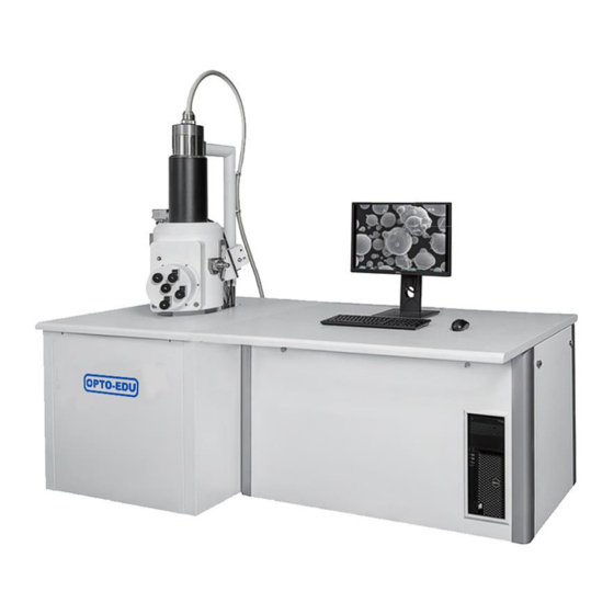
- Page 1 A 6 3 . 7 0 6 9 Tungsten Filament Scanning Electron Microscope, SED+BSDE+CCD, 8x~300000x Instruction Manual To ensure the safety and obtain satisfactory performance, please study this instruction manual thoroughly before start to use your instrument. - 00...
-
Page 2: Table Of Contents
1. Getting Started ..........................4 1.1. General Description......................4 1.1.1. Features of A63.7069 Scanning Electron Microscope ..........4 1.1.2. Main Purpose and Scope of Application ..............4 1.1.3. Product Name& Model ............错误!未定义书签。 1.1.4. Using Condition ....................... 5 1.1.5. Influence on Environment and Energy Sources ............6 1.1.6. - Page 3 3.7.4. Line Scanning ......................28 3.7.5. Spot Scanning ......................28 3.7.6. Multi Channels ...................... 29 3.7.7. Scanning Speed ..................... 29 3.7.8. Scanning Resolution ....................29 3.7.9. Snapshot ........................ 29 3.7.10. Synchronous Record ....................29 3.7.11. Photo Preview ....................... 30 3.7.12. Parameter Setting ....................30 3.8.
- Page 4 4.4.11. Edge ........................38 4.4.12. Emboss ........................38 4.5. Rotate Left and right ..................... 39 4.6. Set Rotation ........................39 4.7. Re-sample: Image Magnification .................. 39 4.8. Alpha Channel ....................... 39 4.8.1. Opacity ........................39 4.8.2. Remove........................39 4.9. Gray Scale ........................39 4.10.
-
Page 5: Getting Started
1.1. General Description 1.1.1. Features of A63.7069 Scanning Electron Microscope A63.7069 Scanning Electron Microscope (A63.7069 for short) is a large-scale, high precise electron optics instrument used to research microscopic structures of objectives. It receives the stimulated electron signals and forms images by focused electron beam scanning on the specimen surface spot by spot. -
Page 6: Product Name& Model
Meanwhile, the application of SEM are changing rapidly in the fields of human survival and development, such as biology, environmental protection and medicine. 1.1.3. Product Name & Model Product name: Scanning Electron Microscope Product model: A63.7069 1.1.4. Using Condition 1.1.4.1. Environmental Condition Temperature change ≤1℃/h Temperature 16℃-25℃... -
Page 7: Influence On Environment And Energy Sources
Influence on Environment and Energy Sources ❖ The X-ray radiations conform to the national standard and will not influence environment and energy sources. 1.1.6. Safety ❖ The safety of A63.7069 conforms to the requirements of the national safety standards of instruments. - 06... -
Page 8: Structure Feature And Operating Principle
1.2.2. Electron Optics Column A63.7069 electron optics column can produce and focus electron beam to form a fine spot on specimen. The electron optics column consists of electron gun, electromagnetic beam alignment system, dual condenser lenses, column isolation valve (V1), objective lens, scanning coil assembly, stigmator and electron detector. - Page 9 A positive 12KV potential biased on the scintillator accelerates SE. The photon produced by scintillator enters into the window of photomultiplier, and output video signal. 1.2.2.9. Accessories ❖ Standard accessories which can be installed on A63.7069 are X-Ray Energy Dispersive spectrometer (EDS), X-ray...
-
Page 10: Specimen Chamber And Specimen Stage
1.2.3. Specimen Chamber and Specimen Stage ❖ The specimen chamber is mounted to the vibration isolated frame. Vacuum system is installed under chamber, which electron optics column is installed above chamber. The specimen stage is installed in the front of chamber. Vent of chamber will not influence vacuum status of other parts. - Page 11 The automatic vacuum system mainly includes Turbo Molecular Pump, Mechanical Pump, Cold Cathode Gauge, connecting pipeline, damping device, various valves, and various gauges etc. More details are as follows: ❖ Turbo Molecular Pump is used to acquire high vacuum for the system. ❖...
-
Page 12: Electronics And Display Console
Electronics and display console consists of electronics console, computer system , which is used to control various functions of A63.7069, observe image of specimen and take photos, etc. The main switch on the control console is the switch of the vacuum system. The switch on the main frame is the switch of Electronics Console. -
Page 13: Technical Index
Image output: Support various image format output and printer output, BMP, JPG, TIFF, TGA, PNG. (*.sem, special format, can be used in Image processing software.) ❖ Auto function: auto-focus, auto-brightness/contrast, auto-stigmator, auto-filament. ❖ High performance computer, Windows system, USB2.0 communication interface. A63.7069 SEM control software, SemIamge (optional). ❖ Main frame size: 800*800*1380(mm) ❖... -
Page 14: Operation Procedure
2. Operation Procedure 2.1. Start up Procedures ❖ Turn on Mechanical pump and Air compressor (make sure V1 is closed). The pressure of compressor should over 4kgf/c m (0.4MPa). ❖ Turn on Main switch and Main frame switch. ❖ Switch “AUTO/MAN” to “AUTO” at the vacuum control panel which has been installed in the rear part of Main frame. -
Page 15: Operation Of Acquire An Image
2.2. Operation of Acquire an image ❖ Open V1, indicator lamp is on. ❖ After V1 is on, the Contrast scrollbar turns into adjustable status. About 2s later, HV, Bias and Filament turn into adjustable status. ❖ Adjust HV slowly, especially over 10KV. Generally, for the sample which has good electrical conductivity, HV can be adjust to the range of 20-30KV;... - Page 16 ❖ Adjust Filament current The range of filament current is 0 – 3A. User can drag the slider to adjust the filament current. When the current value increased to about 2A, the display of Beam Current begin to increase slowly. When the current over 2.3A, please increase the filament current slowly, and pay attention to observe the image at the same time.
-
Page 17: Specimen Changing Procedures
2.3. Specimen Changing Procedures ❖ Click the [OFF] button, the value of HV, Bias, Filament and Contrast will return to zero. ❖ Close V1, click the [Chamber] button, the color of button will change to YELLOW, V4 will be opened. About 3-5 minutes later, pull out sample stage, change a sample, push the stage in, click the [Chamber] button again, the color of Chamber button will change to grey, system will pump the low vacuum, and the vacuum value will displayed on control panel. -
Page 18: Filament Changing Procedures
2.4. Filament changing procedures ❖ If the screen turn to black suddenly and the indicator of filament value return to zero, that means filament is broken, it’s time to change a new filament. ❖ Click the [OFF] button, the value of HV, Bias, Filament and Contrast will return to zero. ❖... -
Page 19: Sem Shutdown Procedures
2.5. SEM Shutdown Procedures ❖ Click the [OFF] button, the value of HV, Bias, Filament and Contrast will return to zero. ❖ Close V1. ❖ Click the [Start] button, the color of Start will turn Grey. ❖ Close the software and shutdown the computer. ❖... -
Page 20: Scanning Control Window Of A63.7069
3. Scanning Control Window of A63.7069 ❖ Double click the icon on the desktop, will start the software. ❖ The scanning window mainly includes title bar, menu bar, shortcut toolbar and three areas: Scanning Area, Thumb and log Area, Control Panel Area. -
Page 21: Control Panel
Control Panel - 20 -... -
Page 22: Vacuum And Hv
3.3.1. Vacuum and HV ❖ Start: Click the button, its color will turn red, the vacuum system will start automatically; click it again, its color will turn gray, software will shut down the vacuum system. Manual operated V1 valve can not be opened or closed by the vacuum system, it should be operated manually; pneumatic operated V1 valve will be automatically closed when the Start button grey. -
Page 23: Bias Control
3.3.3. Bias control ❖ Gun bias is the voltage between filament and wehnelt cap, which is used to confine the emission current of electron gun and stabilize the emitted electron numbers. ❖ Drag the scroll bar of [Bias] on panel with mouse can control the value of bias. The adjustment range of Bias is 0-30KV, recommended less than 300V;... -
Page 24: Brightness And Contrast
filament current should not be increased, otherwise, the service life of filament may be shortened. ❖ Pay attention to the speed of adjustment in order to prolong the filament’s service life. It is suggested that at the range of 0A to 2A, the speed of filament adjustment should be controlled lower than 0.25A/s;... -
Page 25: Objective Lens
not be changed. ❖ Click the [Condenser Lens Reversal Switch] button shortcut toolbar, the state of reversal switch of condenser lens can be changed (on or off). 3.3.8. Objective Lens ❖ Dragging the scroll bar of [Objective Lens] on panel with mouse to control objective lens. It is divided into coarse, fine and tiny adjustment. -
Page 26: Scan Shift
3.4.11. Scan Shift ❖ Clicking the [Scan Shift] button on panel can start the Scan Shift adjustment. The Scan Shift control contains a box area, two scroll bars and a display label. ❖ Dragging horizontal and vertical scroll bar of [Scan Shift] with mouse can control scan shift. Dragging leftward or rightward can change value in X direction, and dragging upward and downward can change value in Y direction. -
Page 27: Stigmator
3.4.13. Stigmator ❖ Coil of stigmator is installed in scanning coil assembly. The function of stigmator is to correct elliptic electron spot caused by aperture pollution or other distortions of lens magnetic field. The stigmator can correct astigmatism rapidly and easily. ❖... -
Page 28: Thumb Panel
3.5. Thumb Panel ❖ Acquire an image or open a saved image will display in this area. ❖ Check [Select All] will select all the thumbnail. ❖ Save: Select the thumbnail image, click the [Save] button can save the image file. Click Ctrl and click the thumbnail image can save multiple image files. -
Page 29: Scanning Operation
3.7. Scanning operation 3.7.1. Freezing ❖ In this mode, the image in scanning area has been “frozen”, and will not be updated. ❖ Clicking menu [Scan > Freeze] or clicking the [Freeze] button on shortcut toolbar can freeze the current scanning image. 3.7.2. -
Page 30: Multi Channels
3.7.6. Multi Channels ❖ In this mode, two kinds of live images are displayed side-by-side in the Scanning Area. The signal of each image is gotten from the same scanning area of specimen, but two different detectors. For example, SE image is displayed on left side, while BSE is displayed on right side. -
Page 31: Photo Preview
3.7.11. Photo Preview ❖ Clicking menu [Scan > Photo Preview] can preview the photos to be saved. 3.7.12. Parameter Setting ❖ Clicking menu [Tools > Options > Common] or clicking the [Options] button shortcut bar can open the [Options] dialog box . ❖... -
Page 32: Auto Focus
3.8.2. Auto Focus ❖ Clicking menu item [Auto > Auto Focus] or clicking the [Auto Focus] button on shortcut toolbar can automatically adjust focal length of objective lens, identify focused image. ❖ During the process of automatic adjustment, press the [ESC] key can escape this function. ❖... -
Page 33: Actual Size Of Image
3.9.3. Actual Size of Image ❖ Clicking menu [Image > Actual Size] can display the image in scanning area in proportion of 1:1. 3.9.4. Fit Window ❖ Clicking menu [Image > Fit] or clicking the [Fit] button window on shortcut toolbar can display the image in the scanning area with fit window. -
Page 34: Oscillograph
❖ Add U-Scale function can add multi U-Scale, clicking the button on shortcut toolbar can start it. 3.9.9. Oscillograph ❖ Clicking menu [Image > Oscillograph] or clicking the [Oscillograph] button on shortcut toolbar can show or hide digital oscillograph. ❖ This function is used to real-time display waveform of input signal. -
Page 35: Language And Other Parameter
3.10.3. Language and Other parameter ❖ Clicking menu [Tools > Options > Others] can open the Debug box. ❖ Language: The software provide Chinese Simplified and English to choose. ❖ Prior Save Type: User can select different file format to save. ❖... -
Page 36: Digital Image Processing Window
4. Digital Image Processing Window ❖ This window includes processing and analysis methods of various images and some practical image operation. It can save the images as new file. ❖ Clicking the [Return] button on shortcut toolbar can return to scanning control window. -
Page 37: Negative
4.3. Negative Source Negative 4.4. Filters 4.4.1. Set Threshold Source Setting threshold 4.4.2. Colorize Source Colorize 4.4.3. Lighten Source Lightening 4.4.4. Darken Source Darken - 36 -... -
Page 38: Contrast
4.4.5. Contrast Source Adding contrast 4.4.6. Erode Source Erode 4.4.7. Dilate Source Dilate 4.4.8. Blur Source Blur - 37 -... -
Page 39: Soften
4.4.9. Soften Source Soften 4.4.10. Sharpen Source Sharpen 4.4.11. Edge Source Edge 4.4.12. Emboss Source Emboss - 38 -... -
Page 40: Rotate Left And Right
4.5. Rotate Left and right Source Rotate left Rotate right 4.6. Set Rotation Source Rotate in arbitrary angle 4.7. Re-sample: Image Magnification Source After re-sampling and zoom 4.8. Alpha Channel 4.8.1. Opacity Source After Opacity 4.8.2. Remove ❖ It is only applicable to color image. 4.9. -
Page 41: Dither
4.10. Dither - 40 -... -
Page 42: Increase Bpp And Decrease Bpp
4.11. Increase Bpp and Decrease Bpp ❖ Only used in image storage, and the default set of image is optimal, it is not recommended to change. 4.12. Split Channels 4.12.1. Split to RGB Source After splitting according to three primary colors 4.12.2. -
Page 43: Pseudo Colors
4.12.4. Pseudo Colors Source Pseudo Colors 4.13. Options - 42 -... -
Page 44: Operating Rules
5. Operating Rules ❖ This chapter includes the following contents: operation precautions, vacuum operation in manual mode, final aperture alignment and selection, astigmatism correction, operation of the specimen stage. 5.1. Precautions In order to avoid stoppage of instrument, the instrument is provided with protective interlocking equipment. -
Page 45: Final Aperture Alignment And Selection
panel manually, lamp of V3 will be turned on. ❖ Wait until the vacuum display reaches over 8.0*10 Torr again, press the “TMP ON” button at the vacuum control panel, the lamp of TMP will be turned on, vacuum system come into the high vacuum working status. - Page 46 2. Focus the image by adjusting the coarse button, and observe the movement of this point between the focus and defocus. 3. Adjust the knobs of final aperture holder in two directions to make sure the “characteristic point” do not move or move the smallest, when focusing or defocusing. ❖...
-
Page 47: Final Aperture Selection
❖ Focus the image, the characteristic point move away its original position along another direction, adjust another knob of final aperture holder, and make this point move back to its original position. Repeat this step, until this point almost stay in the original position when focusing or defocusing. - Page 48 2. If all the parameters of SEM is correct, and the alignment of final aperture is well, astigmatism correction is adjustable in range, but the system can not acquire a clear image, it is need to change an aperture. Note: If the astigmatism correction is out of range, it is suggested to change another aperture. When check the astigmatism, it better to use the sample with well conductivity.
-
Page 49: Astigmatism Correction
5.4. Astigmatism Correction ❖ When observe image at high-magnification (e.g. 3000X-10KX), the alignment of final aperture is in well adjustment, but the user also can not acquire a clear image. ❖ Making the image to be over or under focus, if the “characteristic point” on image is stretched in two perpendicular directions, there must be astigmatism which needs to be corrected. -
Page 50: Operation Of The Specimen Stage
6. It is necessary to focus the image, when after finished the astigmatism correction. Note: For users’ convenience, adjusting stigmator can operate as follows: move the mouse on collected image, press right button and drag. Dragging in horizontal direction can change X value, dragging in vertical direction can change Y value. -
Page 51: Specimen Grounding Alarm
Note: WD is the distance when the image is clearest. After adjust the movement of Z direction, focus the image. When the image is clearest, the display of WD is the real value. ❖ Rotation of specimen stage: Rotate the knob R in the stage, the specimen holder can rotate at any degree from 0 to 360 ❖... -
Page 52: Accessories
6. Accessories 6.1. CCD 1. CCD camera is used to observe the inside of the specimen chamber, mainly used to monitor the position of the sample, convenient for workers to operate, while avoiding the damage to the sample or the pole shoe caused by misoperation. 2. - Page 53 2. Operation steps ❖ After installing the backscatter detector correctly, press the Power button, the button will turn red. ❖ Clicking menu [Image > Multi Channels > Dual Channels] can start the dual channel image display mode, the capture window is shown below. By default the left side is channel one (secondary electron image) and the right side is channel two (backscatter image).
-
Page 54: Maintenance
7. Maintenance ❖ Normally, the user can not open the cover plate, in order to avoid the damage to operator. ❖ Without the guidance of the engineer, the user can not move the position of the SEM, in order to avoid the damage to instrument. ❖... - Page 55 Note: Hold on the GUN, pull off the wehnelt cap assembly in an axial direction. 3. Dismantle the broken filament. ❖ Use special tool counterclockwise rotate the crimp ring, then the filament can be dismantled. 4. Clean and polish wehnelt cap, if it is very dirty. ❖...
-
Page 56: Replacement Of Scintillator Of Se Detector
❖ Install a new filament into wehnelt cap. ❖ Use the special tool rotate the crimp ring clockwise. Note: When install the filament, the locating pin of wehnelt cap should toward to the locating slot of filament. 6. Mount the wehnelt cap to the Gun. 7. -
Page 57: Check Level Of Oil In The Mechanical Pump
2. Take off collector screen of detector. 3. Take down the Collector and Scintillator Disc Clamping Ring. 4. Install a new Scintillator disc into clamping ring. Note: The face with phosphor powder should toward to the collector, and the phosphor powder can not be destroyed. -
Page 58: Check The Air Desiccator
6.4. Check the air desiccator ❖ When venting, system needs dry and clean air, 2 desiccators have been connected to the V4. ❖ If the color of desiccant is not blue, it should be drying. 6.5. Cleaning of Final Aperture Assembly After working for a long time, the Final Aperture Assembly may be polluted, and probably lead to decline the imaging quality. -
Page 59: Stop Use Sem For Long Term
Note: Use cotton swab to polish the 3 holes. ❖ Use liquid detergent to clean the Aperture holder, Set Screw and Fixed Shim several times. ❖ Use water to clean them several times. ❖ Use absolute alcohol to clean them again. Or place them in absolute alcohol with ultrasonic cleaning.
Need help?
Do you have a question about the A63.7069 and is the answer not in the manual?
Questions and answers