Table of Contents
Advertisement
Quick Links
A12.0911
Biological Microscope
Instruction Manual
This instruction manual is for the operation guide, troubleshooting and
maintenance to the biological microscope. Please study this manual
thoroughly before operating, and keep it with the instrument. The
manufacturer reserves the rights to the modifications by technology
development. On the basis of operation ensured, technical specifications
may be subject to changes without notice.
Advertisement
Table of Contents

Related Manuals for OPTO-EDU A12.0911


Summary of Contents for OPTO-EDU A12.0911
- Page 1 A12.0911 Biological Microscope Instruction Manual This instruction manual is for the operation guide, troubleshooting and maintenance to the biological microscope. Please study this manual thoroughly before operating, and keep it with the instrument. The manufacturer reserves the rights to the modifications by technology development.
-
Page 2: Table Of Contents
Contents Series Before Use 1. Components......................... 1 2. Assembling .......................... 5 2-1 Assembling Scheme ...................... 5 2-2 Assembling Steps ......................6 3. Operations ........................... 8 3-1 Set Illumination ......................8 3-2 Adjust Color Temperature ..................... 8 3-3 LCD Display ......................... 8 3-4 Place the Specimen Slide .................... -
Page 3: Before Use
Before Use Series 1. Operation Notice 1. As the microscope is a high precision instrument, always operate it with care. Do not expose the microscope in the sun directly, either not in the high temperature, damp, dust or acute shake. Make sure the worktable is flat and horizontal. - Page 4 Series 15. Any parts that can only be inspected or supplied by the manufacturer and replaced or repaired by the manufacturer's designated personnel. 16. Failure to use the equipment in accordance with the manufacturer's instructions may result in damage to the equipment. 2.
-
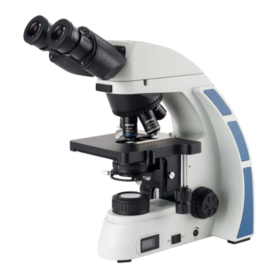
Page 5: Components
1. Components Series series biological microscope Objective Nosepiece Binocular Head Eyepiece Body Group Objective Tension Adjustment Stage Ring Koehler Illuminator Condenser Focus Arm Fine Focusing Light Adjustment Coarse Focusing Koehler Illuminator Knob Knob Knob... - Page 6 Series Eyepiece Gemel Binocular Head Body Group Objective Nosepiece Objective Stage Focus Arm Koehler Illuminator Condenser Fine Focusing Knob Koehler Illuminator Coarse Focusing Knob Color Temperature LCD Display Power Switch Knob...
- Page 7 Series series biological microscope(with LED fluorescence device) Light Gemel Binocular Adjustment Fluorescent filter Knob Head Eyepiece Adjustment Knob (Reflected) Lock screw LED Fluorescence Lock screw Illuminator Light Shield Objective Objective Nosepiece Body Group Stage Focus Koehler Illuminator Condenser Fine Focusing Knob Power Switch Coarse...
- Page 8 Series Fluorescence Gemel Binocular Eyepiece Illuminator Head Objective Power Cord Nosepiece Stage Body Group Focus Arm Tension Adjustment Ring Koehler Illuminator External Coarse Light Adjustment Fine Power Socket Focusing Knob(Transmitted) Focusing Knob Knob...
-
Page 9: Assembling
2. Assembling Series 2-1 Assembling Scheme Following is the Assembling Scheme, and the numbers denote the assembling order. ★ Before assembling, make sure there is no dust, dirt or other materials which will disturb it. Assemble carefully and do not scrap any part or touch the glass surface. -
Page 10: Assembling Steps
Series 2-2 Assembling Steps 2-2-1 Assemble Koehler Illuminator Condenser (1) Rotate the coarse focusing knob① to raise the stage to the highest position (see Fig. 4). (2) Rotate the condenser up-down knob② to lower the bracket of condenser to the suitable position. - Page 11 Series 2-2-3 Assemble the Eyepiece (1) Take down the cover of eyepiece tube①. (2) Insert the eyepiece② into the eyepiece tube, until it touches the surface (see Fig. 7). (3) When adjusting diopter with adjustable eyepiece, lock eyepiece with hexagon lock-screw ③...
-
Page 12: Operations
3. Operations Series 3-1 Set Illumination 1. Put through the power and turn on the main power switch to “ON”(turn on) on the side. 2. Adjust the light adjustment knob② until the illumination is comfortable for observation. 360 ° Rotate the light adjustment knob in clockwise to raise the voltage and brightness, and gradually enlarge the LCD display illumination brightness to 99%. -
Page 13: Place The Specimen Slide
Series 3-4 Place the Specimen Slide (1) Push the wrench① of the specimen holder backwards. (2) Place the slide② into the clip, loosen the wrench① and clamp the slide. Make sure the specimen faces up, while there is a cover glass, make sure the cover glass face up (see Fig. -
Page 14: Adjust The Interpupillary Distance
Series 3-8 Adjust the Interpupillary Distance When observe with two eyes, hold the base of the prism and rotate them around the axis until there is only one field of view. “。”① on the eyepiece base points to the scale② of interpupillary indication, which means the value of interpupillary distance (see Fig. -
Page 15: Aperture Diaphragm
Series 3-11 Aperture Diaphragm aperture diaphragm decides numerical aperture of the illumination system. Only when the N.A. of illumination system is matching with the N.A. of the objective, it can obtain better resolution and contrast, and also increase the depth of field. (2) As the contrast is usually low, rotate the diaphragm adjust ring③... -
Page 16: Use The Filter
Series 3-13 Use the Filter Filter can make the background be more suitable and increase the contrast (see Fig. 24). There are four colors of filter: blue, green, yellow and white. ★ Place the filter’s rough side downward. Fig.24 3-14 Use Button and Interface of the Digital Head 1) Press and hold for 3-5 seconds on the switch button①. -
Page 17: Assembling And Operation Of Accessories
4. Assembling and Operation of Accessories Series 4-1 Assembling and Operation of the LED Fluorescence Device 4-1-1 Assembling and Operation of the LED Fluorescence Illuminator (1) Fix the light shield ② on the LED fluorescence illuminator ③ with the screw ①. (See Fig. - Page 18 Series (8) Illumination: Rotate the adjustment knob② in clockwise, it will sound a “Dida” when the LED fluorescence lamp is turned on, and 关 increase the brightness in clockwise; Rotate the adjustment knob ② in counterclockwise to reduce the brightness of the LED fluorescence lamp, and turn it off until it sounds a “Dida”.
-
Page 19: Assembling And Using Of The Tv Device
Series (last grid is "red" and the remaining seven grids are "green"). (See Fig. 31, 32) 4-2 Assembling and using of the TV Device (1) Loosen the lock screw① of trinocular head, take out the triplet dust-cover②. (See Fig. 33) (2) Take down the dust-cover of the TV adapter③. -
Page 20: Assembling The Phase Contrast Device
Series 4-4 Assembling the Phase Contrast Device 4-4-1 Assembling and Operation of Phase Contrast Flapper (1) Keep the phase contrast flapper① face up (upward the face with word), insert it from left to right into the condenser flapper socket as the direction of the arrow pointed (see Fig. -
Page 21: Assembling And Operation Of Dark Field Flapper
Series (4) Adjust centering telescope to get a clear image of phase ring and halo in field of view (see Fig. 38). (5) Center by phase contrast adjusting lever③ until halo④ center overlaps the phase ring⑤ center (see Fig. 37 and 38). (6) Adjust phase ring and halo of other magnification phase contrast objective according to the above steps. -
Page 22: Operation Of Digital Observation Head
Series 4-7 Operation of Digital Observation Head Insert one end of USB data cable into the USB output port① on the back of observation head, and the other end into the USB interface of PC (see Fig. 41). View the microscope video by the corresponding video capture... -
Page 23: Troubleshooting
5. Troubleshooting Series As the performance of microscope can’t play fully due to unfamiliar operations, the table below can provide some solutions. Problem Cause Solution 1. Optical Part Field diaphragm is not large Enlarge the field diaphragm. enough. (1) The LED light Condenser is too low. - Page 24 (6) The eyes feel Interpupillary distance is wrong. Adjust the interpupillary distance. tired easily. right field of view doesn’t superpose Diopter adjustment is wrong. Adjust the Diopter. with the left. 2. Mechanical Part The cover glass faces down. Put the cover glass to face up. (1) Cannot get the objective focused in Use a standard cover glass with...
- Page 25 Turn on the LED fluorescence adjustment knob switch to bright The LED fluorescence enough, rotate the fluorescence adjustment knob switch is not filter block adjustment knob to turned on. “Fluorescence”, and check if the light source is on. (1) LED Check power cable...
Need help?
Do you have a question about the A12.0911 and is the answer not in the manual?
Questions and answers