
Related Manuals for OPTO-EDU A13.1005-B


Summary of Contents for OPTO-EDU A13.1005-B
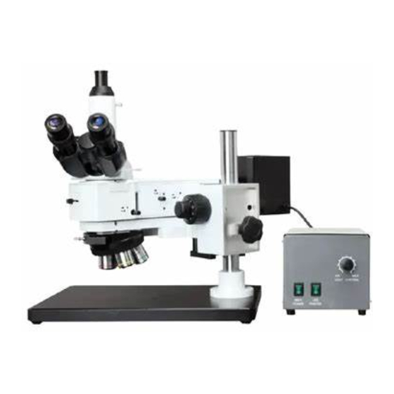
- Page 1 A13.1005 Metallurgical Microscope, Bright Field/Dark Field Instruction Manual To ensure the safety and obtain satisfactory performance, please study this instruction manual thoroughly before start to use your instrument.
-
Page 2: Table Of Contents
Contents A13.1005 „„„„„„„„„„„„„„„„„„„„„„„„ „2 User Notice „„„„„„„„„„„„„„„„„„„„„„ 1 Component Names „„„„ „„„„„„„„„„„„„„„„„„„„„ 2 Assembly 2-1Assembly diagrams„„„„„„„„„„„„„„„„„„„„„ 5 2-2Assembly steps 2-2-1 install L-plate„„„„„„„„„„„„„„„„„„„„„6 2-2-2 Install supporting component„„„„ „„„„„„„„„„6 2-2-3 Install fine-coarse movement component „„„„„„„„„6 2-2-4Install connecting plate„„„„„„„„„„„„„„„ „„7 2-2-5 Install converter and objective„„„„„„„„„„„„„„7 2-2-6 Install metallographic device„„„„„„„„„„„„„„„7 2-2-7Install viewing head„„„„„„„„„„„„„„„„„„„8 3 Adjustment and Operation... - Page 3 User A13.1005 1. Safety Symbols symbol explanation Indicates that the surface becomes hot, and should not be touched with bare hands。 Before use, carefully read the user manual .Improper use could result in personal injury to the user and/or damage to the equipment. Indicates that the main switch is ON.
- Page 4 A13.1005 3. Maintenance and Care 1. All the lenses have been adjusted properly; do not dismount them by yourself please. 2. The nosepiece and coarse and fine focusing parts are so delicate that it is forbidden to disassemble them carelessly by yourself. 3.
-
Page 5: Component Names
1. Component Names A13.1005 Power box... -
Page 6: Assembly
2.Assembly A13.1005 2-1 Assembly Diagram The following picture shows the sequence of the modules in which the number stand for the steps of assemble. Before assembling, make sure that every module is free of dusts and dirt. Do not scratch any modules or glass surfaces. -
Page 7: 2-2Assembly Steps
2-2Assembly Steps A13.1005 2-2-1 Install L-plate(pic.1) Fix the L-plate and the fine-coarse movement component together by 4 matched bolts and washers. Pic.1 2-2-2 Install supporting component (pic.2) Insert the supporting component to the corresponding holes on the L-plate and fix it on the fine-coarse movement component by 4 matched bolts and washers. -
Page 8: Install Converter And Objective„„„„„„„„„„„„„„7
A13.1005 2-2-4 Install connecting plate(pic.4) ○ Put the connecting plate on the L-plate and fix it by 4 matched bolts. Make sure the ○ ○ locating surface is adjacent with the ○ surface 2 of the L-plate 2-2-5 Install converter and objective Pic.4 (pic.5)... - Page 9 A13.1005 2-2-7 Install viewing head(pic.7) 1. Put trinocular viewing head onto the swallow-tail of the connecting-plate and ○ screw bolt 1 to fix the viewing head. ○ 2. Insert the eyepiece to the lens cone of the viewing head. Pic.7...
-
Page 10: Adjustment And Operation
3. Adjustment and Operation A13.1005 3-1Connect power source and regulate light(pic.1,pic.2) 1. Connect the air plug of halogen lamp ○ house with the aerial socket of the ○ power box, plug one head of power line to ○ socket and the other head to the power ○... - Page 11 A13.1005 3-3 Adjustment of coarse focus hand ○ wheel(pic.4) The loose condition of coarse focus hand wheel can be adjusted by turning the adjusting ○ ring The coarse focus hand wheel is in a loose state when delivered, a heavy force is needed to rotate the hand wheel.
- Page 12 A13.1005 3-6 3-gear light path switch(pic.7) ○ 1. When not using cameras, totally push in the light path switch rod and observing by eyepiece. Use the 10× objective to focus, first descend the focusing component and find the image in the 10× eyepiece, then turn the fine focusing hand wheel until clearly imaged.
- Page 13 A13.1005 3-7 Usage of color filter(pic.8,pic.9) Plug needed color filter in position1 (position 2 when use LED), make sure the filter is well settled. ○ Pic.8 Color filters Function Ground glass Adjust the brightness ○ of the light Green filter Increase the contrast when single...
-
Page 14: Components Size
4.Main Component Size A13.1005 . Size of the focusing components 2. Focusing component and L-plate... -
Page 15: Technical Specification
5.Technical specification A13.1005 1. Main technical specification Optical A13.1005-B A13.1005-BD infinity optical system systems ● Hinge type trinocular (big aperture),30° tilt,pupil distance 47-78mm Viewing head ● Hinge type trinocular,30° tilt,pupil distance 78mm 47-78mm ● Huge FOV eyepiece EW10X/25,lens cone Φ30 eyepiece ●... -
Page 16: Trouble Shooting
6.Trouble Shooting A13.1005 6.1 Optical system Problem Cause Solution The nosepiece is not located in the Adjust it into the right position The edge of the field required position of view has shadow The filament is not in center Make it in center evenly There are stains on the lens Clean it... - Page 17 A13.1005 6.3 Electrical System Problem Cause Solution No power supply Check the power cord, and connect them exactly The lamp can’t the installation of the bulb is Install the bulb correctly light wrong The bulb burned out Replace with a new bulb Use the required lamp.
Need help?
Do you have a question about the A13.1005-B and is the answer not in the manual?
Questions and answers