Table of Contents
Advertisement
Quick Links
A15.1091
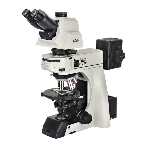
Polarizing Microscope, Semi-APO,
Transmit & Reflect Light
Instruction Manual
This manual is applicable to A15.1091 laboratory biological microscopes. In order to ensure safety,
perform optimally with the instrument, and make you fully familiar with the use of this microscope, we
recommend that you read the manual thoroughly and carefully before operating the microscope.
www.optoedu.com
1/33
sale@cnoec.com
Advertisement
Table of Contents

Related Manuals for OPTO-EDU A15.1091


Summary of Contents for OPTO-EDU A15.1091
- Page 1 Transmit & Reflect Light Instruction Manual This manual is applicable to A15.1091 laboratory biological microscopes. In order to ensure safety, perform optimally with the instrument, and make you fully familiar with the use of this microscope, we recommend that you read the manual thoroughly and carefully before operating the microscope.
-
Page 2: Table Of Contents
Contents A15.1091 Before Use ..........................4 1.Name of each part ......................... 6 1.Name of each part ........................7 1. Name of each part ........................8 2.Overview of each institution ....................9 3. Adjustment and operation ....................15 3-1 Turn on the power (Figure 1) ..................15 3-2 Adjust light intensity and switch up and down light source (Figure 2) ...... - Page 3 4-2 步骤 ..........................25 4-2-1 Installation of mechanical carrier bays(Figure 1 , 2) ........25 4-2-2 Install the polarizing platform (figure 3, 4) ............25 4-2-3Install the polarizing moving ruler (Figure 5) ............26 4-2-4 Installation converter (Figure 6) ................26 4-2-5Install metallographic device (Figure 7) ..............
-
Page 4: Before Use
Know Before Use A15.1091 Ⅰ.Safety signs The following signs are on the microscope. Find out what these symbols mean and always use the microscope in the safest way. Sign Significance Indicates that the main power switch is on. Indicates that the main power switch is off. - Page 5 A15.1091 Ⅲ.Maintenance and maintenance All lenses are tuned and do not disassemble themselves. Objective converter and coarse micro-focusing mechanism, the structure is precise, please do not easily disassemble. The instrument should be kept clean, dust removed every day, clean should pay special attention not to contaminate optics, objective lenses every other month to ask professionals to clean.
-
Page 6: Name Of Each Part
1.Name of each part A15.1091 Eyepiece Three-eye head Burgundy mirror device. Converter Object ive. Polarizing platform. Spotlight. Polarizing bay. Host. A15.1091 www.optoedu.com 6/33 sale@cnoec.com... -
Page 7: Name Of Each Part
1.Name of each part A15.1091 Eyepiece Three-eye tilted head Burgundy mirror metallographic device. device phase device Converter Objec tive. Polarizing platform. Spotlight. Polarizing bay. Host. A15.1091-TRF... -
Page 8: Name Of Each Part
1. Name of each part A15.1091 Eyepiece Three-eye tilted head Burgundy mirror device. metallographic device Converter Objective Polarizing platform Host A15.1091-RF www.optoedu.com 8/33 sale@cnoec.com... -
Page 9: Overview Of Each Institution
2.Overview of each institution A15.1091 7. Polarizer 1. Filter switch bar 8. Condenser diaphragm 2. Rough /fine-tuning lift adjusting ring handwheel 9. Adjusting screw 3. Focus the upper bit lock the 10. Platform cursor handwheel 11. Extended function plug 4. Light up and down the toggle... - Page 10 A15.1091 11 12 Observe the light path switch 8. Rough tension adjustment Analyzer handwheel Condenser fastening screw 9. Light chamber fastening screws The height of the spotlight adjusts 10. Ground screw the handwheel. 11. Light room socket Taking pictures 12. Light room plug The field diaphragm light size 13.
- Page 11 A15.1091 A15.1091-TRF 10. Adjusting screw 1. Filter switch bar 11. Platform cursor 2. Rough /fine-tuning lift handwheel 12. Extended function board fastening 3. Focus the upper bit lock the handwheel screws 4. Light up and down the toggle button 13. Extended function board 5.
- Page 12 A15.1091 9 10 A15.1091-TRF Observe the light road switch 11. Light chamber fastening screws Analyzers 12. Ground screw The analyzers slot 13. Light room socket Light gate switch button 14. Light room plug Condenser fastening screw 15. Universal wrench The height of the spotlight adjusts the 16.
- Page 13 A15.1091 A15.1091-RF Rough /fine-tuning lift handwheel Extended function board fastening Focus the upper gear bit Lock the screws handwheel Extended function board Brightness adjustment knob Labels “ECO" Infrared sensing device 10. Light / dark field switch Adjusting screw 11. Burgundy mirror turntable Polarizer 12.
- Page 14 A15.1091 A15.1091-RF Light room socket Observe the light road switch Universal Wrench analyzers 10. 16.The upper illumination aperture analyzer slot diaphragm adjusts lever Light gate switch button 11. Diaphragm adjusting screw Rough/ fine-tuning handwheel 12. The upper illumination field Rough tension adjustment...
-
Page 15: Adjustment And Operation
3. Adjustment and operation A15.1091 3-1 Turn on the power (Figure 1) Turn on the power and dial the main switch (as shown) on the back of the microscope body to the "-" (on) state. 3-2 Adjust light intensity and switch up and... -
Page 16: Specimen Placement
A15.1091 3-4 Specimen placement (figure 4) Slowly push the cover slide up into the moving ruler and gently clamp the carrier slide. Move the sample to the desired position by ① on The Rotating Figure 4. Be careful when replacing objective lenses. The ①... -
Page 17: Focusing
A15.1091 3-7 Focusing (Figure 6 -8) 1. When the camera device is not used. Push the light-way switching push lever 6 (shown in Figure 6) completely for binocular observation. With 10 × objective focus, in order to prevent specimens and... -
Page 18: Swing-Out Condenser Adjustment
A15.1091 3-10 Swing-out condenser adjustment ① ④ (Figure10 , 11) ⚫ The center of the spotlight should be concentric with the objective optical axis, the product has been adjusted at the factory, the user does not ③ have to adjust itself. -
Page 19: Use Of Color Filters
A15.1091 3-11 Use of color filters (figure 12) As shown in Figure 12, when the push rod is pushed in, it is the color filter usage state, and when the putter is pushed out, it is the filter empty state .LBD is a color filter with a color temperature filter, ND25 is a color filter with a light push rod . -
Page 20: Fuse Replacement(Figure 16)
A15.1091 3-14 Fuse replacement(Figure 16) The drawer of the fuse box is first6 opened with a universal adjustment wrench, as shown in Figure 16. As shown in Figure 17, gently top the fuse from the bottom to the top of the square hole under the fuse drawer with a universal adjustment wrench. -
Page 21: The Use Of Bertrand Lens(Figure 19)
A15.1091 3-16 The use of Bertrand lens(Figure 19) Rotating wheel ①can adjust Bertrand has mirror into or out of the light path. At the "O" position, the Burcher mirror moves out of the light path. At the "B" position, the Burcher mirror moves into the light path. -
Page 22: Use Aperture Diaphragm(Figure 23)
A15.1091 (Figure 22) Reflected light in the light field observation ④ ② The field of view light adjusts the lighting area to obtain a high contrast image. Adjust the field of view light knob of the reflector (③in Figure 20 )until the light-light image is external to the field of view to shield unnecessary light. -
Page 23: Use The Polarizer And The Analyze (Figure 24)
A15.1091 3-21 Use the polarizer and the analyze (Figure 24) ① 1. Face the screened surface of the polarizer (Figure 25)forward, insert the polarizer slot (②in Figure 24), and then move the polarizer into the light path. 2. Remove the dust cover and push the analyze (Figure ②... -
Page 24: 4.Install
4.Install A15.1091 4-1 Installation illustration. The following image shows the order in which the components are installed, and the numbers in the figure represent the installation steps. Before installation, make sure that all components are free of dust and dirt. Do not scratch any components or glass surfaces. -
Page 25: Installation Of Mechanical Carrier Bays(Figure 1 , 2
4-2 步骤 A15.1091 4-2-1 Installation of mechanical carrier bays ① (Figure 1 , 2) Rotating the coarse hand wheel causes the rack swallow tail to 1 rise to the limit screw to expose the end face as shown, and then the platform carrier is installed in accordance with the path of Figure 1 serial number ①... -
Page 26: 4-2-3Install The Polarizing Moving Ruler (Figure 5)
A15.1091 4-2-3Install the polarizing moving ruler (Figure 5) Install the polarizer moving ruler. Insert the 2 positioning pins at the bottom of the polarizing gauge into the 2 positioning holes③on the platform and tighten the tight screws with an inner hex wrench. -
Page 27: Install Bertrand Lens Set (Figure 8)
A15.1091 4-2-6 Install Bertrand lens set (Figure 8) Load the Bourbon mirror into the head of the microscope body or the gold phase device in accordance with the medium sequence number ⑥ Ⅴ ⑥ in Figure 8, transfer to the appropriate position and tighten the screw (At V. -
Page 28: 4-2-8Installation Eyepiece (Figure 10)
A15.1091 ⑨ 4-2-8Installation eyepiece (Figure 10) Insert the eyepiece in the observation head eyepiece barrel in the path mid-sequence number in Figure 10 until the end. Figure 10 4-2-9 Install objective lens (figure 11) 1. Adjust the coarse-tuned handwheel until the mechanical carrier bench support unit drops to its low limit. -
Page 29: 4-2-11Replace The Camera Interface (Optional) (Figure 13
A15.1091 4-2-11Replace the camera interface (optional) (Figure 13 Ⅹ and 14) First, as shown in Figure 13, the screw at the serial number X is spun outwards in the direction of the arrow so that it no longer tops the camera interface, and then the camera interface is rotated out. -
Page 30: Technical Specifications
Figure 16 5. Technical specifications A15.1091 Ⅰ. The main technical specifications A15.1 A15. A15.10 Optical system. NIS60 Infinite Far Optical System. 091TR 1091 Hinged tri-eye head, tilted at 30°, with a ● pitch of 47-78mm. Observation head. Variable angle tridonoms,0 to 35degrees ●... -
Page 31: 6.Troubleshooting Guide
6.Troubleshooting guide NP910 6.1 Optical parts Question The cause of Solution Converter is not in position Go to the position (turn the (objective is not in the center of animal mirror to get it right into The edges are dark or the light path) the light path) field of view is uneven. - Page 32 A15.1091 The spotlight is not tilted at Refit the spotlight and carefully the center of the field of view adjust it with the focus mirror or in the spotlight. tuning center screw. One side of the image is dimmed. The converter is not located.
- Page 33 A15.1091 6.3 Electrical section. Symptoms Reason. Countermeasures. Check the connection of the No power. wires. Switch The bulb does not The bulb is not plugged in. Insert correctly . light when switch is on. The light bulb is broken. Replace.
Need help?
Do you have a question about the A15.1091 and is the answer not in the manual?
Questions and answers