Table of Contents
Advertisement
Quick Links
Advertisement
Table of Contents

Subscribe to Our Youtube Channel
Related Manuals for Rimage Allegro 20


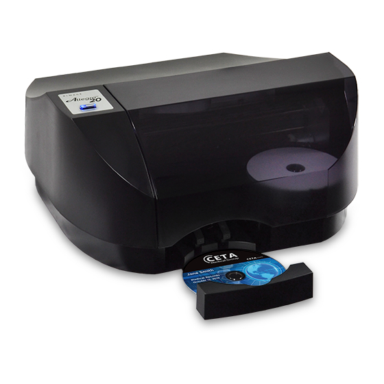
Summary of Contents for Rimage Allegro 20
- Page 1 Allegro 20 Disc Publishing System Service Manual...
-
Page 2: Table Of Contents
Section 23 - Print Tray ........................41 Section 24 - Carrier Frame ......................42 Section 25 - Troubleshooting ......................44 Rimage® is a registered trademark of Rimage Corporation. Allegro™ is a trademark of Rimage Corporation. © 2017, Rimage Corporation A20SVC - 0917... -
Page 3: Section 1 - Cover
Allegro 20 Disc Publishing System Service Manual Section 1 - Cover Turn unit over. Remove 2 screws securing back of cover. Remove 2 screws securing front of cover. Unplug control panel cable from mainboard while lifting cover off of unit. -
Page 4: Section 2 - Control Panel
Allegro 20 Disc Publishing System Service Manual Section 2 - Control Panel Unplug cable. Remove 2 screws securing control panel. Remove push spacers and snap into new control panel. Secure to cover and connect cable. Press button on top of cover and be sure it clicks properly. -
Page 5: Section 3 - Usb3 Hub
Allegro 20 Disc Publishing System Service Manual Section 3 - USB3 Hub Unplug eSata cable. Remove 3 screws securing board and ground strap. Remove spacer and snap into new USB3 hub. Replace hub, making sure pins properly plug into connectors on mainboard. Be sure to replace ground strap. Longer screw goes through spacer. -
Page 6: Section 4 - Mainboard
Allegro 20 Disc Publishing System Service Manual Section 4 - Mainboard Remove USB3 hub (see USB3 Hub). Unplug all 8 or 9 cables from mainboard. Remove 2 screws securing mainboard. Lift mainboard while pulling to the left to remove from unit. -
Page 7: Section 5 - Encoder Wheel Sensor
Allegro 20 Disc Publishing System Service Manual Remove 2 screws securing static brush to mainboard. Attach static brush to topside of new mainboard. Section 5 - Encoder Wheel Sensor Unplug encoder wheel sensor from mainboard. Remove 2 screws securing sensor to bracket. -
Page 8: Section 6 - Drive Fan
Allegro 20 Disc Publishing System Service Manual Secure new encoder wheel sensor and plug into mainboard. Be sure encoder wheel is captured in center of sensor. Section 6 - Drive Fan Cut tie wrap. Unplug fan cable from mainboard. Remove ground strap from corner of USB3 hub. - Page 9 Allegro 20 Disc Publishing System Service Manual Flip unit over. Remove 2 screws securing fan bracket. Lift bracket up, pulling fan cable out though opening in unit. Remove 2 screws securing fan to bracket. Attach new fan and place bracket back into unit. Plug fan cable into mainboard.
-
Page 10: Section 7 - Drive
Allegro 20 Disc Publishing System Service Manual Section 7 - Drive Remove 4 screws and washers securing drive to underside of unit (upper left screw can be accessed through notch in mainboard). Flip unit over. Remove 2 screws securing fan bracket. Lift bracket out of unit. - Page 11 Allegro 20 Disc Publishing System Service Manual Unplug both cables from back of drive. Push disc tray out. Lift drive up out of unit. Remove 4 screws securing left and right brackets to drive. Secure brackets to bottom set of holes on new drive.
-
Page 12: Section 8 - Exhaust Fan
Allegro 20 Disc Publishing System Service Manual Place drive into unit and plug both cables into back. Replace fan bracket. Replace 4 screws and washers from top of unit, leaving screws slightly loose. Section 8 - Exhaust Fan Unplug exhaust fan cable from mainboard. - Page 13 Allegro 20 Disc Publishing System Service Manual Flip unit over. Remove 2 screws securing fan cover plate. Remove 2 screws securing fan. Replace fan and fan cover plate. Plug fan into mainboard. Rimage Corporation Page 13...
-
Page 14: Section 9 - Maintenance Felt
Allegro 20 Disc Publishing System Service Manual Section 9 - Maintenance Felt Flip unit over. Remove 2 screws securing fan cover plate. Remove 3 pieces of maintenance felt. Wipe up any excess ink before installing new felt. Place longer felt pad on bottom and stack smaller ones on top. Replace fan cover plate. -
Page 15: Section 10 - Encoder Wheel
Allegro 20 Disc Publishing System Service Manual Section 10 - Encoder Wheel 10.1 Peel off bent or damaged encoder wheel. Clean end of gear with alcohol before adhering new encoder wheel. Section 11 - Feed Drive Motor 11.1 Use T8 driver to remove 2 screws securing motor. Carefully fold up edge of encoder wheel to access bottom screw. -
Page 16: Section 12 - Picker
Allegro 20 Disc Publishing System Service Manual 11.2 Unplug motor from mainboard. When replacing motor be sure to route cable through small notch on frame. Notch Section 12 - Picker 12.1 Unplug picker flex cable from mainboard. Rimage Corporation Page 16... - Page 17 Allegro 20 Disc Publishing System Service Manual 12.2 Peel flex cable away from double sided tape and pull out through carrier frame. 12.3 Press down on encoder strip slightly to pull it out of sensor slot and route behind carrier.
- Page 18 Allegro 20 Disc Publishing System Service Manual 12.4 Remove screws from both ends of carrier shaft. Using 2 drivers to remove both screws at the same time helps prevent shaft from spinning. 12.5 Pull out on left end of carrier shaft to pop it out of carrier frame. Slide picker off of shaft and remove from unit.
-
Page 19: Section 13 - Picker Arm
Allegro 20 Disc Publishing System Service Manual 12.6 When replacing picker, be sure picker and carrier are properly captured on top edge of carrier frame. Press carrier shaft back into frame, tightening both screws at the same time to prevent it from spinning. - Page 20 Allegro 20 Disc Publishing System Service Manual 13.2 Remove retaining ring from top of shaft. Push up on bottom of shaft to remove it from assembly. Ring 13.3 Unplug small flex cable from picker arm. Pull up on end of picker arm to lift it up off of nut.
-
Page 21: Section 14 - Lead Screw
Allegro 20 Disc Publishing System Service Manual 13.4 When attaching picker arm back onto picker, be sure edge of disc picker frame is captured by slot on picker arm (left pic). Replace shaft and retaining ring. Plug flex cable back into picker arm. -
Page 22: Section 15 - Picker Interface Board & Flex Cable
Allegro 20 Disc Publishing System Service Manual 14.2 When replacing motor, place tip of screw and bearing into hole on frame first. Then pry up on top frame while pressing motor in. Be sure corner of motor is captured on tab on back side of frame. - Page 23 Allegro 20 Disc Publishing System Service Manual 15.2 After replacing interface board and/or flex cables, route cables through slots on board, as shown. 15.3 When replacing board, route large flex cable through slots on frame as shown. Rimage Corporation Page 23...
-
Page 24: Section 16 - Solenoid
Allegro 20 Disc Publishing System Service Manual Section 16 - Solenoid 16.1 Remove picker assembly (see Picker). Use a narrow flathead screwdriver to pry cover off of tabs on disc picker arm. 16.2 Remove spring. Rimage Corporation Page 24... - Page 25 Allegro 20 Disc Publishing System Service Manual 16.3 Unplug solenoid cable from board. Remove 2 screws securing solenoid in picker arm. 16.4 Pull solenoid cable out through opening in picker. Lift solenoid out. Rimage Corporation Page 25...
-
Page 26: Section 17 - Picker Arm Board & Sensor Flag Bracket
Allegro 20 Disc Publishing System Service Manual 16.5 When installing new solenoid route both wires of cable around to right side and through small slot. Section 17 - Picker Arm Board & Sensor Flag Bracket 17.1 Remove picker assembly (see Picker). Unplug solenoid cable from picker arm board. - Page 27 Allegro 20 Disc Publishing System Service Manual 17.2 Use a flathead screwdriver to slightly pry out inside tab while pulling up and out on board. While continuing to pull on board, slightly pry out other tab to release board. Replace picker arm board and/or sensor flag bracket.
-
Page 28: Section 18 - Carrier
Allegro 20 Disc Publishing System Service Manual Section 18 - Carrier 18.1 Unplug both carrier flex cables from mainboard. Press tab on flex holder to remove from carrier frame. Pull flex cables out through frame. Press 18.2 Remove screw from carrier belt tensioner. Press in on tensioner to slacken and pull belt off. - Page 29 Allegro 20 Disc Publishing System Service Manual 18.3 Press down on encoder strip slightly to pull it out of sensor slot and route behind carrier. Through Slot Behind Slot 18.4 Remove screws from both ends of carrier shaft. Using 2 drivers to remove both screws at the same time helps prevent shaft from spinning.
- Page 30 Allegro 20 Disc Publishing System Service Manual 18.5 Pull out on left end of carrier shaft to pop it out of carrier frame. Slide carrier off of shaft and remove from unit. 18.6 When replacing carrier, be sure picker and carrier are properly captured on top edge of carrier frame.
-
Page 31: Section 19 - Alignment Sensor
Allegro 20 Disc Publishing System Service Manual Section 19 - Alignment Sensor 19.1 Remove carrier from unit (see Carrier). Remove 2 screws indicated. 19.2 Press up on corner of lower capture lever just enough to access screw indicated (do not completely remove lever). - Page 32 Allegro 20 Disc Publishing System Service Manual 19.3 Slightly pry both frames apart just enough to pull alignment sensor wires out from tab. 19.4 Remove screw securing quad sensor carrier bracket. Rimage Corporation Page 32...
- Page 33 Allegro 20 Disc Publishing System Service Manual 19.5 Unplug alignment sensor from carrier flex pc. Connect new alignment sensor. 19.6 When reassembling carrier be sure to snap end of quad sensor carrier bracket onto tab on frame before replacing screw. Be sure to route alignment sensor wires behind tab before replacing 2 screws and retightening 1 screw.
-
Page 34: Section 20 - Carrier Flex Pc
Allegro 20 Disc Publishing System Service Manual Section 20 - Carrier Flex PC 20.1 Remove carrier from unit (see Carrier). Remove 3 screws indicated. 20.2 Press up on lower capture lever to detach from unit. Lift lever off of unit, pulling belt through opening. - Page 35 Allegro 20 Disc Publishing System Service Manual 20.3 Remove screw securing quad sensor carrier bracket. Remove 2 screws (T8 driver). As both frames separate, lift carrier flex pc out of assembly. 20.4 Use a small flathead screwdriver to pry and pop sensor out of quad sensor carrier bracket. Press sensor from new carrier flex pc into bracket until it snaps into place.
- Page 36 Allegro 20 Disc Publishing System Service Manual 20.5 Fold and crease carrier flex pc in locations shown. Place holes onto tiny tabs on bracket. Plug alignment sensor in. Place new carrier flex pc into frame. Fold Tabs Fold 20.6 When reassembling carrier be sure to snap end of quad sensor carrier bracket onto tab on frame before replacing screw.
- Page 37 Allegro 20 Disc Publishing System Service Manual 20.7 Gripping spring with tweezers, slide it in between lower capture lever and carrier base. Hold spring in center and snap lower capture lever back into place while removing tweezers. Spring should remain captured between parts. Be sure spring is centered and sitting straight up and down.
-
Page 38: Section 21 - Encoder Strip
Allegro 20 Disc Publishing System Service Manual Section 21 - Encoder Strip 21.1 Unhook encoder strip spring from left side of carrier frame. Pull left end of encoder strip off of tab then unhook right end. When replacing encoder strip hook right end before attaching spring. -
Page 39: Section 22 - Carrier Drive Motor
Allegro 20 Disc Publishing System Service Manual Section 22 - Carrier Drive Motor 22.1 Unplug carrier drive motor from mainboard. 22.2 Remove 2 screws securing both ends of carrier shaft. Remove screw securing carrier belt tensioner (belt can be left in place). - Page 40 Allegro 20 Disc Publishing System Service Manual 22.3 Pop left end of carrier shaft out of place and lift slightly up slightly to gain access to bottom screw. Remove 2 screws (T8 driver) securing carrier drive motor. Lift 22.4 Install new motor (be sure to include spacer). Pop left end of carrier shaft back into place and replace both screws, tightening at the same time to prevent it from spinning.
-
Page 41: Section 23 - Print Tray
Allegro 20 Disc Publishing System Service Manual Section 23 - Print Tray 23.1 Remove mainboard (see Mainboard). Unhook belt from belt clamp bracket. Remove screw. 23.2 Pull tray completely back to align belt clamp bracket with notch in base. Lift end of bracket to snap up off of base. -
Page 42: Section 24 - Carrier Frame
Allegro 20 Disc Publishing System Service Manual 23.3 Lift up back end of tray and pull out to remove from unit. Section 24 - Carrier Frame 24.1 Remove print tray (see Print Tray). Loosen screw securing belt tensioner. Pull belt off of belt tensioner. - Page 43 Allegro 20 Disc Publishing System Service Manual 24.2 Remove 3 screws securing front of carrier frame. Remove carrier frame from base by lifting and pulling forward. 24.3 When replacing carrier frame, press tabs on back of each end into slots on base.
-
Page 44: Section 25 - Troubleshooting
Allegro 20 Disc Publishing System Service Manual Section 25 - Troubleshooting Symptoms During Initialization Possible Solution No carrier or print tray (solenoid clicks and Carrier drive motor (see Carrier Drive Motor) picker moves twice) Blinking control panel No print tray (carrier moves, solenoid clicks... - Page 45 Allegro 20 Disc Publishing System Service Manual Symptoms During Operation Possible Solution Solenoid (see Solenoid) Picker drops down onto discs in bins multiple times but does not grab disc. Picker grabs disc but does not drop onto print Picker arm board or sensor flag bracket (see tray or drive.
Need help?
Do you have a question about the Allegro 20 and is the answer not in the manual?
Questions and answers