
Related Manuals for EWM L1.04 - RC XQ Expert 2.0


Summary of Contents for EWM L1.04 - RC XQ Expert 2.0
- Page 1 Operating instructions Control L1.04 - RC XQ Expert 2.0 Rob L1.05 - RC XQ Expert 2.0 Rob 099-00L104-EW501 Observe additional system documents! 17.01.2022...
- Page 2 +49 2680 181-0. A list of authorised sales partners can be found at www.ewm-group.com/en/specialist-dealers. Liability relating to the operation of this equipment is restricted solely to the function of the equipment. No other form of liability, regardless of type, shall be accepted.
-
Page 3: Table Of Contents
Contents Notes on using these operating instructions Contents 1 Contents ............................3 2 For your safety ..........................5 Notes on using these operating instructions ................5 Explanation of icons ....................... 6 Safety instructions ........................7 Transport and installation ....................10 3 Intended use .......................... - Page 4 Contents Notes on using these operating instructions 5.5.2 Load JOB(s) ......................32 5.5.3 Save configuration ....................32 5.5.3.1 System....................32 5.5.3.2 Xnet machine ..................32 5.5.4 Load configuration ....................32 5.5.4.1 System....................32 5.5.4.2 Xnet machine ..................32 5.5.5 Load languages and texts..................32 5.5.6 Record on USB drive ....................
-
Page 5: For Your Safety
For your safety Notes on using these operating instructions For your safety Notes on using these operating instructions DANGER Working or operating procedures which must be closely observed to prevent imminent serious and even fatal injuries. • Safety notes include the "DANGER" keyword in the heading with a general warning symbol. •... -
Page 6: Explanation Of Icons
For your safety Explanation of icons Explanation of icons Symbol Description Symbol Description Indicates technical aspects which the u- Activate and release / Tap / Tip ser must observe. Switch off machine Release Switch on machine Press and hold Switch Incorrect / Invalid Turn Correct / Valid... -
Page 7: Safety Instructions
For your safety Safety instructions Safety instructions WARNING Risk of accidents due to non-compliance with the safety instructions! Non-compliance with the safety instructions can be fatal! • Carefully read the safety instructions in this manual! • Observe the accident prevention regulations and any regional regulations! •... - Page 8 For your safety Safety instructions WARNING Risk of injury due to improper clothing! During arc welding, radiation, heat and voltage are sources of risk that cannot be avoided. The user has to be equipped with the complete personal protective equipment at all times.
- Page 9 For your safety Safety instructions CAUTION Smoke and gases! Smoke and gases can lead to breathing difficulties and poisoning. In addition, solvent vapour (chlorinated hydrocarbon) may be converted into poisonous phosgene due to the ultraviolet radiation of the arc! • Ensure that there is sufficient fresh air! •...
-
Page 10: Transport And Installation
For your safety Transport and installation CAUTION Obligations of the operator! The respective national directives and laws must be complied with when operating the machine! • Implementation of national legislation relating to framework directive 89/391/EEC on the int- roduction of measures to encourage improvements in the safety and health of workers at work and associated individual guidelines. - Page 11 For your safety Transport and installation CAUTION Risk of accidents due to supply lines! During transport, attached supply lines (mains leads, control cables, etc.) can cause risks, e.g. by causing connected machines to tip over and injure persons! • Disconnect all supply lines before transport! Risk of tipping! There is a risk of the machine tipping over and injuring persons or being damaged itself during movement and set up.
-
Page 12: Intended Use
Intended use Use and operation solely with the following machines Intended use WARNING Hazards due to improper usage! The machine has been constructed to the state of the art and any regulations and stand- ards applicable for use in industry and trade. It may only be used for the welding proce- dures indicated at the rating plate. -
Page 13: Part Of The Complete Documentation
Intended use Documents which also apply 3.4.1 Part of the complete documentation This document is part of the complete documentation and valid only in combination with all other parts of these instructions! Read and observe the operating instructions for all system components, especially the safety instructions! The illustration shows a general example of a welding system. -
Page 14: Quick Overview
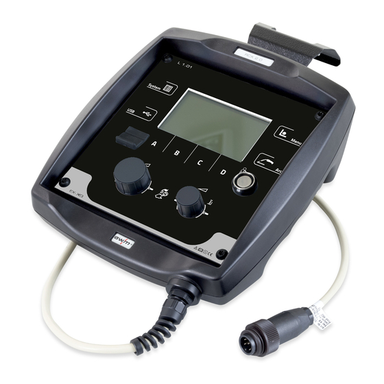
Quick overview Machine control – Operating elements Quick overview Machine control – Operating elements Figure 4-1 Item Symbol Description Push-button for system settings Display for system and configuration of system settings > see 5.4.4 chapter. Machine display Machine display showing all machine functions, menus and parameters with their va- lues >... -
Page 15: Screen Icons
Quick overview Screen icons Item Symbol Description Arc push-button • Initial state of main screen: Switch between main screen types 1 and 2. • Initial state of any sub-menu: Display switches back to the main screen. • Press and hold: After 3 s the machine changes to the lock mode. To unlock, press and hold again for 3 s. -
Page 16: Machine Display
Quick overview Machine display Symbol Description Xbutton version number not recognised Cancel operation Confirm operation Wire diameter (welding consumable) Menu navigation; one menu back Menu navigation; expanding the content of the display Save data to USB medium Load data from USB medium USB data recording Screen type 3/4, switching buttons Pulse arc welding... -
Page 17: Main Screen
Quick overview Machine display 4.3.2 Main screen The main screen shows all the information relevant for the welding process before, while and after it is carried out. In addition, it shows status information on the machine state. The assignment of the context- dependent push-buttons is also shown on the main screen. -
Page 18: Initial Screen
Quick overview Machine display Figure 4-4 You can select the required variant (type of main screen) in the Machine configuration (system) menu > see 4.3.3 chapter. You can toggle between main screen types 1 and 2 directly on the main screen as well (buttons at the top left or use the push-button Arc). -
Page 19: Change System Language
Quick overview Machine display 4.3.4.1 Change system language During the start process the user can select or change the system language at the machine control. • Switch the machine off and on again. • Press the context-dependent push-button [D] during the start phase (the word WELDING 4.0 is dis- played). -
Page 20: Operating The Machine Control
Operating the machine control Welding power setting Operating the machine control In general the control is operated with the central control button below the machine display. Select the required menu item by turning (navigate) and pressing (confirm) the central control button. In addition, the context-dependent push-buttons below the machine display can be used for confirmation. -
Page 21: Lock Function
Operating the machine control Context-dependent push-buttons 5.3.2 Lock function The lock function protects against accidental adjustment of the device settings. The user can switch the lock function on or off by pressing the button for a long time from each machine control or accessory component with the symbol 099-00L104-EW501 17.01.2022... -
Page 22: Machine Configuration (System)
Operating the machine control Machine configuration (system) Machine configuration (system) In the System menu the user can set the basic machine configuration. Enter the menu: Figure 5-1 5.4.1 Power-saving mode (Standby) You can activate the power-saving mode by setting a parameter in the configuration menu (time-control- led power-saving mode). -
Page 23: Access Permission (Xbutton)
Operating the machine control Machine configuration (system) 5.4.2 Access permission (Xbutton) The welding system offers two options to prevent unauthorised access to welding parameters or uninten- tional reconfiguration. 1 Key switch (available depending on machine version). With the key switch in position 1 all functions and parameters can be configured without any restriction. -
Page 24: Status Information
Operating the machine control Machine configuration (system) 5.4.3 Status information This menu provides the user with information on current system interferences and warnings.. 5.4.3.1 Errors and warnings Figure 5-3 Item Symbol Description Error number > see 8.2 chapter Error icons ------- Warning (prior to interference) ------- Interference (welding process will be stopped) ------- Specific (e.g. -
Page 25: Running Time
Operating the machine control Machine configuration (system) 5.4.3.2 Running time Menu item/parameter Value Comment Duty cycle can be reset: 0:00 h Values can be reset by pressing or turning the main control button Arc time can be reset: 0:00 h Overall duty cycle: 0:00 h Overall arc time:... -
Page 26: System Settings
Operating the machine control Machine configuration (system) 5.4.4 System settings In this area the user can configure advanced system settings. 5.4.4.1 Date Menu item/parameter Value Comment Year: 2014 Month: Day: Date format: DD.MM.YYYY YYYY.MM.DD 5.4.4.2 Time Menu item/parameter Value Comment Hour: 0–24 Minute:... -
Page 27: Operating Panel Settings
Operating the machine control Machine configuration (system) 5.4.5 Operating panel settings Menu item / parameter Value Comment Type of main screen Automatic selection of welding power Off–30 s Display brightness: 0-100 % Display contrast: 0-100 % Display negative: Non-latched selectable Special non-latched selectable Spot welding selectable Special latched selectable... -
Page 28: Aligning The Cable Resistance
Operating the machine control Machine configuration (system) 5.4.6 Aligning the cable resistance The resistance value of cables can either be set directly or it can be aligned using the power source. The factory setting of the power sources is 8 mΩ. This value correponds to a 5 m earth cable, a 1.5 m inter- mediate hose package and a 3 m water-cooled welding torch. - Page 29 Operating the machine control Machine configuration (system) 50mm DE - Abgleich Leitungswiderstand EN - Cable resistance alignment FR - Alignement résistance ligne IT - Compensazione resistenza circuito ES - Compensación de la resistencia del cable NL - Compensatie leidingsweerstand SE - Kalibrering av ledningsmotståndet PL - Porównanie rezystancji przewodu RU - Компенсация...
-
Page 30: Xnet Machine
The message can be reset and a new QR code may be requested from the network. 5.4.7.2 Component identification Bar codes predefined in ewm Xnet are recorded with a manual scanner. Component data are retrieved and displayed in the control. Figure 5-6... -
Page 31: Errors And Warnings
Operating the machine control Offline data transfer (USB) 5.4.7.4 Errors and warnings A list of all ewm Xnet-specific errors and warnings are displayed with their ID number and description. 5.4.7.5 Status information Figure 5-8 5.4.7.6 Network Figure 5-9 5.4.7.7 Clear system memory Resets the internal system memory used for saving welding and log data and deletes all data. -
Page 32: Save Job(S)
Operating the machine control Offline data transfer (USB) Using the USB interface, data can be transferred between the machine control and a USB storage me- dium. Figure 5-10 5.5.1 Save JOB(s) Saving a single (JOB) or a range of welding tasks (JOB)s) (from–to) from the welding machine to the sto- rage media (USB). -
Page 33: Record On Usb Drive
Operating the machine control Welding task administration (Menu) 5.5.6 Record on USB drive You can record welding data on a storage medium and read or analyse them using the Xnet quality ma- nagement software when required. For machine variants with network capability (LG/WLG) only! 5.5.6.1 Register USB drive To identify and allocate the welding data between power source and storage medium the storage medium... -
Page 34: Job Selection (Material/Wire/Gas)
Operating the machine control Welding task administration (Menu) 5.6.1 JOB selection (material/wire/gas) The welding task (JOB) can be set in two ways: a) Enter the relevant JOB number. Each welding task has a unique JOB number (for predefined JOBs > see 9.2 chapter , see the JOB list in the annex or the sticker on the machine). b) Enter the basic welding parameters: welding procedure, material type, wire diameter and shielding gas type. -
Page 35: Mig/Mag Welding
Operating the machine control Welding task administration (Menu) 5.6.3.1 MIG/MAG welding In every JOB, separate settings can be made for the ignition program, reduced main program and end program as to whether or not to alternate with the pulse process. These properties are stored on the welding machine with the JOB. -
Page 36: Advanced Settings
Operating the machine control Setup mode 5.6.3.2 Advanced settings Menu item / parameter Value Comment Process switching Start program pulsing End program pulsing Wire retraction ignition Lift arc (PP) Lift arc End pulse duration 0.0–20 ms U correction limit 0.0-9.9V Applies with correction operation enabled Wire correction limit 0–30%... -
Page 37: Wpqr Welding Data Assistant
Operating the machine control Setup mode Item Symbol Description Push-button, gas test/purge hose package • ----------- Gas test: Shielding gas (symbol flashes slowly) will flow for approximately 20 seconds after pressing the push-button once. Press the button again to cancel the pro- cess early. - Page 38 Operating the machine control Setup mode Item Symbol Description Advanced settings Display and setting of advanced process parameters WPQR welding data assistant Menu item / parameter Value Comment Automatic The welding monitoring window opens auto- matically from the main screen after a welding start.
-
Page 39: Process Parameters
Operating the machine control Setup mode 5.7.3 Process parameters 5.7.3.1 Ignition parameters Menu item/parameter Value Comment I-ign: 1–1000 A WF-ign: 0.0–100.0% 0.0- WF-ign 1: 20.0 m/min. U-ign: 0.0–38.2 V T-ign: 0.1–20.0 ms I-sense: 0–500 A WF-sense: 0.0– 20.0 m/min. 5.7.3.2 Wire retraction ignition Menu item/parameter Value... -
Page 40: Job Display Setting
Operating the machine control Online data transfer (network) 5.7.4 JOB display setting Menu item/parameter Value Comment Text for material: Standard Alternative Text for gas: Standard Alternative Absolute value set point: Start current, secondary current and end cur- rent are set and displayed as absolute values. Start current, secondary current and end cur- rent are defined and displayed as a percen- tage of program A (ex works) -
Page 41: Welding Procedure
Welding procedure MIG/MAG welding Welding procedure The welding task is selected in the JOB selection menu (material/wire/gas) > see 5.6.1 chapter. The basic settings of the relevant welding procedure, such as operating mode or arc length correction, can be selected on the main screen on the process parameter panel > see 4.3.2 chapter. The program sequence settings are set in the program sequence menu >... - Page 42 Welding procedure MIG/MAG welding Non-latched mode Figure 6-1 Step 1 • Robot issues the start signal to the power source. • Shielding gas is expelled (gas pre-flows). • Wire feed motor runs at “creep speed”. • Arc ignites after the wire electrode makes contact with the workpiece; welding current flows. •...
- Page 43 Welding procedure MIG/MAG welding Non-latched operation with superpulse For machine versions with pulsed arc welding procedures only. Figure 6-2 Step 1 • Robot issues the start signal to the power source. • Shielding gas is expelled (gas pre-flows). • Wire feed motor runs at “creep speed”. •...
- Page 44 Welding procedure MIG/MAG welding Special, non-latched Figure 6-3 Step 1 • Robot issues the start signal to the power source. • Shielding gas is expelled (gas pre-flows) • Wire feed motor runs at “creep speed”. • Arc ignites after the wire electrode makes contact with the workpiece, welding current is flowing (start program P for the time t START...
- Page 45 Welding procedure MIG/MAG welding Special, non-latched with superpulse For machine versions with pulsed arc welding procedures only. Figure 6-4 Step 1 • Robot issues the start signal to the power source. • Shielding gas is expelled (gas pre-flows) • Wire feed motor runs at “creep speed”. •...
-
Page 46: Coldarc / Coldarc Puls
Welding procedure MIG/MAG welding 6.1.2 coldArc / coldArc puls Heat-reduced, low-spatter short arc for high dimensional stability welding and brazing of thin metal sheets with excellent gap-bridging. Figure 6-5 After selecting the coldArc process > see 5.6 chapter you benefit from: •... -
Page 47: Rootarc/Rootarc Puls
(molten metal) decreases and the penetration reduces. Figure 6-8 With the EWM wiredArc arc with wire control, the welding current (AMP) changes with the change of the stick-out only slightly. The compensation of the welding current takes place with an active control of wire feed speed (DG). -
Page 48: Acarc Puls Xq
Welding procedure MIG/MAG welding 6.1.6 acArc puls XQ The alternating current welding process acArc puls XQ makes MIG aluminium welding even easier in ma- nual and automated modes. Clean weld seams with no traces of powder on the thinnest metal sheets, even with AlMg alloys, are possible with acArc puls XQ. - Page 49 Welding procedure MIG/MAG welding The basic requirement for optimum welding results is the application-specific equipment of the wire feed system. For the acArc puls XQ welding process, the entire wire feed system of the Titan XQ AC series is factory-equipped with components for aluminium welding consumables! Recommended system components: •...
-
Page 50: Maintenance, Care And Disposal
Maintenance, care and disposal General Maintenance, care and disposal General DANGER Risk of injury due to electrical voltage after switching off! Working on an open machine can lead to fatal injuries! Capacitors are loaded with electrical voltage during operation. Voltage remains present for up to four minutes after the mains plug is removed. -
Page 51: Disposing Of Equipment
Information on returning used equipment or collections can be obtained from the respective municipal administration office. Devices can also be returned to EWM sales partners across Europe. Further information on the topic of the disposal of electrical and electronic equipment can be found on our website at: https://www.ewm-group.com/de/nachhaltigkeit.html. -
Page 52: Rectifying Faults
Rectifying faults Display machine control software version Rectifying faults All products are subject to rigorous production checks and final checks. If, despite this, something fails to work at any time, please check the product using the following flowchart. If none of the fault rectification procedures described leads to the correct functioning of the product, please inform your authorised dea- ler. - Page 53 Rectifying faults Error messages Error (category) Possible cause Remedy Low coolant level low flow rate Fill coolant. Check coolant flow - remove kinks in hose package. Adjust flow threshold. [1] [3] Clean water block. Pump does not turn Turn the pump shaft. Air in the coolant circuit Vent coolant circuit.
- Page 54 Rectifying faults Error messages Error (category) Possible cause Remedy 33 Error UIST Voltage recording faulty Eliminate short circuit in welding cir- cuit. remove external sensor voltage. Request service. 34 Electronics error A/D-channel error Switch the machine off and on again. Request service.
-
Page 55: Warnings
Rectifying faults Warnings Error (category) Possible cause Remedy 56 Mains phase failure One phase of the mains voltage Check mains connection, mains plug has failed. and mains fuses. Slave tacho error Wire feeder fault (slave drive). Check connectors, cables, connec- tions. - Page 56 Rectifying faults Warnings Warning Possible cause / remedy 8 Welding circuit The inductance of the welding circuit is too high for the selected welding task. 9 WF configuration Check WF configuration. 10 Partial inverter One of several partial inverters is not supplying welding current. 11 Excess temperature of the coo- Check temperature and switching thresholds.
-
Page 57: Resetting Jobs (Welding Tasks) To The Factory Settings
Rectifying faults Resetting JOBs (welding tasks) to the factory settings Warning Possible cause / remedy 38 Incomplete component informa- Check XNET component management. tion 39 Mains half-wave failure Check supply voltage. 40 Weak power grid Check supply voltage. 41 Cooling unit not recognised Check the cooling unit connection. -
Page 58: Appendix
Appendix Parameter overview – setting ranges Appendix Parameter overview – setting ranges Parameter Setting range Comment MIG/MAG Gas pre-flow time Gas nominal value l/min GFE option Start program P START WF relative Duration 0,00 - 20,0 U correction -9,9 Slope time 0,00 20,0 Main program P... -
Page 59: Job-List
Appendix JOB-List JOB-List Diameter JOB no. Processes Material [mm] GMAW standard G3Si1 / G4Si1 100% CO2 GMAW standard G3Si1 / G4Si1 100% CO2 GMAW standard G3Si1 / G4Si1 100% CO2 GMAW standard G3Si1 / G4Si1 100% CO2 GMAW standard G3Si1 / G4Si1 100% CO2 Standard GMAW / pulse G3Si1 / G4Si1... - Page 60 Appendix JOB-List JOB no. Processes Material Diameter [mm] coldArc / coldArc puls CrNi 19 9 / 1.4316 Ar-97.5 / CO2-2.5 (M12) coldArc / coldArc puls CrNi 19 9 / 1.4316 Ar-97.5 / CO2-2.5 (M12) coldArc / coldArc puls CrNi 19 9 / 1.4316 Ar-97.5 / CO2-2.5 (M12) coldArc / coldArc puls AlMg4.5Mn...
- Page 61 Appendix JOB-List JOB no. Processes Material Diameter [mm] Standard GMAW / pulse CuAl Ar-100 (I1) Standard GMAW / pulse CuAl Ar-100 (I1) Standard GMAW / pulse CuAl Ar-100 (I1) Standard GMAW / pulse CuAl Ar-100 (I1) Brazing CuSi Ar-97.5 / CO2-2.5 (M12) Brazing CuSi Ar-97.5 / CO2-2.5 (M12)
- Page 62 Appendix JOB-List JOB no. Processes Material Diameter [mm] Block 2/ JOB4 Block 2/ JOB5 Block 2/ JOB6 Block 2/ JOB7 Block 2/ JOB8 Block 2/ JOB9 Block 2/ JOB10 Block 3/ JOB1 Block 3/ JOB2 Block 3/ JOB3 Block 3/ JOB4 Block 3/ JOB5 Block 3/ JOB6 Block 3/ JOB7...
- Page 63 Appendix JOB-List JOB no. Processes Material Diameter [mm] Flux cored wire rutile FCW CrNi Rutile CO2-100 (C1) Standard GMAW / pulse AlMg3 Ar-100 (I1) Standard GMAW / pulse AlMg3 Ar-100 (I1) Standard GMAW / pulse AlMg3 Ar-100 (I1) coldArc - St/Al ZnAl Ar-100 (I1) coldArc - St/Al...
- Page 64 Appendix JOB-List JOB no. Processes Material Diameter [mm] Surfacing NiCr 6625 / 2.4831 Ar-78 / He-20 / CO2-2 (M12) Standard GMAW / pulse CrNi 25 20 / 1.4842 Ar-97.5 / CO2-2.5 (M12) Standard GMAW / pulse CrNi 25 20 / 1.4842 Ar-97.5 / CO2-2.5 (M12) Standard GMAW / pulse CrNi 23 12 / 1.4332...
- Page 65 Appendix JOB-List JOB no. Processes Material Diameter [mm] coldArc / coldArc puls CrNi 22 9 Ar-97.5 / CO2-2.5 (M12) 3/1.4462/Duplex coldArc / coldArc puls CrNi 22 9 Ar-97.5 / CO2-2.5 (M12) 3/1.4462/Duplex coldArc / coldArc puls CrNi 22 9 Ar-97.5 / CO2-2.5 (M12) 3/1.4462/Duplex Self-shielded flux cored FCW Steel Rutile...
-
Page 66: Searching For A Dealer
Appendix Searching for a dealer Searching for a dealer Sales & service partners www.ewm-group.com/en/specialist-dealers "More than 400 EWM sales partners worldwide" 099-00L104-EW501 17.01.2022...
Need help?
Do you have a question about the L1.04 - RC XQ Expert 2.0 and is the answer not in the manual?
Questions and answers