Table of Contents
Advertisement
Quick Links
Advertisement
Table of Contents

Subscribe to Our Youtube Channel
Related Manuals for Belden Lumberg Automation 0970 ESL 601


Summary of Contents for Belden Lumberg Automation 0970 ESL 601
- Page 1 Technical Manual 0940 ESL 601...
-
Page 2: Table Of Contents
Technical Manual LioN-Link PROFINET Table of contents About this manual ......................... 4 1.1. Explanation of the symbolism ..................4 1.1.1. Use of notes ......................4 1.1.2. Use of hazard warnings ..................4 1.2. Safety guidelines ......................5 1.2.1. Normal conditions of use ..................5 1.3. - Page 3 Technical Manual LioN-Link PROFINET The integrated web server ....................23 7.1. The homepage (Overview) ................... 23 7.2. The configuration page (Configuration) ............... 24 7.3. The monitoring page (Monitoring) ................25 Firmware update......................... 26 Alarm and error messages of the BusHead ................ 27 STEP7 9.1.
-
Page 4: About This Manual
Germany Tel. +49 (0) 23 55 / 5044-000 Fax +49 (0) 23 55 / 5044-333 support-automation@belden.com www.lumberg-automation.com Belden Deutschland GmbH -Lumberg Automation- reserves any technical changes or changes to this manual without prior notice. 1.1. Explanation of the symbolism 1.1.1. -
Page 5: Safety Guidelines
Only cables and accessories shall be installed that correspond to the requirements and regulations for safety, electromagnetic compatibility and if necessary telecommunication terminals as well as the specification data. More information about the admitted cables and accessories for installation may be obtained from Belden Deutschland – Lumberg Automation- or are described in this technical manual. -
Page 6: Qualified Personnel
Modifications to the hard- and software of our products, as far as they are not described in this technical manual, may be carried out only by Belden Deutschland GmbH -Lumberg Automation. ATTENTION! Unqualified modifications to the hardware or software or the non-observance of the warning instructions given in this technical manual can entail heavy personal damages or damages to property. -
Page 7: System Description
Technical Manual LioN-Link PROFINET System description LioN (Lumberg i/o network)-Link is a modular system for the decentralized operation in rough industrial environment for the simple handling of the I/O data in a superordinate bus system. It is particularly suitable for application places with high I/O concentration on distributed assemblies. -
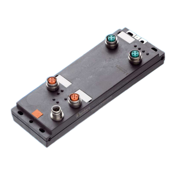
Page 8: Product Overview
Technical Manual LioN-Link PROFINET Product overview 3.1. 3.2. Module variants Part number Description I/O-connection Design LioN-Link BusHead 0940 ESL 601 BusHead PROFINET IO LioN-Link modules universal I/O digital 0942 UEM 600 8 In/Out universal 4xM12 0942 UEM 650 8 In/Out universal 8xM8 0942 UEM 700 16 In/Out universal... - Page 9 Technical Manual LioN-Link PROFINET Part number Description 0935 253 108/… M Connecting cable for LioN-Link line, double ended, with M12-plug, angled, 5-pole, A-coded and M12-socket, angled, 5-pole, A-coded Power supply RKT 5-228/… M Connecting cable for power supply, single ended, with M12-socket, straight, 5-pole, A-coded RKWT 5-228/…...
-
Page 10: Mounting
Technical Manual LioN-Link PROFINET Mounting 4.1. Outer dimensions Subject to change without notice! Version 1.2 / August 2014 Page 10 of 30... -
Page 11: Notes For The Field Installation
Technical Manual LioN-Link PROFINET 4.2. Notes for the field installation The modules are to be mounted on a flat surface, each with or at least with two screws. Type of mounting Screws Torque flat M4x30/35 1,0 Nm laterally M4x40/70 1,0 Nm With all types of mounting a flat washer according to DIN 125 has to be used. -
Page 12: Wiring
Technical Manual LioN-Link PROFINET Wiring 5.1. Pin assignments 5.1.1. PROFINET ports, M12-socket, 4-pole, D-coded Colour code of the connectors: green Connector Signal Function Transmit Data + Receive Data - PROFINET ports P1, P2 Transmit Data + Receive Data - ATTENTION, risk of destruction! Do not connect power supply lines (24 V DC) to the data lines. -
Page 13: Link System Connector, M12-Socket, 5-Pole
Technical Manual LioN-Link PROFINET 5.1.3. Link system connector, M12-socket, 5-pole Colour code of the connector: orange Connector Signal Function Drain Shield +24 V 24 V system / sensors System bus 0 V system / sensors Data + Data + Data - Data - The 24 V power supply in the bus connectors is used to energize the module electronics and the sensors of the system bus participants. -
Page 14: Intermediate Power Supply Feed On Lion-Link I/O-Modules
Technical Manual LioN-Link PROFINET 5.2. Intermediate power supply feed on LioN-Link I/O-modules During the planning of a machine or a plant it has to be considered that starting from certain cable lengths an intermediate power supply feed for the electronics and sensors of the I/O-modules can be necessary. If the power supply for the I/O-modules is not sufficient they deliver a diagnostics message. -
Page 15: Auxiliary Tool For The Determination Of The Voltage Drop And The Place Of The Intermediate Power Supply Feed
Technical Manual LioN-Link PROFINET 5.2.2. Auxiliary tool for the determination of the voltage drop and the place of the intermediate power supply feed. For the calculation of the voltage drop on the LioN-Link line a calculation table as a Microsoft Excel sheet is available under http://www.beldensolutions.com/en/Service/Downloadcenter/Software_Lumberg/index.phtml. -
Page 16: Configuring And Commissioning
Technical Manual LioN-Link PROFINET Configuring and commissioning The configuration and commissioning of the LioN-Link BusHead described on the following pages was accomplished with the STEP7 Siemens AG help of the -software of the . In case of using a control system from another controller supplier please attend to the associated documentation. -
Page 17: Step7
Technical Manual LioN-Link PROFINET 6.4. Configuration of the LioN-Link PROFINET system in STEP7 After the installation of the GSDML file for the BusHead the LioN-Link system is available in the hardware catalogue under PROFINET IO – Additional Field Devices - I/O - Lumberg LioN-Link First configure the control system in the usual way. -
Page 18: Assignment Of A Unique Device Name
Technical Manual LioN-Link PROFINET 6.4.1. Assignment of a unique device name PROFINET IO devices are addressed in PROFINET by a unique device name. The name can be assigned freely by the user but may only occur once in the network. HW-Config Edit –... -
Page 19: Device Exchange Without Removeable Media/Pg
Technical Manual LioN-Link PROFINET 6.4.3. Device exchange without removable media/PG PROFINET IO devices that support the function device exchange without removable media or PG can be exchanged in an existing PROFINET network without the need to use a removable media or programming device. In this case the IO-Controller takes over the task to assign the device name. - Page 20 Technical Manual LioN-Link PROFINET Subject to change without notice! Version 1.2 / August 2014 Page 20 of 30...
-
Page 21: The Parameter Interchanged Modules
Technical Manual LioN-Link PROFINET Notice! The replacement device must be in the delivery state (factory settings) for the exchange without removable media/PG. If necessary the factory settings have to be restored. 6.4.4. The parameter Interchanged Modules Object properties – Parameter The parameter settings can be reached via the menu item . -
Page 22: Prioritized Startup
Technical Manual LioN-Link PROFINET 6.4.5. Prioritized start-up The prioritized start-up is not supported by the BusHead. Therefore, the selection box Prioritized Start-up in the window Properties – Interface (X1) should not be selected. 6.4.6. Resetting the BusHead to factory settings STEP7, PLC –... -
Page 23: The Integrated Web Server
Technical Manual LioN-Link PROFINET The integrated web server The BusHead provides an integrated web server which offers functions for configuration, monitoring and diagnostics of the BusHead itself and the connected I/O-modules. With the help of a standard web browser it is possible to get access to the provided functions via an existing TCP/IP connection. For the use of the web server the BusHead needs an own IP address. -
Page 24: The Configuration Page (Configuration)
Technical Manual LioN-Link PROFINET The homepage gives an overview over the characteristics of the BusHead regarding system, LioN-Link and PROFINET. The system characteristics comprise information concerning the firmware versions, serial number and a counter (Rev. Counter), which is increased by one with each change of a parameter (IP-address, device name) on the BusHead. In the section „LioN Link Information “you find the number of connected I/O modules per line, the actual conditions of the two LioN Link lines and information concerning the presence of a diagnostics at a line. -
Page 25: The Monitoring Page (Monitoring)
Technical Manual LioN-Link PROFINET A firmware update of the two microcontrollers, which are used in this BusHead, is also possible on this side. The procedure is described in one of the following chapters of this manual and should be absolutely observed. 7.3. -
Page 26: Firmware Update
Technical Manual LioN-Link PROFINET Firmware update Over the configuration page of the integrated web server a firmware update of the two microcontrollers is possible, which are used in this BusHead. Important note! Please observe the following description of the firmware updates exactly since otherwise the BusHead cannot function properly any longer. -
Page 27: Alarm And Error Messages Of The Bushead
Technical Manual LioN-Link PROFINET Alarm and error messages of the BusHead If the BusHead detects an error condition, then it triggers an alarm message. The BusHead supports diagnostics alarms. Diagnostics alarms are released in case of periphery faults, like overload, short circuit and broken wire. If an I/O-module at a LioN-Link line is removed or if it is no longer accessible (module breakdown, connection disturbed, “pulling“... -
Page 28: Channel Diagnostics
Technical Manual LioN-Link PROFINET 9.2. Channel diagnostics For the representation of the diagnostics data records the block version 0x0100 and the format identification (USI, user Structure Identifier) 0x8000 is used. The error type in the 16-bit value “ChannelErrorType” is manufacturer specific and defined as follows: Bit number ChannelErrorType Number of line... -
Page 29: Technical Data
Technical Manual LioN-Link PROFINET Technical data 10.1. General data Degree of protection IP 67 (only with screwed connectors) Ambient temperature -10°C / +60°C Weight 800 g Housing material Vibration resistance 15 g / 5–500 Hz Shock resistance 50 g / 11 ms Torques: •... -
Page 30: Led Indicators
Technical Manual LioN-Link PROFINET 10.4. LED indicators green System-/ sensors power supply line 1 and/or. Line 2 available System-/ sensors power supply line 1 and/or. Line 2 missing green flashing Firmware update S1, S2 green Line 1 and/or line 2 active, data exchange with I/O-modules Incorrect configuration / modules permuted.
Need help?
Do you have a question about the Lumberg Automation 0970 ESL 601 and is the answer not in the manual?
Questions and answers