
Related Manuals for Belden Lumberg Automation 0940 ESL 611


Summary of Contents for Belden Lumberg Automation 0940 ESL 611
- Page 1 Technical manual EtherNet/IP™ – LioN-Link BusHead 0940 ESL 611 Technical manual LioN-Link BusHead EtherNet/IP™ Technical support Release 1.1 04/2016 support-automation@belden.com...
- Page 2 Technical manual LioN-Link BusHead EtherNet/IP™ Release 1.1 04/2016...
-
Page 3: Table Of Contents
Contents Contents About this manual General information Explanation of symbols 1.2.1 Use of danger information 1.2.2 Use of general information Version information Safety instructions Intended use Qualified personnel System description About the LioN Link module series Product overview 3.2.1 Module overview Assembly and wiring General information Wiring... - Page 4 IP address The integrated web server Login The Home page The Configuration page (Config) 6.3.1 Scan bus 6.3.2 Load from Device 6.3.3 Save to Device 6.3.4 Load Config from File 6.3.5 Save Config to File 6.3.6 Settings 6.3.7 Address Table 6.3.8 LioN Link EtherNet/IP Offline Configurator The Status page The System page...
- Page 5 Acyclic services 8.8.1 Acyclic diagnostic object 8.8.2 Acyclic configuration 0942 UEM 783 Technical data General Electrical properties 9.2.1 Power supply 9.2.2 LioN Link bus system 9.2.3 EtherNet/IP Ambient conditions LEDs Declaration of conformity Accessories Technical manual LioN-Link BusHead EtherNet/IP™ Release 1.1 04/2016...
- Page 6 Contents Technical manual LioN-Link BusHead EtherNet/IP™ Release 1.1 04/2016...
-
Page 7: About This Manual
Fax +49 (0) 23 55 / 5044-333 support-automation@belden.com www.lumberg-automation.com Belden Deutschland GmbH – Lumberg Automation™ – reserves the right to make technical changes or changes to this manual at any time without notice. Technical manual LioN-Link BusHead EtherNet/IP™ Release 1.1 04/2016... -
Page 8: Explanation Of Symbols
About this manual 1.2 Explanation of symbols Explanation of symbols 1.2.1 Use of danger information Danger information is denoted as follows: DANGER Means that death, serious physical injury or substantial damage to property will occur if the required safety measures are not taken. WARNING Means that death, serious physical injury or substantial damage to property can occur if the required safety measures are not taken. -
Page 9: Version Information
About this manual 1.3 Version information Version information Index Created Changed Changed Version number Version 1.0 Version 1.1 Date September 2015 April 2016 Name/department R&D Lieb/Jung R&D Lieb/Jung Table 1: Overview of manual revisions Technical manual LioN-Link BusHead EtherNet/IP™ Release 1.1 04/2016... - Page 10 About this manual 1.3 Version information Technical manual LioN-Link BusHead EtherNet/IP™ Release 1.1 04/2016...
-
Page 11: Safety Instructions
Safety instructions 2.1 Intended use Safety instructions Intended use The LioN Link BusHead EtherNet/IP devices described in this manual are decentralized input/output assemblies in an EtherNet/IP network. We adhere to all safety standards when developing, producing, testing, and documenting our products. When you adhere to the handling specifications and safety instructions described for the configuration, assembly, and correct operation, there should not normally be any risks for people or equipment. -
Page 12: Qualified Personnel
Only Belden Deutschland GmbH – Lumberg Automation™ – is permitted to make changes to the hardware or software of the products that go beyond the scope of this manual. - Page 13 Safety instructions 2.2 Qualified personnel WARNING Making unqualified changes to the hardware or software, or non-adherence to the warning information contained in this manual, can result in serious personal injury or damage to equipment. Technical manual LioN-Link BusHead EtherNet/IP™ Release 1.1 04/2016...
- Page 14 Safety instructions 2.2 Qualified personnel Technical manual LioN-Link BusHead EtherNet/IP™ Release 1.1 04/2016...
-
Page 15: System Description
System description 3.1 About the LioN Link module series System description About the LioN Link module series LioN (Lumberg I/O Network) Link is a modular system for decentralized use in a rough industrial environment for easy handling of the I/O data in a superordinate EtherNet/IP network. -
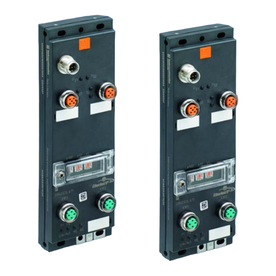
Page 16: Product Overview
System description 3.2 Product overview Product overview 3.2.1 Module overview Item number Description I/O connection Design BusHead 0940 ESL 611 BusHead SAP number: 934 815-001 EtherNet/IP LioN Link module Universal I/O digital 0942 UEM 600 8 In/out universal 4 x M12 SAP number: 92356 0942 UEM 650... - Page 17 System description 3.2 Product overview Item number Description I/O connection Design LioN Link custom modules 0941 UNC 601 Power distributor 4 x M12 SAP number: 96720 0942 UEM 783 Motion drive 8 x M12 SAP number: 102163 control Table 2: Overview of LioN Link modules Technical manual LioN-Link BusHead EtherNet/IP™...
- Page 18 System description 3.2 Product overview Technical manual LioN-Link BusHead EtherNet/IP™ Release 1.1 04/2016...
-
Page 19: Assembly And Wiring
Assembly and wiring 4.1 General information Assembly and wiring General information Mount the module on a level surface with at least 2 screws. Use washers for all fastening methods as per DIN 125. Fastening method Screw Tightening torque Flat M4 ×... -
Page 20: Wiring
Assembly and wiring 4.2 Wiring Wiring Observe the following specifications to ensure the best possible immunity and emission level of the LioN Link system: Use only shielded Can/DeviceNet thin-hybrid cables for LioN Link bus connections. Use at least shielded CAT 5e cable for EtherNet bus connections. ... -
Page 21: Outer Dimensions
Assembly and wiring 4.3 Outer dimensions Outer dimensions Figure 1: Outer dimensions Technical manual LioN-Link BusHead EtherNet/IP™ Release 1.1 04/2016... -
Page 22: Port Assignments
Assembly and wiring 4.4 Port assignments Port assignments All the contact arrangements shown in this chapter show the frontal view of the connection area for the connectors. 4.4.1 Connection assignment Figure 2: Connection assignment 4.4.2 Power supply M12 connector, 5-pin, A-coded ... -
Page 23: Lion Link
Assembly and wiring 4.4 Port assignments Figure 3: Port assignment voltage supply Signal Function 1, 2 (bridged) +24V DC Module power supply + 3, 4 (bridged) GND 0V Module power supply - Functional ground Table 4: Port assignment voltage supply CAUTION Risk of destruction! Never connect the power supply to the data cables. -
Page 24: Addressing Window
Assembly and wiring 4.4 Port assignments Figure 4: Port assignment LioN Link Signal Function DRAIN Shield +24V DC Subbus line 1 or 2 – module power supply + 0V GND Subbus line 1 or 2 – module power supply - DATA+ LioN Link data communication + DATA-... -
Page 25: Functional Ground
Assembly and wiring 4.4 Port assignments Figure 5: Port assignment EtherNet Signal Function TD + Transmit data plus RD + Receive data plus TD - Transmit data minus RD - Receive data minus Table 6: Port assignment EtherNet NOTE All M12 metal sleeves are electrically connection via functional ground. 4.4.6 Functional ground Information on the reference earth is provided in the assembly instructions... -
Page 26: T-Distributors For Intermediate Power Feed
Figure 6: T-distributors for intermediate power feed 4.4.9 Voltage drop and intermediate power feed To calculate the expected voltage drop and location for the intermediate power feed, Belden provides a calculation table as an XLS file in its download area: http://www.beldensolutions.com/en/Service/download_center/ Technical manual LioN-Link BusHead EtherNet/IP™... - Page 27 Assembly and wiring 4.4 Port assignments The table determines the voltage drop in the line based on the power draw of the I/O modules and the sensor system, as well as the cable lengths and cable diameters for the LioN Link lines. Parallel to this, the table names the I/O module that requires an intermediate power feed.
- Page 28 Assembly and wiring 4.4 Port assignments Technical manual LioN-Link BusHead EtherNet/IP™ Release 1.1 04/2016...
-
Page 29: Starting Operation
Electronic Data Sheet (EDS) An EDS file is required for the configuration of a module in the control system. Download the EDS file from the Belden Web page, or request the EDS file from the Support Team. The website address for the download is: http://www.beldensolutions.com/en/Service/download_center/... -
Page 30: Ip Address
Starting operation 5.3 IP address IP address In delivery condition and after resetting to factory defaults, automatic configuration of the network address via DHCP (Dynamic Host Configuration Protocol) is set. The module retrieves the IP address and subnet mask from the DHCP server. - Page 31 Starting operation 5.3 IP address The following settings are possible via the rotary encoding switch: Rotary switch setting Function 000 In the state on delivery, the DHCP function is activated. The (state on delivery) module first requests the network parameters via DHCP. The network parameters are not saved, but the integrated web server can be used to save them.
- Page 32 Starting operation 5.3 IP address Technical manual LioN-Link BusHead EtherNet/IP™ Release 1.1 04/2016...
-
Page 33: The Integrated Web Server
The integrated web server 6.1 Login The integrated web server The BusHead provides an integrated web server for configuration, monitoring and diagnostics. You have the option of accessing the websites stored on it by entering the address in a web browser. Internet Explorer version 10 or newer is supported. -
Page 34: The Home Page
The integrated web server 6.2 The Home page The Home page This page is the starting point for accessing the integrated web server. The Configuration page (Config) In the "Stored Configuration" list, the integrated web server displays the modules planned in the BusHead. You can plan the target configuration by selecting the I/O modules in column "module"... -
Page 35: Scan Bus
The integrated web server 6.3 The Configuration page (Config) 6.3.1 Scan bus Clicking this button reboots the connected I/O modules. Subsequently, the BusHead compares the actual configuration with the previously stored target configuration. The actual configuration is shown in column "Scanned", while the existing differences to the stored target configuration are marked in red. -
Page 36: Load From Device
The integrated web server 6.3 The Configuration page (Config) The actual configuration can be adopted as the target configuration by pressing the "transfer" button. The configuration is adopted by clicking the "Save to Device" button. 6.3.2 Load from Device Pressing this button queries the current module configuration/parameterization. -
Page 37: Load Config From File
The integrated web server 6.3 The Configuration page (Config) 6.3.4 Load Config from File Pressing this button loads a saved configuration file from an external storage medium (e.g., PC or network drive) on the BusHead. If you need to replace the BusHead, this option gives you the ability to restore previously saved configurations. - Page 38 The integrated web server 6.3 The Configuration page (Config) After determining the final configuration, this setting should then be changed to "Do not accept" in order to detect swapping of I/O modules or the wiring immediately and check for the correct structure. This setting is not mandatory, since error-free operation of the system and the replacement of defective modules is possible in "Accept"...
-
Page 39: Address Table
The integrated web server 6.3 The Configuration page (Config) 6.3.7 Address Table The "Address Table" button opens the following window. The "IO address table" table shows the address at which the data can be found for the respective modules. The current address table illustrates by way of example that a total of 62 bytes of data are sent from the BusHead to the controller. -
Page 40: Lion Link Ethernet/Ip Offline Configurator
The integrated web server 6.4 The Status page 6.3.8 LioN Link EtherNet/IP Offline Configurator An Offline Configurator for configuring a LioN Link EtherNet/IP system without hardware is available on http://www.beldensolutions.com/en/Service/download_center/. This can used to create a LioN-Link configuration file that can be loaded onto a BusHead. - Page 41 The integrated web server 6.4 The Status page On this page the embedded web server shows you the "Diagnostic Status" of the LioN Link system. The left table lists the existing module configuration. Modules that report diagnostics are shown in red in the "Dia" column (with existing diagnostic message), yellow (without existing diagnostic message) or gray (diagnostics inactive)....
-
Page 42: The System Page
The integrated web server 6.5 The System page The System page 6.5.1 General Information In this table, the embedded web server shows you the current system information for the device. The "Firmware" section contains information about the software version, while the "Device" section contains the serial number and manufacturing date. -
Page 43: Change Ip-Configuration
The integrated web server 6.5 The System page Status Description 100M / Half 100 MBit/s, half-duplex 100M / Full 100 MBit/s, full duplex Table 8: Status of the two LAN interfaces The "Network" section displays the network settings of the LAN interfaces. 6.5.2 Change IP-Configuration This table gives you the option of changing the network settings for the two... -
Page 44: Restart Device
The integrated web server 6.5 The System page Clicking the "Submit" button saves the IP configuration settings in the BusHead. The settings are applied the next time you restart. 6.5.3 Restart device Restart lets you restart the BusHead. All connections are interrupted! To reboot, check the box and click the "Restart"... - Page 45 The integrated web server 6.5 The System page Perform a power on reset of the BusHead by briefly interrupting the power supply. Before you start the firmware update, make sure that the power supply will not be interrupted during the update process. The two green LEDs "US1"...
-
Page 46: The User Page
The integrated web server 6.6 The User page The User page On this page, the integrated web server shows you an overview of the user accounts you have set up. User accounts can only be edited after logging in with your username "admin" or as a user with "Permissions" = "Admin". The default password for the "admin"... -
Page 47: The Contact Page
The integrated web server 6.7 The Contact page To delete a user account, click the button in the "Del" column. Read permissions do not exist. All users with access to the website are allowed to read data. NOTE The "admin"... - Page 48 The integrated web server 6.7 The Contact page Technical manual LioN-Link BusHead EtherNet/IP™ Release 1.1 04/2016...
-
Page 49: Bit Assignment
Bit assignment 7.1 Input data – Assembly instance Bit assignment The LioN Link BusHead uses assembly instances to exchange cyclical I/ data. The BusHead supports: Assembly instance 101 for inputs and Assembly instance 100 for outputs. The BusHead provides 2 bytes of input 2 bytes of output data. These data act as status and control bytes for special functions (diagnose acknowledge, transmission of acyclical parameter data, etc.). -
Page 50: Outputdaten - Assembly Instance 100
Bit assignment 7.2 Outputdaten - Assembly Instance Byte Data UEM630 Ch. 3, Analog in low byte UEM630 Ch. 3, Analog in high byte UEM630 Ch. 4, Analog in low byte UEM630 Ch. 4, Analog in high byte UEM601 8 Digital In Stuff byte UEM701 16 Digital in low byte UEM701 16 Digital in high byte... - Page 51 Bit assignment 7.2 Outputdaten - Assembly Instance Byte Data UEM630 Ch. 1, Analog out low byte UEM630 Ch. 1, Analog out high byte UEM630 Ch. 2, Analog out low byte UEM630 Ch. 2, Analog out high byte UEM630 Ch. 3, Analog out low byte UEM630 Ch.
- Page 52 Bit assignment 7.2 Outputdaten - Assembly Instance Technical manual LioN-Link BusHead EtherNet/IP™ Release 1.1 04/2016...
-
Page 53: Diagnostics Processing
Diagnostics processing Diagnostics processing To facilitate troubleshooting, the BusHead supports comprehensive diagnostics behavior. Signaling occurs through LEDs on the BusHead, see chapter “LEDs” on page through the integrated web server and coded as a block, which is appended to the cyclic data, see chapter “Input data –... -
Page 54: Diagnostic Settings On The Bushead
Diagnostics processing 8.1 Diagnostic settings on the BusHead Diagnostic settings on the BusHead On the web server's "Config" Page, you can configure the following diagnostics settings for the default settings shown for the BusHead in the "Edit" column. 8.1.1 Diagnostic Acknowledge Diagnostic Acknowledge Disabled ... -
Page 55: Cyclic Diagnostic Data
Diagnostics processing 8.2 Cyclic diagnostic data Cyclic diagnostic data The BusHead sends two status bytes as "Producing data" appended to the I/O module data and, depending on the parameterization, two or six diagnostic blocks of four bytes (I/O address table in chapter 6.3.7). It receives two control bytes as "consuming data"... -
Page 56: Cyclic Bushead Diagnostic Blocks
Diagnostics processing 8.3 Diagnostic Codes 8.2.3 Cyclic BusHead diagnostic blocks Depending on the configuration, the BusHead sends 2 or 6 diagnostic blocks as "producing data" appended to the two BusHeads status bytes (see “Address Table” on page 35). The diagnostic blocks are defined as follows: Byte no.: Description Last Octet of IP Address (Value: 0- 255) Bit 7-4: Sub-Link Info: BusHead = 0, Link 1 = 1, Link 2 = 2, Link 1 &... -
Page 57: Behavior In Case Of A Diagnostic Overflow
Diagnostics processing 8.4 Behavior in case of a diagnostic overflow Diagnostic Description Code 0x12 I/O module failure 0x13 Diagnostics I/O module 0x14 Configuration fault (Use Web-Interface for detailed information) 0x15 Common I/O fault 0x16 Over current motor 0x17 Common motor fault 0x18 Internal module fault 0x19... -
Page 58: Diagnostic Sequence In None Acknowledge Mode
Diagnostics processing 8.5 Diagnostic sequence in None Acknowledge Mode The restriction applies for all diagnostic modules that the diagnostic blocks of diagnoses which have become inactive are not available for new diagnostic messages until all other reported diagnoses have become inactive. Any diagnoses that have occurred in the meantime are displayed on web server as module diagnoses, indicated via the LEDs, or can be read acyclically from the BusHead using Class ID 0x64 / instance 1 / attribute 1. - Page 59 Diagnostics processing 8.6 Diagnostic sequence in Acknowledge Mode Because the administrator has not yet acknowledged the diagnosis (Acknowledge pending), the outgoing diagnostic information is stored on the BusHead. The administrator acknowledges the diagnosis by setting the corresponding BusHead control bit to 1. ...
-
Page 60: Programming Acknowledge Mode In The User Program
Diagnostics processing 8.7 Programming Acknowledge mode in the user program Programming Acknowledge mode in the user program NOTE The following program sequence acts as an example for creating the PLC program using the BusHead status byte 0 and control byte 0. Technical manual LioN-Link BusHead EtherNet/IP™... -
Page 61: Acyclic Services
Diagnostics processing 8.8 Acyclic services Acyclic services In addition to cyclic communication, there is also the possibility to exchange Technical manual LioN-Link BusHead EtherNet/IP™ Release 1.1 04/2016... -
Page 62: Acyclic Diagnostic Object
Diagnostics processing 8.8 Acyclic services data via acyclic objects. 8.8.1 Acyclic diagnostic object In the case of an overflow of the diagnostic blocks or failure of one or more I/O modules, diagnostic information can always be read from the BusHead via the Class ID 0x64 / instance 1 / attribute 1.... -
Page 63: Acyclic Configuration 0942 Uem 783
Diagnostics processing 8.8 Acyclic services Byte Bit 7 Bit 6 Bit 5 Bit 4 Bit 3 Bit 2 Bit 1 Bit 0 CFG CFG CFG CFG CFG CFG CFG not S1-M7 S1-M6 S1-M5 S1-M4 S1-M3 S1-M2 S1-M1 used CFG CFG CFG... - Page 64 Diagnostics processing 8.8 Acyclic services Successful transmission of the parameter data to a 0942 UEM 783 module is indicated by the MSG Instruction "Done". Any number of connected modules can be configured with this command. Bit 0 is used in status byte 1/control byte 1 in each case to report the status and control parameterization.
-
Page 65: Technical Data
Technical data 9.1 General Technical data General Protection class IP 67 (only when the connectors are screwed in or when protective caps are used) Ambient temperature -10 °C to +60 °C (+14 °F to +140 °F) Weight 220 g Housing material Torques: Fastening screws M4 1.0 Nm... -
Page 66: Ethernet/Ip
Technical data 9.3 Ambient conditions 9.2.3 EtherNet/IP Physical transmission As per IEEE 802.3 10-BASE-T 100-BASE-TX Transmission rate 10 Mbit/s 100 Mbit/s Electric isolation 500 V (M12-d-coded) Between the bus cable and the electronics Table 20: Information on EtherNet/IP Ambient conditions Ambient temperature -10 °C to +60 °C Protection class... - Page 67 Technical data 9.4 LEDs Green Device ready for operation Flashing green Device is not configured, or incorrect configuration Flashing red Firmware update Flashing red/green Device is performing a self-test Device off Green Connected to a master Flashing green IP address exists, but no connection to a master IP address occupied by another device Flashing red Connection timeout...
- Page 68 Technical data 9.4 LEDs Technical manual LioN-Link BusHead EtherNet/IP™ Release 1.1 04/2016...
-
Page 69: 10 Declaration Of Conformity
Declaration of conformity 10 Declaration of conformity Technical manual LioN-Link BusHead EtherNet/IP™ Release 1.1 04/2016... - Page 70 Declaration of conformity Technical manual LioN-Link BusHead EtherNet/IP™ Release 1.1 04/2016...
-
Page 71: 11 Accessories
Accessories 11 Accessories Item number Description EtherNet/IP 0985 342 100/… M Connection cable for EtherNet/IP, assembled on both sides with M12 connectors, straight, 4-pin, D-coded 0985 342 102/… M Connection cable for EtherNet/IP, assembled on one side with an M12 connector, straight, 4-pin, D-coded 0985 342 104/…... - Page 72 Accessories Item number Description 0986 EMC 102 Configurable M12 connector for EtherNet/IP cable, straight, 4-pin, D- coded with spring type terminal RSC 5/9 Configurable M12 connector for LioN Link line and power supply, straight, 5-pin, A-coded RSCW 5/9 Configurable M12 connector for LioN Link line and power supply, angled, 5-pin, A-coded RKC 5/9 Configurable M12 socket for LioN Link line and power supply, straight,...
Need help?
Do you have a question about the Lumberg Automation 0940 ESL 611 and is the answer not in the manual?
Questions and answers