Table of Contents
Advertisement
Quick Links
Manual
CC-Link IE Field Basic
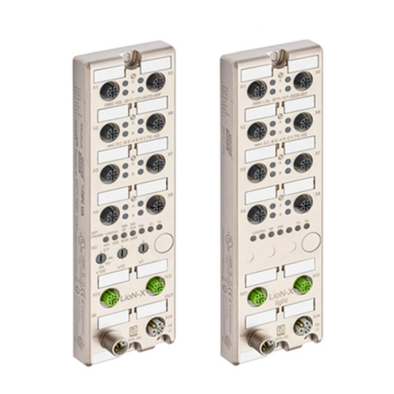
LioN-X IO-Link Master Multiprotocol:
0980 XSL 3912-121-007D-01F (8 x IO-Link Class A)
0980 XSL 3913-121-007D-01F (8 x IO-Link Class A/B Mixmodule)
LioN-Xlight IO-Link Master CC-Link IE Field Basic:
0980 LSL 3411-121-0006-010 (8 x IO-Link Class A)
0980 LSL 3410-121-0006-010 (4 x IO-Link Class A + 8 x DI)
Manual CC-Link IE Field Basic
Technical Support
Version 1.4 07/2023
lumberg-automation-support.belden.com
Advertisement
Table of Contents

Related Manuals for Belden Lumberg Automation LioN-X 0980 XSL 3912-121-007D-01F


Summary of Contents for Belden Lumberg Automation LioN-X 0980 XSL 3912-121-007D-01F
- Page 1 0980 XSL 3913-121-007D-01F (8 x IO-Link Class A/B Mixmodule) LioN-Xlight IO-Link Master CC-Link IE Field Basic: 0980 LSL 3411-121-0006-010 (8 x IO-Link Class A) 0980 LSL 3410-121-0006-010 (4 x IO-Link Class A + 8 x DI) Manual CC-Link IE Field Basic Technical Support Version 1.4 07/2023 lumberg-automation-support.belden.com...
-
Page 2: Table Of Contents
Contents Contents 1 About this manual 1.1 General information 1.2 Explanation of symbols 1.2.1 Use of danger information 1.2.2 Use of general information 1.3 Version information 2 Safety instructions 2.1 Intended use 2.2 Qualified personnel 3 Designations and synonyms 4 System description 4.1 About LioN-X and LioN-Xlight 4.2 Device variants 4.3 I/O port overview... - Page 3 Contents 6 Assembly and wiring 6.1 General information 6.2 Outer dimensions 6.2.1 LioN-X multiprotocol variants with CC-Link IE Field Basic 6.2.2 LioN-Xlight variants with CC-Link IE Field Basic 6.2.3 Notifications 6.3 Port assignments 6.3.1 Ethernet ports, M12 socket, 4-pin, D-coded 6.3.2 Power supply with M12 power L-coded 6.3.2.1 IO-Link Master with Class A ports 6.3.2.2 IO-Link Master with Class A/B ports...
- Page 4 Contents 8.1.6 External configuration lock 8.2 Port configuration X1 .. X8 8.2.1 Port Mode 8.2.2 Validation and Backup 8.2.3 IQ Mode 8.2.4 Cycle Time 8.2.5 Vendor ID 8.2.6 Device ID 8.2.7 IOL Failsafe 8.2.8 IOL Failsafe values 8.2.9 Swapping Length 8.2.10 Swapping Offset 8.2.11 Swapping Count 8.2.12 Sensor Supply Disabled...
- Page 5 Contents 10.3 Overload/short circuit of the digital outputs 10.4 Overload/short circuit of the actuator power supply P24 10.5 Overload/short-circuit of the I/O port sensor supply outputs Configuration operation with ® GxWorks3 11.1 Integration of a CSP+ file 11.2 Network parameters 11.3 Parameter processing 12 IIoT functionality 12.1 MQTT...
- Page 6 Contents 12.3.6 Example: Writing ISDU 12.4 CoAP server 12.4.1 CoAP configuration 12.4.2 REST API access via CoAP 12.4.3 CoAP configuration - Quick start guide 12.4.3.1 CoAP configuration via JSON 12.5 Syslog 12.5.1 Syslog configuration 12.5.2 Syslog configuration - Quick start guide 12.5.2.1 Syslog configuration via JSON 12.6 Network Time Protocol (NTP) 12.6.1 NTP configuration...
- Page 7 Contents 15 Technical data 15.1 General 15.2 CC-Link IE Field Basic protocol 15.3 Power supply of the module electronics/sensors 15.4 Power supply of the actuators 15.4.1 IO-Link Class A devices (U 15.4.2 IO-Link Class A/B devices (U 15.5 I/O ports Channel A (Pin 4) 15.5.1 Configured as digital input, Ch.
-
Page 8: About This Manual
Im Gewerbepark 2 D-58579 Schalksmühle Germany lumberg-automation-support.belden.com www.lumberg-automation.com catalog.belden.com Belden Deutschland GmbH – Lumberg Automation™ – reserves the right to make technical changes or changes to this document at any time without notice. Manual CC-Link IE Field Basic Version 1.4 07/2023... -
Page 9: Explanation Of Symbols
1 About this manual 1.2 Explanation of symbols 1.2 Explanation of symbols 1.2.1 Use of danger information Danger information is denoted as follows: Danger: Means that death, serious physical injury or substantial damage to property will occur if the required safety measures are not taken. -
Page 10: Version Information
1.3 Version information 1 About this manual 1.3 Version information Index Created Changes 03/2022 06/2022 Temporarily excluded device variant information for 0980 XSL 3913-121-007D-01F (shipping in 2023) 10/2022 Device variant information for 0980 XSL 3913-121-007D-01F included. Ch. 7.4: LED description 12/2022 Ch. -
Page 11: Safety Instructions
2 Safety instructions 2.1 Intended use 2 Safety instructions 2.1 Intended use The products described in this manual are decentralized IO-Link Masters on an Industrial Ethernet Network. We adhere to all safety standards when developing, producing, testing, and documenting our products. When you adhere to the handling specifications and safety instructions described for the configuration, assembly, and correct operation, there should not normally be any risks for people or equipment. -
Page 12: Qualified Personnel
Only Belden Deutschland GmbH – Lumberg Automation™ – is permitted to make changes to the hardware or software of the products that go beyond the scope of this manual. -
Page 13: Designations And Synonyms
3 Designations and synonyms 3 Designations and synonyms Add-On Instruction Application Programming Interface Bus Fault LED Big Endian Data format with High-B on first place (PROFINET and IO-Link) Back-Up Inconsistency (EIP diagnostics) CC-Link IE Field I/O port pin 4 mode, IO-Link communication/switching signal Ch. - Page 14 3 Designations and synonyms Functional Earth Force Mode Enabled (EIP diagnostics) Functional Safety Fast Start-Up GSDML General Station Description Markup Language High-B High-Byte IO-Link port COM Error (EIP diagnostics) Invalid Cycle Time (EIP diagnostics) IO-Link port Device Error (EIP diagnostics) IO-Link port Device Notification (EIP diagnostics) IO-Link port Device Warning (EIP diagnostics) IIoT...
- Page 15 3 Designations and synonyms Least Significant Bit Low Voltage Actuator Supply (EIP diagnostics) Low Voltage System/Sensor Supply (EIP diagnostics) Management Information Base Multiprotocol: PROFINET + EtherNet/IP + EtherCAT ® Modbus TCP (+ CC-Link IE Field Basic) MQTT Message Queuing Telemetry Transport (open networking protocol) Most Significant Bit Metric thread according to DIN 13-1 with 12 mm diameter...
- Page 16 3 Designations and synonyms Single Protocol (PROFINET, EtherNet/IP, EtherCAT ® Modbus TCP or CC-Link IE Field Basic) Startup Parameterization Error (EIP diagnostics) Test Channel B Test Channel A , supply voltage for the load circuit (Actuator supply on Auxiliary Class B ports of Class A/B IO-Link Master) User Datagram Protocol User-Defined Data Types UINT8...
-
Page 17: System Description
Use all benefits of the Lumberg Automation product solution by additionally ™ downloading the configuration tool LioN-Management Suite V2.0 from www.belden.com to enable e.g. a fast and easy parameterization of the connected IO-Link devices via the embedded IODD interpreter. Manual CC-Link IE Field Basic... -
Page 18: Device Variants
4.2 Device variants 4 System description 4.2 Device variants The following variants are available in the LioN-X and the LioN-Xlight family: Article Product designation Description I/O port functionality number 935700001 0980 XSL 3912-121-007D-00F LioN-X M12-60 mm, 8 x IO-Link Class A IO-Link Master Multiprotocol (PN, EIP, EC, MB) - Page 19 4 System description 4.2 Device variants Article Product designation Description I/O port functionality number 935701003 0980 LSL 3211-121-0006-004 LioN-Xlight M12-60 mm, 8 x IO-Link Class A IO-Link Master EtherCAT ® 935702003 0980 LSL 3210-121-0006-004 LioN-Xlight M12-60 mm, 4 x IO-Link Class A IO-Link Master + 8 x DI EtherCAT...
-
Page 20: I/O Port Overview
4.3 I/O port overview 4 System description 4.3 I/O port overview The following tables show the main I/O port differences of the LioN-X IO-Link Master family. Pin 4 and Pin 2 of the I/O ports can be configured partly to IO-Link, Digital Input or Digital Output. LioN-X Class A IO-Link ports Device Port... - Page 21 4 System description 4.3 I/O port overview LioN-X Class A/B IO-Link ports Device Port Pin 4 / Ch. A (C/Q) Pin 2 / Ch. B (I/Q) variant Info: 4 x Class A Type 1 Supply Supply Type 1 Supply Supply –...
- Page 22 4.3 I/O port overview 4 System description LioN-Xlight Class A IO-Link ports Device variant Port Pin 1 U Pin 4 / Ch. A (C/Q) Pin 2 / Ch. B (I/Q) Info: Class A Type 1 Type 1 – Supply by U Out (2 A) DO (0.5 A*) Out (2 A)
-
Page 23: Overview Of Product Features
5 Overview of product features 5.1 CC-Link IE Field Basic product features 5 Overview of product features 5.1 CC-Link IE Field Basic product features CC-Link IE Field Basic network Number of stations: 4 (2 for device variant 0980 LSL 3410-121-0006-010). RX –... -
Page 24: I/O Port Features
5.2 I/O port features 5 Overview of product features 5.2 I/O port features IO-Link specification. LioN-X is ready for IO-Link specification v1.1.3. 8 x IO-Link Master ports Depending on the device variant, the device has 4 IO-Link Class A ports, 4 IO-Link Class A ports and 4 IO-Link Class B ports, or 8 IO-Link Class A ports with an additional digital input and optional output (0980 XSL 3x13... -
Page 25: Integrated Web Server
5 Overview of product features 5.3 Integrated Web server 5.3 Integrated Web server Network parameter display Get an overview of network parameters such as the IP address, subnet mask and gateway. Displaying diagnostics View diagnostics via the integrated Web server. User management Use the integrated Web server for convenient management of all users. -
Page 26: Security Features
5.4 Security features 5 Overview of product features 5.4 Security features Firmware signature The official firmware update packages contain a signature which helps prevent the system against manipulated firmware updates. Syslog The LioN-X multiprotocol variants support the traceability of messages centrally managed and logged via Syslog. -
Page 27: Other Features
5 Overview of product features 5.5 Other features 5.5 Other features Interface protection The devices have reverse polarity, short-circuit and overload protection for all interfaces. For more details, see section Port assignments on page 34. Failsafe The devices support a failsafe function. This allows you to define the behavior of every single channel configured as an output in the case of a loss of the PLC communication. -
Page 28: Assembly And Wiring
6.1 General information 6 Assembly and wiring 6 Assembly and wiring 6.1 General information Mount the device on a flat surface using 2 screws (M4x 25/30). The torque required here is 1 Nm. Use washers for all fastening methods as per DIN 125. Attention: The devices have a ground connection with an M4 thread for the conduction of interference currents and the EMC immunity. -
Page 29: Outer Dimensions
6 Assembly and wiring 6.2 Outer dimensions 6.2 Outer dimensions 6.2.1 LioN-X multiprotocol variants with CC-Link IE Field Basic Figure 1: 0980 XSL 3912-121-007D-01F Manual CC-Link IE Field Basic Version 1.4 07/2023... - Page 30 6.2 Outer dimensions 6 Assembly and wiring Figure 2: 0980 XSL 3913-121-007D-01F Manual CC-Link IE Field Basic Version 1.4 07/2023...
-
Page 31: Lion-Xlight Variants With Cc-Link Ie Field Basic
6 Assembly and wiring 6.2 Outer dimensions 6.2.2 LioN-Xlight variants with CC-Link IE Field Basic Figure 3: 0980 LSL 3411-121-0006-010 Manual CC-Link IE Field Basic Version 1.4 07/2023... - Page 32 6.2 Outer dimensions 6 Assembly and wiring Figure 4: 0980 LSL 3410-121-0006-010 Manual CC-Link IE Field Basic Version 1.4 07/2023...
-
Page 33: Notifications
6 Assembly and wiring 6.2 Outer dimensions 6.2.3 Notifications Attention: For UL applications, be sure to use a UL-certified cable with a suitable evaluation to connect the devices (CYJV or PVVA). To program the control, please refer to the OEM information, and only use suitable accessories. -
Page 34: Port Assignments
6.3 Port assignments 6 Assembly and wiring 6.3 Port assignments All the contact arrangements shown in this chapter show the frontal view of the connection area for the connectors. 6.3.1 Ethernet ports, M12 socket, 4-pin, D-coded Color coding: green Figure 5: Schematic drawing, ports X01, X02 Port Signal Function... -
Page 35: Power Supply With M12 Power L-Coded
6 Assembly and wiring 6.3 Port assignments 6.3.2 Power supply with M12 power L-coded Color coding: gray Figure 6: Schematic diagram of the M12 L-coding (connector X03 for Power Figure 7: Schematic diagram of the M12 L-coding (socket X04 for Power Out) Manual CC-Link IE Field Basic Version 1.4 07/2023... -
Page 36: Io-Link Master With Class A Ports
6.3 Port assignments 6 Assembly and wiring 6.3.2.1 IO-Link Master with Class A ports Power supply Signal Function (+24 V) Sensor/system power supply GND_U Ground/reference potential U GND_U Ground/reference potential U (+24 V) Load supply (NOT electrically isolated to U internally in device) Functional ground Table 9: Power supply with M12-Power Class A... -
Page 37: Io-Link Master With Class A/B Ports
6 Assembly and wiring 6.3 Port assignments 6.3.2.2 IO-Link Master with Class A/B ports Power supply Signal Function Mixed IO-Link (+24 V) Sensor/system power supply (Class A/B) I/O GND_U Ground/reference potential U ports (electrically isolated to GND_U internally in device) GND_U Ground/reference potential U (+24 V) -
Page 38: Io-Link Ports (Class A And Class B)
6.3 Port assignments 6 Assembly and wiring 6.3.3.1 IO-Link ports (Class A and Class B) Signal Function 0980 XSL 3x12-121... IO-Link Class A, ports +24 V power supply +24 V X1 .. X8 IN/OUT Ch. B: Digital input or digital output Ground/reference potential Ch. - Page 39 6 Assembly and wiring 6.3 Port assignments 0980 LSL 3x10-121... Signal Function IO-Link Class A, ports +24 V power supply +24 V X1 .. X4 Ch. B: Digital input Ground/reference potential Ch. A: IO-Link data communication, digital input or digital output n.c.
-
Page 40: Starting Operation
The CSP+ file and the associated icons are grouped together in an archive file named "0x4DF_0980 XSL 3912-121-007D-01F_1.0_en.CSPP.zip". "0xDF" stands for the vendor ID of Belden Deutschland GmbH, "0980 XSL 3912-121-007D-01F" is the model number of the LioN-X variant. Download this file and install it as described in chapter... -
Page 41: State On Delivery
7 Starting operation 7.3 State on delivery 7.3 State on delivery CC-Link IE Field Basic parameters in state on delivery or after a factory reset: Network mode: Static Static IP address: 192.168.3.XXX (XXX = rotary switch position or last stored data) Subnet mask: 255.255.255.0 Gateway address... -
Page 42: Setting The Rotary Encoding Switches
7.4 Setting the rotary encoding 7 Starting operation switches 7.4 Setting the rotary encoding switches The following LioN-X IO-Link Master variants support multiprotocol application for the protocols EtherNet/IP (E/IP), PROFINET (P), EtherCAT ® (EC) and Modbus TCP (MB): 0980 XSL 3912-121-007D-00F The following LioN-X IO-Link Master variants additionally provide the protocol CC-Link IE Field Basic (CC): 0980 XSL 3912-121-007D-01F... - Page 43 7 Starting operation 7.4 Setting the rotary encoding switches The multiprotocol devices have a total of three rotary encoding switches. With the first rotary encoding switch (x100) you set the protocol by using the corresponding switch position. Additionally, x100 is used to set the third last digit of the IP address for EIP.
- Page 44 7.4 Setting the rotary encoding 7 Starting operation switches Once you have set the protocol using the rotary encoding switches, the device stores this setting when it starts in cyclic communication. Changing the protocol using the rotary encoding switch is no longer possible after this point.
-
Page 45: Cc-Link Ie Field Basic
7 Starting operation 7.4 Setting the rotary encoding switches 7.4.1 CC-Link IE Field Basic If you decide to use CC-Link IE Field Basic as a protocol, use the first rotary encoding switch to select the protocol. The second rotary encoding switch (x10) can be used to configure the 10 position of the last octet of the IP address, and the third rotary encoding switch (x1) allows you to configure the 1 position. -
Page 46: Setting Network Parameters
7.5 Setting network parameters 7 Starting operation x100 Factory Reset Follow the steps from section Setting the rotary encoding switches again to select a new protocol. For performing a factory reset via software configuration, see chapter UA configuration on page 97 and the configuration section. 7.5 Setting network parameters Use the two right-hand rotary switches (x10 and x1) on the front of the device to set the last octet of the static IP address. -
Page 47: Configuration Cc-Link Ie Field Basic
8 Configuration CC-Link IE Field Basic 8 Configuration CC-Link IE Field Basic Parameters of the LioN-X device can be configured via SNMP, the Web server or IIoT protocols. Acyclic messages over SNMP are sent to read and write the configuration. When sending, all existing parameters will be overwritten by this data and the content of the SNMP messages has the highest valence. -
Page 48: General Settings
8.1 General settings 8 Configuration CC-Link IE Field Basic 8.1 General settings Setting Description Default value Suppress U Report U supply voltage fault Diagnosis Mode 0 = Report U supply voltage fault enabled 1 = Report U supply voltage fault disabled 2 = Auto Suppress Actuator Report actuator fault without U... -
Page 49: Force Mode Lock
8 Configuration CC-Link IE Field 8.1 General settings Basic 8.1.1 Force mode lock The input and output process data can be forced via different interfaces (e.g. Web interface, REST, OPC UA, MQTT). The support of interfaces depends on the available software features. If the Force mode lock is enabled, it is no longer possible to force input and output process data through these interfaces. -
Page 50: Port Configuration X1
8.2 Port configuration X1 .. X8 8 Configuration CC-Link IE Field Basic 8.2 Port configuration X1 .. X8 Setting Description Default value Port Mode Port Mode 0: Deactivated 1: IO-Link Manual 2: IO-Link Auto 3: Digital Input 4: Digital Output Validation Check Validation Option 0: No device check and clear (no data storage) - Page 51 8 Configuration CC-Link IE Field 8.2 Port configuration X1 .. X8 Basic Setting Description Default value IO-Link Failsafe Mode Failsafe Mode 0: Set Low 1: Set High 2: Hold Last 3: Replacement Value 4: IO-Link Master Command IO-Link Failsafe Value 0..31 IOL Failsafe replacement values Between 0 ..
- Page 52 8.2 Port configuration X1 .. X8 8 Configuration CC-Link IE Field Basic Setting Description Default value Failsafe Mode SIO (Pin 2) DO Failsafe for Pin 2 (IQ) 0: Set Low 1: Set High 2: Hold Last Failsafe Mode SIO (Pin 4) DO Failsafe for Pin 4 (CQ) 0: Set Low 1: Set High...
- Page 53 8 Configuration CC-Link IE Field 8.2 Port configuration X1 .. X8 Basic Setting Description Default value Error LED Disable (Pin 2) Disable Pin 2 Error LED 0: Enable LED on channel B 1: Disable LED on channel B Error LED Disable (Pin 4) Disable Pin 4 Error LED 0: Enable LED on channel A 1: Disable LED on channel A...
-
Page 54: Port Mode
8.2 Port configuration X1 .. X8 8 Configuration CC-Link IE Field Basic 8.2.1 Port Mode The Port Mode describes how the IO-Link Master handles the presence of an IO-Link device at the port. Deactivated: The IO-Link port is deactivated but can be configured for later use. No diagnostics are generated if the IO-Link device is not connected. - Page 55 8 Configuration CC-Link IE Field 8.2 Port configuration X1 .. X8 Basic The IO-Link Master has a backup memory which can be used for storing the device parameters and for restoring them on the device. This backup memory can be deleted by the following events: IO-Link Master factory reset Channel Mode reconfiguration, e.g.
- Page 56 8.2 Port configuration X1 .. X8 8 Configuration CC-Link IE Field Basic Backup (Device to Master): A Backup (upload from IOL-Device to IOL-Master) is performed when an IO-Link Device is connected and the Master does not have any valid parameter data. The read parameter data are permanently stored on the IO-Link Master.
- Page 57 8 Configuration CC-Link IE Field 8.2 Port configuration X1 .. X8 Basic Restore (Download / IOL-Master to IOL-Device): A Restore (download from IOL-Master to IOL-Device) is performed when an IO-Link Device is connected and the IO-Link Master has valid parameter data stored which are usable for the IOL-Device and not equal compared to the device parameters.
-
Page 58: Iq Mode
8.2 Port configuration X1 .. X8 8 Configuration CC-Link IE Field Basic 8.2.3 IQ Mode The operating mode of Pin 2 (Channel B) of the respective IO-Link channel can be configured via this parameter. Digital Output: In this mode, the channel operates as digital output. The channel can be controlled by the Digital Output Channel Control (first two bytes of the output data) or by the IO-Link Output Data (first byte of each IO-Link device output data) of the cyclic process data. -
Page 59: Vendor Id
8 Configuration CC-Link IE Field 8.2 Port configuration X1 .. X8 Basic time between IO-Link Master and IO-Link Device. In this case, please refer to the data sheet of the inductive coupler. 8.2.5 Vendor ID The Vendor ID is needed for the validation of the IO-Link device and can be configured with this parameter. -
Page 60: Iol Failsafe Values
8.2 Port configuration X1 .. X8 8 Configuration CC-Link IE Field Basic Replacement Value: A replacement value can be set via the IO-Link Failsafe parameter object for every IO-Link device. If failsafe is active, these replacement values are transmitted to the IO-Link device. The current configured IO-Link output data size must be considered. -
Page 61: Swapping Offset
8 Configuration CC-Link IE Field 8.2 Port configuration X1 .. X8 Basic 8.2.10 Swapping Offset The Swapping Offset describes the start point in the process data for using the configured Swapping Length. Both parameters are dependent on the configured input or output data size. 8.2.11 Swapping Count The Swapping Count describes the number of bytes in the process data to be swapped using the configured Swapping Length. -
Page 62: Do Restart Mode
8.2 Port configuration X1 .. X8 8 Configuration CC-Link IE Field Basic Set Low: If failsafe is active, the physical output pin of the channel is set to low ("0"). Set High: If failsafe is active, the physical output pin of the channel is set to high ("1"). Hold Last: If failsafe is active, the physical output pin of the channel holds the last valid process data state ("0"... -
Page 63: Di Filter
8 Configuration CC-Link IE Field 8.2 Port configuration X1 .. X8 Basic 8.2.18 DI Filter A filter time for every digital input channel can be configured by these parameters. When there is no need for a filter it can be disabled. 8.2.19 Error LED Disable Every channel of the ports X1 .. -
Page 64: Process Data Assignment
9 Process data assignment 9 Process data assignment The LioN-X devices in general support process data communication in both directions. The consuming data in this context is defined as the process output data which controls physical outputs and IO-Link output data. The producing data in this context is defined as the process input data which contains the physical inputs, diagnostics and IO-Link input data with optional extended status and event data. -
Page 65: Consuming Data (Output)
9 Process data assignment 9.1 Consuming data (output) 9.1 Consuming data (output) Port No. Register for DO Register for IO-Link Access RWw00 – RWw0F RW ("Read/Write") – RWw10 – RWw1F – RWw20 – RWw2F – RWw30 – RWw3F – RWw40 – RWw4F –... -
Page 66: Producing Data (Input)
9.2 Producing data (input) 9 Process data assignment 9.2 Producing data (input) Port No. Register for DI Register for IO-Link Access RWr00 – RWr0F R ("Read Only") – RWr10 – RWr1F – RWr20 – RWr2F – RWr30 – RWr3F – RWr40 –... -
Page 67: Diagnostics Processing
10 Diagnostics processing 10.1 Error of the system/sensor power supply 10 Diagnostics processing Port No. Register for Diagnosis Description Access X1 IO-Link data valid R ("Read only") X2 IO-Link data valid X3 IO-Link data valid X4 IO-Link data valid X5 IO-Link data valid X6 IO-Link data valid X7 IO-Link data valid X8 IO-Link data valid... -
Page 68: Error Of The Auxiliary/Actuator Power Supply
10.2 Error of the auxiliary/actuator 10 Diagnostics processing power supply The green U indicator is off. The error diagnosis has no effect on the outputs. Caution: It must definitely be ensured that the supply voltage, measured at the most remote participant is not below 21 V DC from the perspective of the system power supply. - Page 69 10 Diagnostics processing 10.3 Overload/short circuit of the digital outputs Port No. Register for Description Access Diagnosis Short circuit X1 R ("Read only") Channel A Short circuit X1 Channel B Short circuit X2 Channel A Short circuit X2 Channel B Short circuit X3 Channel A Short circuit X3...
-
Page 70: Overload/Short Circuit Of The Actuator Power Supply P24
10.4 Overload/short circuit of the 10 Diagnostics processing actuator power supply P24 When an output channel is activated (rising edge of the channel state), the channel errors are filtered for the period that is set by the "Surveillance- Timeout" parameter via the configuration of the device. The value of this parameter can range from 0 to 255 ms;... -
Page 71: Overload/Short-Circuit Of The I/O Port Sensor Supply Outputs
10 Diagnostics processing 10.5 Overload/short-circuit of the I/O port sensor supply outputs 10.5 Overload/short-circuit of the I/O port sensor supply outputs In case of an overload or a short circuit between pin 1 and pin 3 on the ports (X1 .. X8), the following channel-specific diagnostics in the producing data image are generated. -
Page 72: Configuration And Operation With Gxworks3
11.1 Integration of a CSP+ file 11 Configuration and operation with GxWorks3 ® 11 Configuration and operation with GxWorks3 ® The configuration and start-up of LioN-X devices described in this chapter refers to the Mitsubishi Engineering Tool GxWorks ® , V2. If you are using an engineering tool from another provider, please consider the related documentation. -
Page 73: Network Parameters
11 Configuration and operation with 11.2 Network parameters GxWorks3 ® 11.2 Network parameters Perform the following work steps to change the Network parameters: 1. Open GxWorks3 and create a new project. ® 2. Select the series and the type of the used PLC. 3. - Page 74 11.2 Network parameters 11 Configuration and operation with GxWorks3 ® 4. Navigate to Own Node Settings to configure the PLC or Master station. 5. Under CC-Link IEF Basic settings > To Use or Not to Use CC-Link IEF Basic Setting select "Use". The option Network Configuration Settings allows you to configure a CC- Link IE Field Basic Master, connected stations, a Network, parameters and many more.
-
Page 75: Parameter Processing
11 Configuration and operation with 11.3 Parameter processing GxWorks3 ® 11.3 Parameter processing Under Network Configuration Settings, individual stations can be configured. Perform the following work steps to configure a LioN-X device: 1. Select the LioN-X device from the Module List. Alternatively, click the button Detect Now for automatic detection of devices. - Page 76 11.3 Parameter processing 11 Configuration and operation with GxWorks3 ® 2. Right-click on "Slave Station" and select Online > Parameter Processing of Slave Station..Manual CC-Link IE Field Basic Version 1.4 07/2023...
- Page 77 11 Configuration and operation with 11.3 Parameter processing GxWorks3 ® 3. In the next window under Method selection, choose “Parameter read” or “Parameter write”, depending on which method you want to configure for the LioN-X device. For details on the different parameters please refer to chapter Configuration CC-Link IE Field Basic on page 47.
-
Page 78: Iiot Functionality
12 IIoT functionality 12 IIoT functionality The LioN-X variants offer a number of new interfaces and functions for the optimal integration into existing or future IIoT (Industrial Internet of Things) networks. The devices continue to work as field bus devices which communicate with and are controlled by a PLC (Programmable Logic Controller). -
Page 79: Mqtt
12 IIoT functionality 12.1 MQTT 12.1 MQTT MQTT functions are only applicable for the following LioN-X variants: 0980 XSL 3912-121-007D-00F 0980 XSL 3912-121-007D-01F 0980 XSL 3913-121-007D-01F The MQTT (Message Queuing Telemetry Transport) protocol is an open network protocol for machine-to-machine communication, which provides the transmission of telemetric data messages between devices. - Page 80 12.1 MQTT 12 IIoT functionality The following configuration elements are available (default values in bold): Element Data Description Example data type mqtt-enable boolean Master switch for the MQTT client. true / false broker string IP address of the MQTT Broker "192.168.1.1"...
- Page 81 12 IIoT functionality 12.1 MQTT Element Data Description Example data type number Selects the "Quality of Service" status 0 = At most once for all published messages. 1 = At least once 2 = Exactly once Table 14: MQTT configuration MQTT response: The resulting response is a JSON object with a "status"...
-
Page 82: Mqtt Topics
12.1 MQTT 12 IIoT functionality 12.1.2 MQTT topics MQTT mainly relates to topics. All messages are attached to a topic which adds context to the message itself. Topics may consist of any string and they are allowed to contain slashes (/) as well as wildcard symbols (*, #). 12.1.2.1 Base topic For all LioN-X variants there is a configurable Base topic which is the prefix for all topics. - Page 83 12 IIoT functionality 12.1 MQTT There are the following domains: Domain name Definition Example content identity All fixed data which is defined by the Device name, ordering number, MAC used hardware and which cannot be address, port types, port capabilites changed by configuration or at runtime.
- Page 84 12.1 MQTT 12 IIoT functionality Topic Content examples Total Publish publish interval count [base-topic]/identity/ Name, ordering number, MAC, vendor, I&M Startup gateway etc. [base-topic]/identity/ Port name, port type Startup port/n [base-topic]/config/ Configuration parameters, ip address etc. Interval gateway [base-topic]/config/port/ Port mode, data storage, mapping, direction Interval [base-topic]/status/ Bus state, device diagnosis, master events...
-
Page 85: Publish Topic
12 IIoT functionality 12.1 MQTT 12.1.2.2 Publish topic Overview of all publish JSON data for the defined topics: Data type product_name json_string ordering_number json_string device_type json_string serial_number json_string mac_address json_string production_date json_string fw_name json_string fw_date json_string fw_version json_string hw_version json_string vendor_name json_string vendor_address... - Page 86 12.1 MQTT 12 IIoT functionality Data type Range Default value Remarks fieldbus_protocol json_string PROFINET, EtherNet/IP, EtherCAT® ip_address json_string 192.168.1.1 subnet_mask json_string 255.255.255.0 report_alarms json_boolean 0.0.0.0 report_ul_alarm json_boolean true / false true report_do_fault_without_ul json_boolean true / false false force_mode_lock json_boolean true / false false web_interface_lock json_boolean...
- Page 87 12 IIoT functionality 12.1 MQTT Data type Range Default value Remarks protocol json_string wait_for_io_system wait_for_io_Connection failsafe connected error ethernet_port1 json_string 100_mbit/s_full 100_mbit/s 10_mbit/s_full 100_mbit/s ethernet_port2 json_string 100_mbit/s_full 100_mbit/s 10_mbit/s_full 100_mbit/s module_restarts json_integer 0 .. 4294967295 channel_diagnosis json_boolean true / false failsafe_active json_boolean true / false...
- Page 88 12.1 MQTT 12 IIoT functionality Data type Range Default value Remarks port json_integer 1 .. 8 type json_string digital_universal digital_input digital_Output io_link max_output_power_cha json_string 2.0_mA 0.5_mA max_output_power_chb json_string 2.0_mA 0.5_mA channel_cha json_string input/output input output io_link channel_chb json_string input/output input output io_link Table 23: Identity/port/1 ..
- Page 89 12 IIoT functionality 12.1 MQTT Data type Range Default value Remarks port json_integer 1 .. 8 direction_cha json_string input/output input output restart_mode_cha json_string Manual Auto restart_mode_chb json_string Manual Auto input_polarity_cha json_string input_polarity_chb json_string input_filter_cha json_integer input_filter_chb json_integer do_auto_restart_cha json_boolean true / false do_auto_restart_chb json_boolean true / false...
-
Page 90: Command Topic (Mqtt Subscribe)
12.1 MQTT 12 IIoT functionality 12.1.2.3 Command topic (MQTT Subscribe) The main purpose of MQTT is to publish data from the device to a broker. This data can then be received by any subscriber who is interested in this data. But also the other way round is possible. The device can subscribe to a topic on the broker and is then able to receive data. - Page 91 12 IIoT functionality 12.1 MQTT For the Force object properties digital and iol, there are several value specifications arrayed: Property Data type Example values Remarks port integer 1, 2, 5 channel string "a", "b" force_dir string "out", "in", "clear" force_value integer 0, 1 Table 27: Force object: Digital...
- Page 92 12.1 MQTT 12 IIoT functionality For the Conig object property portmode, there are several value specifications arrayed: Property Data type Example values Remarks port integer channelA* string "dio", "di", "do", "iol", "off" channelB* string "dio", "di", "do", "iol", "off", "aux" inlogicA string "no", "nc"...
- Page 93 12 IIoT functionality 12.1 MQTT […]/reset Use the Command topic [base-topic]/command/reset for Reset object data about restart and factory reset issues. The Reset object can contain any of the following properties: Property Data type Example values Remarks factory_reset boolean true / false system_reset boolean true / false...
-
Page 94: Mqtt Configuration - Quick Start Guide
12.1 MQTT 12 IIoT functionality 12.1.3 MQTT configuration - Quick start guide Attention: Lumberg Automation is not responsible for any content of the referenced Web pages and provides no warranty for any functionality of the named third party software. 12.1.3.1 MQTT configuration via JSON 1. - Page 95 12 IIoT functionality 12.1 MQTT 3. Read MQTT: GET: [IP-address]/r/config/mqtt.json Manual CC-Link IE Field Basic Version 1.4 07/2023...
-
Page 96: Opc Ua
OPC UA client can connect for information exchange secure in transmission. For OPC UA, we comply (apart from the exceptions listed below) with the IO-Link Companion Specification, which can be downloaded from catalog.belden.com or directly from io-link.com. Manual CC-Link IE Field Basic... -
Page 97: Opc Ua Configuration
12 IIoT functionality 12.2 OPC UA Feature Support Managing IODDs Not supported (chapter 6.1.6 in the specification) Mapping IODD information to OPC UA ObjectTypes Not supported (chapter 6.3 in the specification) IOLinkIODDDeviceType Not supported (chapters 7.2 ff. in the specification) ObjectTypes generated based on IODDs Not supported (chapters 7.3 ff. - Page 98 12.2 OPC UA 12 IIoT functionality There are the following configuration elements (default values in bold): Element Data Description Example data type port integer Server port for the OPC UA server. 0, 4840, 0xFFFF opcua-enable boolean Master switch for the OPC UA server. true / false true / false anon-allowed...
-
Page 99: Opc Ua Address Space
12 IIoT functionality 12.2 OPC UA Examples: {"status": -1, "error": [{"Element": "upcua-enable", "Message": "Boolean expected"}]} {"status": 0} {"status": "error": [{"Element": "root", "Message": "Not JSON object"}]} 12.2.2 OPC UA address space OPC UA provides different services on the LioN-X devices with which a client can navigate through the hierarchy of the address space and read or write variables. -
Page 100: Opc Ua Configuration - Quick Start Guide
12.2 OPC UA 12 IIoT functionality 12.2.3 OPC UA configuration - Quick start guide Attention: Lumberg Automation is not responsible for any content of the referenced Web pages and provides no warranty for any functionality of the named third party software. 12.2.3.1 OPC UA configuration via JSON 1. - Page 101 12 IIoT functionality 12.2 OPC UA 3. Read OPC UA: GET: [IP-address]/r/config/opcua.json Manual CC-Link IE Field Basic Version 1.4 07/2023...
-
Page 102: Rest Api
1. A standardized REST API that has been specified by the IO-Link Community and is described separately: JSON_Integration_10222_V100_Mar20.pdf Please download the file from catalog.belden.com or directly from link.com. Attention: Consider the following table to get an overview of the supported features of the IO-Link specification:... - Page 103 12 IIoT functionality 12.3 REST API Feature Supported Port GET /ports GET /capabilities GET /status GET /configuration POST /configuration GET /datastorage Not supported POST /datastorage Not supported Devices GET /devices GET /capabilities GET /identification POST /identification GET /processdata/value GET /processdata/getdata/value GET /processdata/setdata/value POST /processdata/value GET /parameters...
-
Page 104: Standard Device Information
Not supported GET /iodds/file Not supported Table 34: Support of REST API features according to the IO-Link specification 2. A customized Belden REST API that is described in the following chapters. 12.3.1 Standard device information Request method: http GET Request URL: <ip>/info.json... -
Page 105: Structure
12 IIoT functionality 12.3 REST API 12.3.2 Structure Name Data type Description Example name string Device name "0980 XSL 3912- 121-007D-00F" order-id string Ordering number "935 700 001" fw-version string Firmware version "V.1.1.0.0 - 01.01.2021" hw-version string Hardware version "V.1.00" string MAC address of the device "3C B9 A6 F3 F6... - Page 106 12.3 REST API 12 IIoT functionality Name Data type Description Example consuming array of numbers (2) Cyclic data from PLC to device producing array of numbers (2) Cyclic data from device to PLC Element 0 = 1 Byte: diag array of numbers (4) Diagnostic information Bit 7: Internal module error (IME)
- Page 107 12 IIoT functionality 12.3 REST API Name Data type Description Example IOL Object Contains all IO-Link related information such as events, port states, device parameters. iol/diagGateway array of DIAG Array of currently active device/ gateway related events iol/diagMaster array of DIAG Array of currently active IOL-Master related events iol/ports...
- Page 108 12.3 REST API 12 IIoT functionality Name Data type Description Example forced boolean True, if the output pin of this channel is forced simulated boolean True, if the input value to the PLC of this channel is simulated actuatorDiag boolean True, if the output is in short circuit / overload condition sensorDiag...
- Page 109 12 IIoT functionality 12.3 REST API Name Data type Description Example port_status number Port status according to IOL specification ds_fault number Data storage error number ds_fault_text string Textual data storage error. device DEVICE Object IO-Link device parameters. → Null if no IO-Link communication active diag array of DIAG (n)
- Page 110 12.3 REST API 12 IIoT functionality Name Data type Description Example forcingPossible boolean True, if forcing is possible and force mode can be activated ownForcing boolean True, if forcing is performed by REST API at the moment forcingClient string Current forcing client identifier digitalOutForced array of numbers (2) The force values of all 16 digital output channels.
-
Page 111: Configuration And Forcing
12 IIoT functionality 12.3 REST API 12.3.3 Configuration and forcing Method: POST URL: <ip>/w/force.json Parameters: None Post-Body: JSON Object Property Data type Example values Description forcemode boolean true / false Forcing authority on/off portmode array (Port mode object) digital array (Digital object) array... - Page 112 12.3 REST API 12 IIoT functionality Property Data type Example values Remarks port integer 0..7 channel string "a","b" force_dir string "phys_out","plc_in","clear" optional default is "phys_out" force_value integer Table 37: Digital object Property Data type Example values Remarks port integer 0..7 output array[integer] or null to clear [55,88,120]...
-
Page 113: Reading And Writing Isdu Parameters
12 IIoT functionality 12.3 REST API 12.3.4 Reading and writing ISDU parameters The Indexed Service Data Unit (ISDU) provides a highly flexible message format, which can contain single or multiple commands. LioN-X IOL-Masters with IIoT support reading and writing ISDU parameters from connected IOL-Devices. - Page 114 12.3 REST API 12 IIoT functionality Property Data type Example values Remarks integer 0-INT16 Index that was read subix integer 0-INT8 Subindex that was read status integer 0, -1 0 = no error, -1= an error occured eventcode integer IOL eventcode if status is -1 data array[integer]...
-
Page 115: Writing Isdu
12 IIoT functionality 12.3 REST API 12.3.4.2 Writing ISDU Method: POST URL: <ip>/w/isdu.json Parameters: port (0-7) Post-Body: JSON array of write ISDU object Property Data type Example values Remarks integer 0-INT16 Index to be read subix integer 0-INT8 Subindex to be read data array[integer] Data to be written... - Page 116 12.3 REST API 12 IIoT functionality Property Data type Example values Remarks integer 0-INT16 Index that was written subix integer 0-INT8 Subindex that was written status integer 0, -1 0 = no error, -1= an error occured eventcode integer IOL eventcode if status is -1 Table 44: Write ISDU data object Manual CC-Link IE Field Basic...
-
Page 117: Example: Reading Isdu
12 IIoT functionality 12.3 REST API 12.3.5 Example: Reading ISDU ISDU read request {"ix":5,"subix":0}, {"ix":18,"subix":0}, {"ix":19,"subix":0}, {"ix":20,"subix":0} Response "message":"OK", "data": {"ix":5,"subix":0,"status":-1,"eventcode":32785}, {"ix":18,"subix":0,"data":[79,68,83,49,48,76,49,46,56,47,76,65,54,44,50, 48,48,45,77,49,50],"status":0}, {"ix":19,"subix":0,"data":[53,48,49,50,57,53,51,53],"status":0}, {"ix":20,"subix":0,"data":[100,105,115,116,97,110,99,101,32,115,101,110, 115,111,114],"status":0} "status":0} 12.3.6 Example: Writing ISDU ISDU write request {"ix":24,"subix":0,"data":[97,98,99,100,101,102]}, {"ix":9,"subix":0,"data":[97,97,97,97,97,98]} Response "message":"OK", "data":[ {"ix":24,"subix":0,"status":0}, {"ix":9,"subix":0,"eventcode":32785,"status":-1} "status":0} Manual CC-Link IE Field Basic... -
Page 118: Coap Server
12.4 CoAP server 12 IIoT functionality 12.4 CoAP server The CoAP server functions are only applicable for the following LioN-X variants: 0980 XSL 3912-121-007D-00F 0980 XSL 3912-121-007D-01F 0980 XSL 3913-121-007D-01F The Constrained Application Protocol (CoAP) is a specialized Internet application protocol for constrained networks such as lossy or low power networks. -
Page 119: Rest Api Access Via Coap
12 IIoT functionality 12.4 CoAP server The following configuration elements are available (default values in bold): Element Data type Description Example data true / false enable boolean Master switch for the CoAP server port integer Port of the CoAP server 5683 (0 to 65535) Table 45: CoAP configuration... - Page 120 12.4 CoAP server 12 IIoT functionality Type Note /r/status.lr /r/system.lr /info.json" /r/config/net.json /r/config/mqtt.json /r/config/opcua.json /r/config/coapd.json /r/config/syslog.json /contact.json /fwup_status /iolink/v1/gateway/identification /iolink/v1/gateway/capabilities /iolink/v1/gateway/configuration /iolink/v1/gateway/events /iolink/v1/masters /iolink/v1/masters/1/capabilities /iolink/v1/masters/1/identification /iolink/v1/masters/1/ports /iolink/v1/masters/1/ports/{port_number}/capabilities This API is available for all 8 ports. {port_number} should be between "1" and "8".
- Page 121 12 IIoT functionality 12.4 CoAP server Type Note /iolink/v1/devices/master1port{port_number}/capabilities This API is available for all 8 ports. {port_number} should be between "1" and "8". /iolink/v1/devices/master1port{port_number}/processdata/ This API is available for getdata/value all 8 ports. {port_number} should be between "1" and "8".
-
Page 122: Coap Configuration - Quick Start Guide
12.4 CoAP server 12 IIoT functionality 12.4.3 CoAP configuration - Quick start guide Attention: Lumberg Automation is not responsible for any content of the referenced Web pages and provides no warranty for any functionality of the named third party software. 12.4.3.1 CoAP configuration via JSON 1. - Page 123 12 IIoT functionality 12.4 CoAP server 3. Read CoAP configuration: GET: [IP-address]/r/config/coapd.json Manual CC-Link IE Field Basic Version 1.4 07/2023...
-
Page 124: Syslog
12.5 Syslog 12 IIoT functionality 12.5 Syslog Syslog functions are only applicable for the following LioN-X variants: 0980 XSL 3912-121-007D-00F 0980 XSL 3912-121-007D-01F 0980 XSL 3913-121-007D-01F The LioN-X multiprotocol variants provide a Syslog client which can connect with a configured Syslog server and is able to log messages. Syslog is a platform-independent standard for logging messages. - Page 125 12 IIoT functionality 12.5 Syslog elements will be changed. The configuration changes apply only after a device restart. The following configuration elements are available (default values in bold): Element Data type Description Example data syslog-enable boolean Master switch for the Syslog client true / false global-severity integer...
- Page 126 12.5 Syslog 12 IIoT functionality Syslog response: The resulting response is a JSON object with a "status" field. Status should be "0" if no error occurred, and "-1" if there is an error. In case of an error, the response contains an error array. The error array contains an error object for each error occurred.
-
Page 127: Syslog Configuration - Quick Start Guide
12 IIoT functionality 12.5 Syslog 12.5.2 Syslog configuration - Quick start guide Attention: Lumberg Automation is not responsible for any content of the referenced Web pages and provides no warranty for any functionality of the named third party software. 12.5.2.1 Syslog configuration via JSON 1. - Page 128 12.5 Syslog 12 IIoT functionality 3. Read Syslog configuration: GET: [IP-address]/r/config/syslog.json Manual CC-Link IE Field Basic Version 1.4 07/2023...
-
Page 129: Network Time Protocol (Ntp)
12 IIoT functionality 12.6 Network Time Protocol (NTP) 12.6 Network Time Protocol (NTP) The NTP function is only applicable for the following LioN-X variant: 0980 XSL 3912-121-007D-00F 0980 XSL 3912-121-007D-01F 0980 XSL 3913-121-007D-01F The LioN-X multiprotocol variants provide an NTP client (version 3) which can connect with a configured NTP server and is able to synchronize the network time at a configurable interval. - Page 130 12.6 Network Time Protocol (NTP) 12 IIoT functionality The following configuration elements are available (default values in bold): Element Data type Description Example data true / false NTP client state boolean Master switch for the NTP client Server address string IP address of the NTP server 192.168.1.50 Server port...
-
Page 131: Ntp Configuration - Quick Start Guide
12 IIoT functionality 12.6 Network Time Protocol (NTP) 12.6.2 NTP configuration - Quick start guide Attention: Lumberg Automation is not responsible for any content of the referenced Web pages and provides no warranty for any functionality of the named third party software. 12.6.2.1 NTP configuration via JSON 1. - Page 132 12.6 Network Time Protocol (NTP) 12 IIoT functionality 3. Read NTP configuration: GET: [IP-address]/r/config/ntpc.json Manual CC-Link IE Field Basic Version 1.4 07/2023...
-
Page 133: The Integrated Web Server
13 The integrated Web server 13 The integrated Web server All device variants are equipped with an integrated Web server which makes functions for the device configuration and the display of status and diagnostic information available via a Web interface. The Web interface provides an overview of the configuration and status of the device. -
Page 134: Lion-X 0980 Xsl
13.1 LioN-X 0980 XSL... variants 13 The integrated Web server 13.1 LioN-X 0980 XSL... variants 13.1.1 The Status page The status page provides a quick overview of the current state of the device. The left side shows a graphical representation of the module with all its LEDs and the positions of the rotary encoding switches. -
Page 135: The Ports Page
13 The integrated Web server 13.1 LioN-X 0980 XSL... variants 13.1.2 The Ports page The page shows detailed port information. In the field Port Diagnosis, incoming and outgoing diagnostics are displayed as clear text. Pin 2 and Pin 4 contain information about the configuration and state of the port. For IO-Link ports, additional information relating to the connected sensor and the process data is displayed. -
Page 136: The System Page
13.1 LioN-X 0980 XSL... variants 13 The integrated Web server 13.1.3 The System page The System page shows the basic information for the module like Firmware version, Device information, Ethernet, Network and Fieldbus information. Restart Device The module initializes a software reset. Manual CC-Link IE Field Basic Version 1.4 07/2023... - Page 137 13 The integrated Web server 13.1 LioN-X 0980 XSL... variants Reset to Factory Settings The module restores to the default factory settings. IP Settings Use this parameter to change the current IP address of the module. For PROFINET, this is only useful during commissioning. Normally, the PLC sets the IP address at start-up by detecting the PROFINET module via its device name.
-
Page 138: The User Page
13.1 LioN-X 0980 XSL... variants 13 The integrated Web server 13.1.4 The User page The User page provides the user management of the Web interface. New users with access rights "Admin" or "Write" can be added here. For security reasons please change the default admin password immediately after configuring the device. - Page 139 13 The integrated Web server 13.2 LioN-Xlight 0980 LSL... variants 13.2 LioN-Xlight 0980 LSL... variants 13.2.1 The System page The System page shows the basic information for the module like Firmware version, Device information, Ethernet, Network and Fieldbus information. Restart Device The module initializes a software reset.
- Page 140 13.2 LioN-Xlight 0980 LSL... variants 13 The integrated Web server IP Settings Use this parameter to change the current IP address of the module. For PROFINET, this is only useful during commissioning. Normally, the PLC sets the IP address at start-up by detecting the PROFINET module via its device name.
-
Page 141: Iodd
Link Device. The IODD is created by the vendor and is mandatory for each IO-Link Device. Belden LioN-X IO-Link Masters with the "IODD on Module" functionality are ready to use IODDs in order to make the IO-Link Device configuration much more easier and the process data human readable in a better way. -
Page 142: Web Gui Functionality
14.2 Web GUI functionality 14 IODD feature of the LioN-X IO-Link Masters can read and parse this information out of an IODD and use it to provide the user viewing and editing options for vendor specific parameters without any additional knowledge about the vendor specific device features. - Page 143 14 IODD 14.2 Web GUI functionality IODD buttons The row called IODD provides access to the "IODD on Module" features. The button UPLOAD will let the user upload an IODD file into the module, regardless of the original device the IODD has been designed for. The maximum number of IODDs is limited due to storage space.
-
Page 144: Parameters Page
14.2 Web GUI functionality 14 IODD 14.2.2 Parameters page The parameters page "IODD – Device configuration" shows all parameters which are provided by the IODD of the device. That means the parameter set is variable and depends on the connected IO-Link Device. The stored IODD reads the parameter meta data, such as names, units, min/ max values, descriptions etc. - Page 145 14 IODD 14.2 Web GUI functionality marked as "read-only" in the IODD. All values are directly written back to the device after any change. Limitations Editing parameter values will directly change them inside the connected device. No parameter server action is triggered by that. There is a maximum size of the IODD in order to be uploaded into the system.
-
Page 146: Iodd Management Page
14.2 Web GUI functionality 14 IODD 14.2.3 IODD Management page The IODD Management Page can be accessed via the System page displaying all IODDs that are currently stored in the system. All IODDs matching connected devices are marked. On the IODD Management page, you can manually delete any IODD in the system. -
Page 147: Technical Data
The following sections give an overview of the most important functional data needed to operate the device. For further information and detailed technical data, see the respective Data Sheet of your required product in the product specific download area on catalog.belden.com. Manual CC-Link IE Field Basic Version 1.4 07/2023... -
Page 148: General
15.1 General 15 Technical data 15.1 General Protection class IP65 (Only applies if the connectors IP67 are screwed together or if IP69K protective caps are used.) Ambient temperature (during 0980 XSL 3x12-121... -40 °C .. +70 °C operation and storage) 0980 XSL 3x13-121... -
Page 149: Cc-Link Ie Field Basic Protocol
15 Technical data 15.2 CC-Link IE Field Basic protocol 15.2 CC-Link IE Field Basic protocol Protocol CC-Link IE Field Basic Update cycle 1 ms Transmission rate 100 Mbit/s, full duplex Transmission procedure 100BASE-TX Autonegotiation supported Product type 0x001F IO-Link Master Product code 0980 XSL 3912 121 XXXX 01F, 935700 002 0980 LSL 3411 121 XXXX YYY, 935701 005 0980 LSL 3410 121 XXXX YYY, 935702 005... -
Page 150: Power Supply Of The Module Electronics/Sensors
15.3 Power supply of the module 15 Technical data electronics/sensors 15.3 Power supply of the module electronics/ sensors Port X03, X04 M12-L-coded Power, connector/socket, 5-pole Pin 1 / Pin 3 Nominal voltage U 24 V DC (SELV/PELV) Current U Max. 16 A Voltage range 21 .. -
Page 151: Power Supply Of The Actuators
15 Technical data 15.4 Power supply of the actuators 15.4 Power supply of the actuators 15.4.1 IO-Link Class A devices (U Nominal voltage U 24 V DC (SELV/PELV) Voltage range 18 .. 30 V DC Current U Max. 16 A Voltage ripple U Max. -
Page 152: Configured As Digital Input, Ch. A (Pin 4)
15.5 I/O ports Channel A (Pin 4) 15 Technical data 15.5 I/O ports Channel A (Pin 4) 0980 XSL 3912-121... Port X1 .. X8 Class A IOL, DI, DO M12 socket, 5-pin, Pin 4 0980 LSL 3x11-121... Port X1 .. X8 Class A IOL, DI, DO 0980 LSL 3x10-121... -
Page 153: Configured As Digital Output, Ch. A (Pin 4)
15 Technical data 15.5 I/O ports Channel A (Pin 4) 15.5.2 Configured as digital output, Ch. A (Pin 4) Attention: For variants 0980 XSL 3912-121-007D-00F and 0980 XSL 3912-121-007D-01F, the digital outputs of Channel A are supplied by the U power when parameterized to "High-Side Switch"... -
Page 154: Configured As Io-Link Port In Com Mode, Ch. A
15.5 I/O ports Channel A (Pin 4) 15 Technical data Short-circuit/overload yes/yes protected Behavior in case of short deactivation with automatic power-on (parameterized) circuit or overload Number of digital outputs 0980 XSL 3912-121... (X1 .. X8) 0980 XSL 3913-121... (X1 .. X8) 0980 LSL 3x11-121... -
Page 155: I/O Ports Channel B (Pin 2)
15 Technical data 15.6 I/O ports Channel B (Pin 2) 15.6 I/O ports Channel B (Pin 2) 0980 XSL 3912-121... Port X1 .. X8 Class A DI, DO M12 socket, 5-pin, Pin 2 0980 LSL 3x11-121... Port X1 .. X8 Class A 0980 LSL 3x10-121... -
Page 156: Configured As A Digital Output, Ch. B (Pin 2)
15.6 I/O ports Channel B (Pin 2) 15 Technical data 15.6.2 Configured as a digital output, Ch. B (Pin 2) Attention: For variants 0980 XSL 3912-121-007D-00F and 0980 XSL 3912-121-007D-01F, the digital outputs of Channel B are supplied by the U power. - Page 157 15 Technical data 15.6 I/O ports Channel B (Pin 2) Max. output current per channel 0980 XSL 3912-121... 2 A (power supplied via U 0980 XSL 3913-121... X1 .. X4: 2 A (power supplied via U X5 .. X8: 2 A (power supplied via U 0980 LSL 3x11-121...
-
Page 158: Leds
15.7 LEDs 15 Technical data 15.7 LEDs Color Description Green Auxiliary sensor/actuator voltage OK 18 V (+/- 1 V) < U < 30 V (+/- 1 V) Auxiliary sensor/actuator voltage LOW < 18 V (+/- 1 V) or U > 30 V (+/- 1 V) if "Report U supply voltage fault" is enabled. None of the above conditions. - Page 159 15 Technical data 15.7 LEDs Color Description Bus fault. No configuration, no or slow physical connection. Red flashing at Link exists but no communication link to the CC-Link IE 2 Hz controller. CC-Link IE controller has established an active connection to the device.
- Page 160 15.7 LEDs 15 Technical data Color Description Green Connected: The device has at least one connection. Green flashing No connection: The device has no connection. IP address exists. Duplicate IP address: The device has detected that the assigned IP address is already being used by another device. Red flashing Connection has exceeded time limit or connection interrupted.
-
Page 161: Data Transfer Times
The following tables give an overview of the internal data transfer times of the LioN-X IO-Link Master with a connected IO-Link Device as digital I/O extension (Belden article 0960 IOL 380-021 16DIO Hub with a minimum cycle time of 1 ms). - Page 162 15.8 Data transfer times 15 Technical data Use case 1: IO-Link Master configuration with enabled Web interface and disabled IIoT protocols Data direction Data transfer time in ms Minimum Average Maximum PLC to DO DI to PLC 11.1 Use case 2: IO-Link Master configuration with enabled Web interface and enabled IIoT protocols Data direction...
-
Page 163: Accessories
16 Accessories 16 Accessories In order to get access to various types of accessories, please visit our Web page: http://www.beldensolutions.com Manual CC-Link IE Field Basic Version 1.4 07/2023...
Need help?
Do you have a question about the Lumberg Automation LioN-X 0980 XSL 3912-121-007D-01F and is the answer not in the manual?
Questions and answers