Belden lumberg automation 0980 ESL 310 Series Manual
Lion-p ethernet/ip
Hide thumbs
Also See for lumberg automation 0980 ESL 310 Series:
- Technical manual (75 pages) ,
- Manual (13 pages) ,
- Manual (13 pages)
Table of Contents

Related Manuals for Belden lumberg automation 0980 ESL 310 Series


Summary of Contents for Belden lumberg automation 0980 ESL 310 Series
- Page 1 Manual LioN-P EtherNet/IP 0980 ESL 310-xxx ... 0980 ESL 313-xxx 0980 ESL 390-xxx ... 0980 ESL 393-xxx 0980 ESL 390-121-DCU1 und 0980 ESL 393-121-DCU1 Manual LioN-P EtherNet/IP Technical Support Version 2.0 11/2017 support-automation@belden.com...
-
Page 2: Table Of Contents
Contents Contents 1 About this manual 1.1 General information 1.2 Explanation of symbols 1.2.1 Using danger information 1.2.2 Use of general information 1.3 Version information 2 Safety instructions 2.1 Intended use 2.2 Qualified personnel 3 System description 3.1 About the LioN/P module series 3.2 Special product features 3.3 Product overview 4 Assembly and wiring... - Page 3 Contents 4.3.4 Ports for sensors/actuators 5 Configuration and startup 5.1 EDS files 5.2 Reading the MAC addresses 5.3 Setting the network parameters 5.4 Configuration of the LioN-P EtherNet/IP modules 5.4.1 Connections and assembly objects 5.4.1.1 16DIO modules: 0980 ESL 310-xxx / 0980 ESL 390-xxx 5.4.1.2 16DIO DCU modules: 0980 ESL 390-121-DCU1 5.4.1.3 16DI modules: 0980 ESL 311-xxx / 0980 ESL 391-xxx 5.4.1.4 16DO modules: 0980 ESL 312-xxx / 0980 ESL 392-xxx...
- Page 4 Contents 6.1.2 Assembly ID 101 (16-bit input data with diagnostics, default IO mapping) 6.1.3 Assembly ID 102 (16-bit input data without diagnostics, default IO mapping) 6.1.4 Assembly ID 103 (8-bit output data, default IO mapping, not for 8DI/8DO) 6.1.5 Assembly ID 103 (8-bit output data, default IO mapping, for 8DI/8DO only) 6.1.6 Assembly ID 104 (8-bit input data with diagnostics, default IO mapping), not for 8DI/8DO...
- Page 5 Contents 6.4.2 Assembly ID 101 (input data with diagnostic) 6.4.3 Assembly ID 102 (input data without diagnostic) 6.4.4 Key 7 Diagnostics processing 7.1 Channel error 7.2 Voltage errors at M12 slots (sensor short circuit) 7.3 Overload of output drivers 7.4 Error in actuator power supply 7.5 Error in system/sensor power supply 8 Integrated web server 8.1 Start page/status page (Status)
-
Page 6: About This Manual
Tel. +49 (0) 23 55 / 5044-0 Fax +49 (0) 23 55 / 5044-333 support-automation@belden.com www.lumberg-automation.com Belden Deutschland GmbH – Lumberg Automation™ – reserves the right to make technical changes or changes to this manual at any time without notice. Manual LioN-P EtherNet/IP Version 2.0 11/2017... -
Page 7: Explanation Of Symbols
1 About this manual 1.2 Explanation of symbols 1.2 Explanation of symbols 1.2.1 Using danger information Danger information is denoted as follows: Danger: Means that death, serious physical injury, or substantial damage to property will occur if the required safety measures are not taken. -
Page 8: Version Information
1.3 Version information 1 About this manual 1.3 Version information Index Created Changed Changed Version number Version 1.0 Version 1.1 Version 1.2 Date May 2013 May 2013 August 2014 Name/department Knipp/PM Knipp/PM Knipp/PM Index Changed Changed Changed Version number Version 1.3 Version 1.4 Version 2.0 Date... -
Page 9: Safety Instructions
2 Safety instructions 2.1 Intended use 2 Safety instructions 2.1 Intended use The devices described in this manual are decentralized input/output assemblies on a EtherNet/IP network. We adhere to all safety standards when developing, producing, testing, and documenting our products. When you adhere to the handling specifications and safety instructions described for the configuration, assembly, and correct operation, there should not normally be any risks for people or equipment. -
Page 10: Qualified Personnel
Only Belden Deutschland GmbH – Lumberg Automation is permitted to make changes to the hardware or software of products that go beyond the scope of this manual. -
Page 11: System Description
3 System description 3.1 About the LioN/P module series 3 System description 3.1 About the LioN/P module series The LioN-P (Lumberg I/O-Network Power) module series includes standalone field bus devices for decentralized use in tough industrial environments. The devices offer easy handling of the E/A data in a higher-level bus system. They are especially suitable for use in machines and installations with a moderate E/A concentration over separate assemblies. -
Page 12: Special Product Features
3.2 Special product features 3 System description The modules with output functionality feature a failsafe function. During the configuration of these modules, the behavior of each output channel can be adjusted in case of interruption or loss of communication. Two DCU1 (Distributed Control Unit) variants are also available with integrated programmable logic. - Page 13 3 System description 3.2 Special product features Integrated web server: The network parameters such as IP address, subnet mask, and gateway can be adjusted using the rotary code switch (last octet of the IP address) or the integrated web server. In addition, the status data of the LioN-P module and all channels are displayed.
-
Page 14: Product Overview
3.3 Product overview 3 System description 3.3 Product overview Item number Description E/A ports Design LioN-P 16DIO 0980 ESL 310-111 Decentralized E/A module with 16 8 x M12 Sturdy/metal digital inputs or 16 digital outputs, (Single protocol) With power 2.0 A, peripheral equipment connection 7/8"... - Page 15 3 System description 3.3 Product overview Item number Description E/A ports Design LioN-P 16DO 0980 ESL 312-111 Decentralized E/A module with 16 8 x M12 Sturdy/metal digital outputs, 2.0 A, peripheral (Single protocol) With power equipment connection through 8 M12 7/8" SAP number: 934 881-002 slots.
- Page 16 3.3 Product overview 3 System description Item number Description E/A ports Design LioN-P 8DI/8DO-DCU 0980 ESL 393-121-DCU (MP) Decentralized E/A module with 8 8 x M12 Sturdy/metal digital inputs and 8 digital outputs, With power 2.0 A, peripheral equipment connection M12-L SAP number: 934 879-005 through 8 M12 slots.
-
Page 17: Assembly And Wiring
4 Assembly and wiring 4.1 General information 4 Assembly and wiring 4.1 General information Mount the LioN-P module with 2 screws (M4x25/30) on a level surface. The torque required here is 1 Nm. For all fastening methods use washers as per DIN 125. - Page 18 4.1 General information 4 Assembly and wiring Attention: For UL application: Only approved for inner area. Please note the maximum elevation of 2000 meters. Approved up to a maximum soiling level of 2. Warning: Terminals, housings of field-wired terminal boxes or individual components can exceed temperatures of 60° C.
-
Page 19: External Dimensions
4 Assembly and wiring 4.2 External dimensions 4.2 External dimensions 4.2.1 Module 0980 ESL 3xx-111 Figure 1: Example figure for 0980 ESL 313-111 Manual LioN-P EtherNet/IP Version 2.0 11/2017... -
Page 20: Module 0980 Esl 3Xx-121
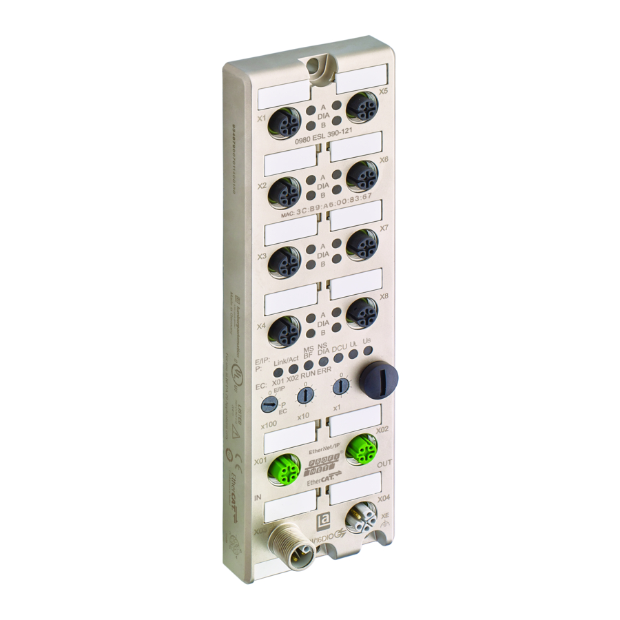
4.2 External dimensions 4 Assembly and wiring 4.2.2 Module 0980 ESL 3xx-121 Figure 2: Example figure for 0980 ESL 313-121 Manual LioN-P EtherNet/IP Version 2.0 11/2017... -
Page 21: Port Assignments
4 Assembly and wiring 4.3 Port assignments 4.3 Port assignments All the contact arrangements shown in this chapter show the frontal view of the connection area for the connectors. 4.3.1 EtherNet/IP Ports, M12 socket, 4-pin, D-coded Color coding: green Figure 3: Schematic drawing, ports X01, X02 Port Signal Function... -
Page 22: Power Supply With 7/8", 5-Pin
4.3 Port assignments 4 Assembly and wiring 4.3.2 Power supply with 7/8", 5-pin Color coding: gray Figure 4: Schematic drawing, port X03 (IN) Figure 5: Schematic drawing, port X04 (OUT) Manual LioN-P EtherNet/IP Version 2.0 11/2017... -
Page 23: Power Supply With M12 Power L-Coded
4 Assembly and wiring 4.3 Port assignments Port Signal Function Power supply X03/X04 GND_U Actuator GND_V System/sensors Function earth (+24 V) System/sensors (+24 V) Actuator Table 3: Assignment of ports X03, X04 Attention: For the input module 0980 ESL 311-xxx, the two contacts 1 and 5 are not required for the power supply to the actuators. -
Page 24: Ports For Sensors/Actuators
4.3 Port assignments 4 Assembly and wiring Figure 7: Schematic diagram of the M12 L-coded (connector), port X04 (OUT) Power supply Signal Function Power supply X03/X04 (+24 V) System/sensors GND_U Actuator GND_U System/sensors (+24 V) Actuator Function earth Table 4: Assignment of X03, X04 Attention: Only use power supply units for the system/sensor and actuator supply that correspond to PELV (protective extra low voltage) or SELV (safety extra low voltage). - Page 25 4 Assembly and wiring 4.3 Port assignments Port Pin 16DI 16DO 8DI/8DO 16DI/DO Sensor/ +24 V DC n.c. +24 V DC (ports X1..X4) +24 V DC actuator n.c. (Ports X5..X8) IN B OUT B IN B (Ports X1..X4) IN/OUT B OUT B (Ports X5..X8) 0 V DC 0 V DC 0 V DC...
-
Page 26: Configuration And Startup
5.1 EDS files 5 Configuration and startup 5 Configuration and startup The configuration and commissioning of the LioN-P EtherNet/IP modules described on the following pages was performed using an Allen-Bradley controller and the Rockwell software RSLogix 5000. If you are using a control system from another control system provider, please consult the associated documentation. -
Page 27: Reading The Mac Addresses
5 Configuration and startup 5.2 Reading the MAC addresses Install the EDS file for the module variant used with the aid of the hardware or network configuration tool of your controller manufacturer. After the installation, the modules are available in the hardware catalogs as a “General Purpose Discrete I/O”... -
Page 28: Configuration Of The Lion-P Ethernet/Ip Modules
5.4 Configuration of the LioN-P 5 Configuration and startup EtherNet/IP modules Rotary switch Function setting On delivery, the DHCP function is enabled. The network parameters are requested by DHCP requests to a server. If you want to request the network (Default setting) parameters with BOOTP requests, you must activate the BOOTP function through the web server or the TCP/IP interface object (CIP Class ID 0xF5,... - Page 29 5 Configuration and startup 5.4 Configuration of the LioN-P EtherNet/IP modules The Exclusive Owner connection type is only available for modules with an output function (variants 16DIO, 16DO and 8DI/8DO). By selecting the corresponding instance ID of the assembly object, you decide how many items of IO process data the LioN-P module makes available to the user and whether diagnostic data is to be added.
-
Page 30: 16Dio Modules: 0980 Esl 310-Xxx / 0980 Esl 390-Xxx
5.4 Configuration of the LioN-P 5 Configuration and startup EtherNet/IP modules 5.4.1.1 16DIO modules: 0980 ESL 310-xxx / 0980 ESL 390-xxx Link Connection type Diagnostics Assembly ID Length 16 DI/DO + DIA Exclusive Owner Output: 100 2 byte Input: 101 7 byte Configuration: 110 130 byte... - Page 31 5 Configuration and startup 5.4 Configuration of the LioN-P EtherNet/IP modules Link Connection type Diagnostics Assembly ID Length 8 DI/DO + DIA Input Only Output: 193 0 byte Input: 104 6 byte Configuration: 111 130 byte 8 DI/DO Input Only Output: 193 0 byte Input: 105...
- Page 32 5.4 Configuration of the LioN-P 5 Configuration and startup EtherNet/IP modules Link Connection type Diagnostics Assembly ID Length 16 DO + DIA Exclusive Owner Output: 100 2 byte Input: 106 5 byte Configuration: 114 130 byte 16 DO Exclusive Owner Output: 100 2 byte Input: 107...
- Page 33 5 Configuration and startup 5.4 Configuration of the LioN-P EtherNet/IP modules Link Connection type Diagnostics Assembly ID Length 8 DI/8 DO Input Only Output: 193 0 byte Input: 105 2 byte Configuration: 116 130 byte Table 13: 8DI/8DO profiles Link Connection type Diagnostics Assembly ID...
-
Page 34: 16Dio Dcu Modules: 0980 Esl 390-121-Dcu1
5.4 Configuration of the LioN-P 5 Configuration and startup EtherNet/IP modules Link Connection type Diagnostics Assembly ID Length Generic 16 DI + DIA Listen Only Output: 192 0 byte (Even DI/DO-bytes) Input: 108 8 byte Configuration: n/a 0 byte Table 15: Even number of DI/DO-bytes profiles 5.4.1.2 16DIO DCU modules: 0980 ESL 390-121-DCU1 Link Connection type... - Page 35 5 Configuration and startup 5.4 Configuration of the LioN-P EtherNet/IP modules Link Connection type Diagnostics Assembly ID Length 8 DI/DO + DIA + DCU Input Only Output: 193 0 byte Input: 104 24 byte Configuration: 111 130 byte 8 DI/DO + DCU Input Only Output: 193 0 byte...
- Page 36 5.4 Configuration of the LioN-P 5 Configuration and startup EtherNet/IP modules Link Connection type Diagnostics Assembly ID Length 16 DO + DIA + DCU Exclusive Owner Output: 100 20 byte Input: 106 23 byte Configuration: 114 130 byte 16 DO + DCU Exclusive Owner Output: 100 20 byte...
- Page 37 5 Configuration and startup 5.4 Configuration of the LioN-P EtherNet/IP modules Link Connection type Diagnostics Assembly ID Length 8 DI/8 DO + DCU Input Only Output: 193 0 byte Input: 105 20 byte Configuration: 116 130 byte Table 22: 8 DI/8 DO DCU profiles Link Connection type Diagnostics...
-
Page 38: 16Di Modules: 0980 Esl 311-Xxx / 0980 Esl 391-Xxx
5.4 Configuration of the LioN-P 5 Configuration and startup EtherNet/IP modules Link Connection type Diagnostics Assembly ID Length Generic 16 DI + Listen Only Output: 192 0 byte DIA + DCU Input: 108 26 byte (Even DI/DO-bytes) Configuration: n/a 0 byte Table 24: Even number of DI / DO bytes DCU profiles 5.4.1.3 16DI modules: 0980 ESL 311-xxx / 0980 ESL 391-xxx Link... -
Page 39: 8Di/8Do Modules: 0980 Esl 313-Xxx / 0980 Esl 393-Xxx / 0980 Esl 393-121-Dcu1
5 Configuration and startup 5.4 Configuration of the LioN-P EtherNet/IP modules Link Connection type Diagnostics Assembly ID Length 16-bit out + diagnostic Input Only Output: 193 0 byte Input: 101 7 byte Configuration: 105 66 byte 16-bit out Input Only Output: 193 0 byte Input: 102... -
Page 40: Configuration Parameters
5.4 Configuration of the LioN-P 5 Configuration and startup EtherNet/IP modules Link Connection type Diagnostics Assembly ID Length 8-bit in/out + diagnostic Listen Only Output: 192 0 byte Input: 101 6 byte Configuration: n/a 0 byte 8-bit in/out Listen Only Output: 192 0 byte Input: 102... - Page 41 5 Configuration and startup 5.4 Configuration of the LioN-P EtherNet/IP modules defines the monitoring procedure for the individual digital output currents for each channel. The delay time starts after a change to the output channel status. If an output is activated (rising edge) or deactivated (falling edge) the output monitoring does not start until the delay time expires.
-
Page 42: Fail Safe Configuration
5.4 Configuration of the LioN-P 5 Configuration and startup EtherNet/IP modules 5.4.2.2 Fail safe configuration These parameters are provided to all module types with digital outputs. If a breakdown/loss of EtherNet/IP communication occurs or another major fault, the outputs can be switched using parameterization into a reliable state. The following options are available: Set low (0) Disabling the output channel (digital... -
Page 43: Quickconnect Configuration
5 Configuration and startup 5.4 Configuration of the LioN-P EtherNet/IP modules Word 8 Failsafe port X1, channel A (pin 4), value range 0...2, default value 0 Word 9 Failsafe port X1, channel B (pin 2), value range 0...2, default value 0 Word 14 Failsafe port X8, channel A (pin 4), value range 0...2, default value 0 Word 15... - Page 44 5.4 Configuration of the LioN-P 5 Configuration and startup EtherNet/IP modules Attention: The prerequisite for the use of QuickConnect is the adherence to a strictly prescribed procedure. The LioN-P modules must be notified before switch-off (inhibit instruction) and switch-on (uninhibit instruction). A hard disconnect during operation is not permitted.
-
Page 45: General Settings Configuration
5 Configuration and startup 5.4 Configuration of the LioN-P EtherNet/IP modules An activation of QuickConnect does not necessarily have to be done through the configuration assembly instance. Alternatively, this can also be done at runtime with the TCP/IP interface object (CIP Class ID 0xF5, attribute 12(0x0C), value 1). - Page 46 5.4 Configuration of the LioN-P 5 Configuration and startup EtherNet/IP modules Word 0 RES DOR DCR DCL RDO RUL WIL FML Table 32: General settings on the 16DI module or 16DIO module with DI profiles Word 32 RES DOR DCR DCL RDO RUL WIL FML Table 33: General settings on the 16DO module or 16DIO module with DIO, DO and 8DI/8DO profiles Word 16...
- Page 47 5 Configuration and startup 5.4 Configuration of the LioN-P EtherNet/IP modules RDO: Report DO fault without U Diagnostic alarm message in the absence of actuator power supply (U ) and actuation of an actuator disable (0) / enable (1), default value: enable (1) DCL: DCU lock (for DCU modules only) Allow DCU function (0) / disable (1), default value: allow (0), for further details please refer to the manual for...
- Page 48 5.4 Configuration of the LioN-P 5 Configuration and startup EtherNet/IP modules 5.4.2.5 Process data direction configuration (for 16DIO modules only) These parameters are only supported by LioN-P modules for which IO mapping can be configured. Depending on the selected profile and the IO mapping, the data direction can be determined for each channel with the process data direction.
- Page 49 5 Configuration and startup 5.4 Configuration of the LioN-P EtherNet/IP modules Word 1 Process data direction port X1, channel A (pin 4), static value 1 Word 2 Process data direction port X1, channel B (pin 2), static value 1 Word 15 Process data direction port X8, channel A (pin 4), static value 1 Word 16 Process data direction port X8, channel B (pin 2), static value 1...
-
Page 50: Io Mapping Configuration (For 16Dio Modules Only)
5.4 Configuration of the LioN-P 5 Configuration and startup EtherNet/IP modules 5.4.2.6 IO mapping configuration (for 16DIO modules only) Configuration of the IO mapping makes it possible to change the data structure of the E/A data. By default each E/A channel is mapped in sequence in the process data. - Page 51 5 Configuration and startup 5.4 Configuration of the LioN-P EtherNet/IP modules Word 49 IO mapping port X1, channel A (pin 4), value range 0...7, 255, default value 0 Word 50 IO mapping port X1, channel B (pin 2), value range 0...7, 255, default value 255 Word 63 IO mapping port X8, channel A (pin 4), value range 0...7, 255, default value 7 Word 64...
-
Page 52: Configuration In Rslogix 5000
5.4 Configuration of the LioN-P 5 Configuration and startup EtherNet/IP modules Word 49 IO mapping port X1, channel A (pin 4), value range 0...7, 255, default value 0 Word 50 IO mapping port X1, channel B (pin 2), value range 0...7, 255, default value 1 Word 63 IO mapping port X8, channel A (pin 4), value range 0...7, 255, default value 6 Word 64... - Page 53 EtherNet/IP modules 7. In the open window in the upper right corner, place the Module Type Vendor Filter on Lumberg, a Belden brand. All installed LioN-P modules will be displayed. Select the desired LioN-P module and confirm with Create. 8. Give the LioN-P module a name and a valid IP address.
- Page 54 5.4 Configuration of the LioN-P 5 Configuration and startup EtherNet/IP modules 9. Select a suitable connection through Change... and confirm the entries. Further details are provided in section Connections and assembly objects on page 28. 10.The Connection tab allows you to set the cycle time, the so-called Requested Packet Interval (RPI) time.
- Page 55 5 Configuration and startup 5.4 Configuration of the LioN-P EtherNet/IP modules 11.Confirm the entries with OK. 12.In the Controller Organizer, you can view the connection data of the configuration (extension: C), the input data (extension: I), and the output data (extension: O) under the item Controller Tags through the assigned LioN-P module name and make changes accordingly.
-
Page 56: Initial Settings Of The Connection Parameters
5.4 Configuration of the LioN-P 5 Configuration and startup EtherNet/IP modules 13.Configure the LioN-P module and download the parameters to the control system. 5.4.4 Initial settings of the connection parameters Configuration tools of other controller manufacturers may ask you to enter additional parameters for setting up a communication link between your EtherNet/IP scanner and the LioN-P modules. -
Page 57: 16Dio Module With 16Di/Do Profile And Diagnostic
5 Configuration and startup 5.4 Configuration of the LioN-P EtherNet/IP modules 5.4.4.1 16DIO module with 16DI/DO profile and diagnostic Transport type Exclusive Owner Trigger mode Cyclic Requested packet interval (RPI) Minimum 1 ms Sender to target device (O > T), connection parameters Real-time transfer format 32-bit run/idle header Connection type... -
Page 58: 16Do Slot With Diagnostics
5.4 Configuration of the LioN-P 5 Configuration and startup EtherNet/IP modules Connection type POINT2POINT Assembly instance ID Data type USINT Data size 1 byte Data length 0 byte Target device to sender (T > O), connection parameters Real-time transfer format data Connection is pure data and is type USINT data size 1 byte data modeless... -
Page 59: 8Di/8Do Module With Diagnostics
5 Configuration and startup 5.4 Configuration of the LioN-P EtherNet/IP modules Sender to target device (O > T), connection parameters Real-time transfer format 32-bit run/idle header Connection type POINT2POINT Assembly instance ID Data type USINT Data size 1 byte Data length 2 byte Target device to sender (T >... - Page 60 5.4 Configuration of the LioN-P 5 Configuration and startup EtherNet/IP modules Data length 1 byte Target device to sender (T > O), connection parameters Real-time transfer format Connection is pure data and is modeless Connection type MULTICAST Assembly instance ID Data type USINT Data size...
-
Page 61: Bit Assignment Of The Process Data
6 Bit assignment of the process data 6.1 16DIO module 6 Bit assignment of the process data For the LioN-P modules, the input data are given as actual values and the output data as target values. Please note that the amount of input data is variable. The amount depends on whether the transfer of diagnostic data is to be selected. -
Page 62: Assembly Id 101 (16-Bit Input Data With Diagnostics, Default Io Mapping)
6.1 16DIO module 6 Bit assignment of the process data 6.1.2 Assembly ID 101 (16-bit input data with diagnostics, default IO mapping) Input Bit 7 Bit 6 Bit 5 Bit 4 Bit 3 Bit 2 Bit 1 Bit 0 Byte 0 X4-B X4-A X3-B... -
Page 63: Assembly Id 103 (8-Bit Output Data, Default Io Mapping, For 8Di/8Do Only)
6 Bit assignment of the process data 6.1 16DIO module 6.1.5 Assembly ID 103 (8-bit output data, default IO mapping, for 8DI/8DO only) Output Bit 7 Bit 6 Bit 5 Bit 4 Bit 3 Bit 2 Bit 1 Bit 0 Byte 0 X8-B X8-A... -
Page 64: Assembly Id 105 (8-Bit Input Data Without Diagnostics, Default Io Mapping), Not For 8Di/8Do
6.1 16DIO module 6 Bit assignment of the process data 6.1.8 Assembly ID 105 (8-bit input data without diagnostics, default IO mapping), not for 8DI/8DO Input Bit 7 Bit 6 Bit 5 Bit 4 Bit 3 Bit 2 Bit 1 Bit 0 Byte 0 X8-A... -
Page 65: Assembly Id 107 (0-Bit Input Data Without Diagnostics, Default Io Mapping)
6 Bit assignment of the process data 6.1 16DIO module 6.1.11 Assembly ID 107 (0-bit input data without diagnostics, default IO mapping) Input Bit 7 Bit 6 Bit 5 Bit 4 Bit 3 Bit 2 Bit 1 Bit 0 Byte 0 MI-IME MI-SCA MI-SCS... -
Page 66: Output Data Dcu Extension (Dcu Modules Only)
6.1 16DIO module 6 Bit assignment of the process data 6.1.14 Output data DCU extension (DCU modules only) Output Bit 7 Bit 6 Bit 5 Bit 4 Bit 3 Bit 2 Bit 1 Bit 0 Byte n 16 bit I/O DCU extension Byte n + 1 Byte n + 2 INT I/O DCU extension... -
Page 67: Input Data Dcu Extension (Dcu Modules Only)
6 Bit assignment of the process data 6.1 16DIO module 6.1.15 Input data DCU extension (DCU modules only) Input Bit 7 Bit 6 Bit 5 Bit 4 Bit 3 Bit 2 Bit 1 Bit 0 Byte n 16 bit I/O DCU extension Byte n + 1 Byte n + 2 INT I/O DCU extension... -
Page 68: 16Di Module
6.2 16DI module 6 Bit assignment of the process data 6.2 16DI module 6.2.1 Assembly ID 101 (input data with diagnostic) Input Bit 7 Bit 6 Bit 5 Bit 4 Bit 3 Bit 2 Bit 1 Bit 0 Byte 0 X4-B X4-A X3-B... -
Page 69: 16Do Module
6 Bit assignment of the process data 6.3 16DO module 6.3 16DO module 6.3.1 Assembly ID 100 (output data) Output Bit 7 Bit 6 Bit 5 Bit 4 Bit 3 Bit 2 Bit 1 Bit 0 Byte 0 X4-B X4-A X3-B X3-A X2-B... -
Page 70: Assembly Id 102 (Input Data Without Diagnostic)
6.3 16DO module 6 Bit assignment of the process data 6.3.3 Assembly ID 102 (input data without diagnostic) Input Bit 7 Bit 6 Bit 5 Bit 4 Bit 3 Bit 2 Bit 1 Bit 0 Byte 0 X4-B X4-A X3-B X3-A X2-B X2-A... -
Page 71: 8Di/8Do Module
6 Bit assignment of the process data 6.4 8DI/8DO module 6.4 8DI/8DO module 6.4.1 Assembly ID 100 (output data) Output Bit 7 Bit 6 Bit 5 Bit 4 Bit 3 Bit 2 Bit 1 Bit 0 Byte 0 X8-B X8-A X7-B X7-A X6-B... -
Page 72: Key
6.4 8DI/8DO module 6 Bit assignment of the process data 6.4.4 Key X1-A…X8-A: Status, channel A (pin 4) of slots X1 to X8 X1-B…X8-B: Status, channel B (pin 2) of slots X1 to X8 MI-LVS: Module Info Byte – undervoltage system / sensor supply MI-LVA: Module Info Byte –... -
Page 73: Diagnostics Processing
7 Diagnostics processing 7.1 Channel error 7 Diagnostics processing The modules provide advanced diagnostic behavior, in particular for the output channels to determine errors in the transmission. The firmware of the modules distinguishes between 5 different types of error. 7.1 Channel error A channel error is determined by comparing the target value set by a controller and the actual value of an output channel. -
Page 74: Voltage Errors At M12 Slots (Sensor Short Circuit)
7.2 Voltage errors at M12 slots 7 Diagnostics processing (sensor short circuit) of the module. The value of this parameter can range from 0 to 255 ms; the factory setting is 80 ms. The filter is used to avoid premature error messages when a capacitive load is activated or an inductive load is deactivated, and during other voltage peaks when a status changes. -
Page 75: Error In Actuator Power Supply
7 Diagnostics processing 7.4 Error in actuator power supply 7.4 Error in actuator power supply The voltage value at the connections for the power supply of the actuators is monitored globally and at the module level. If the actuator power supply U goes outside the voltage range of 18 to 30 V, an error is reported. -
Page 76: Integrated Web Server
8.1 Start page/status page (Status) 8 Integrated web server 8 Integrated web server The LioN-P modules are equipped with an integrated web server which makes functions available for the configuration of modules and display of status and diagnostic information. Using a standard web browser, the provided functions can be accessed via an existing TCP/IP connection. - Page 77 8 Integrated web server 8.1 Start page/status page (Status) The LioN-P modules display the channel direction, the current channel status, the IO mapping configured through the control system, and the currently displayed process data (Pr/Co) of a channel. Pressing the Calculator symbol enables the mapping values to be assigned as an overview to the input and output addresses from the controller.
- Page 78 8.1 Start page/status page (Status) 8 Integrated web server The force mode is activated by the button Switch Forcemode on. This can generally be used in offline mode (without any connection to the controller) as well as in the online mode (with connection to controller). If the status page or the web server is exited, Force Mode is automatically switched off.
- Page 79 8 Integrated web server 8.1 Start page/status page (Status) The 0 and 1 buttons in the Forcing column can be used to set physical output data for the individual channels. The X button cancels forcing for the corresponding channel. In a similar manner, the Simulation column can be used to simulate the input data of the individual channels before mapping into the process data.
-
Page 80: Configuration Page (Config)
8.2 Configuration page (Config) 8 Integrated web server 8.2 Configuration page (Config) When the Config menu item in the Web server menu bar is selected, the Configuration page opens. Network parameters such as the IP address can be configured here and the LioN-P module reset to factory settings. Executed actions must be confirmed using the Submit or Apply button. -
Page 81: System Page
8 Integrated web server 8.3 System page 8.3 System page When the System menu item in the Web server menu bar is selected, the System page opens. On this page in the Connection Status area, the current status of both Ethernet ports is displayed with regard to the connection, transfer rate and transfer mode as well as the network parameters and the PROFINET status of the LioN-P module. - Page 82 8.3 System page 8 Integrated web server Manual LioN-P EtherNet/IP Version 2.0 11/2017...
-
Page 83: Distributed Control Page (Dcu)
8 Integrated web server 8.4 Distributed control page (DCU) 8.4 Distributed control page (DCU) The Distributed Control function is an optional extension and it is only supported by LioN-P modules 0980 ESL 390-121-DCU1 and 0980 ESL 393-121-DCU1. This function enables control and monitoring tasks to be executed directly on the device using a DCU program. -
Page 84: Contact Page
8 Integrated web server 8.5 Contact page When the Contact menu item in the Web server menu bar is selected, the Contacts page opens. This provides information on the contact data for Belden Deutschland GmbH. Manual LioN-P EtherNet/IP Version 2.0 11/2017... -
Page 85: Reading The Process And Diagnostic Data
8 Integrated web server 8.6 Reading the process and diagnostic data 8.6 Reading the process and diagnostic data Request Method http GET Request URI /info.json Response format JSON Example JSON response {“name”: “0980 ESL 390-121-DCU1”,“fw-version”: “V2.1.0.2-2.0”, “hw-version”:“V1.0”, “mac”: “3C:B9:A6:00:17:00”,“bus”: 0,“failsafe”: 0, “inputs”:[3,0],“outputs”: [0,0],“consuming”: [0,0],“producing”: [0,0],“Diag”:[0,0,0,0],“dcu”: {“state”: 1,“autostart”: 0,“public”: [0,0,0,0,0,0,0,0,0,0,0,0,0,0,0,0,0,0,0,0,0,0,0,0,0,0,0,0,0,0,0,0],... - Page 86 8.6 Reading the process and 8 Integrated web server diagnostic data Fieldname Data type Description String Name of the module sysName String Firmware version fw-version String Hardware version hw-version String MAC address of the module Number 0 = Not connected to fieldbus 1 = Connected to fieldbus Number 0 = Normal output operation...
- Page 87 8 Integrated web server 8.6 Reading the process and diagnostic data Fieldname Data type Description Number[32] Contains all values of the DCU public variables DCU/public _P0 - _P31 Number[2] 16 DCU exchange bits set by PLC DCU/ consuming_bits Number[2] 16 DCU exchange bits set by DCU program DCU/ producing_bit Number[8]...
-
Page 88: Technical Data
9.1 General 9 Technical data 9 Technical data 9.1 General Protection class IP 65, IP 67, IP 69, ... (only when the connectors are screwed in or when protective caps are used) Ambient temperature -25° C to +70° C (-13° F to +158° F) Ambient humidity 98% RF (for UL applications 80% PRF) Weight... -
Page 89: Bus System
9 Technical data 9.2 Bus system 9.2 Bus system Protocol EtherNet/IP EDS files EDS-V3.21.1-LumbergAutomation-0980ESL310- xxx-yyyymmdd.eds EDS-V3.21.1-LumbergAutomation-0980ESL311- xxx-yyyymmdd.eds EDS-V3.21.1-LumbergAutomation-0980ESL312- xxx-yyyymmdd.eds EDS-V3.21.1-LumbergAutomation-0980ESL313- xxx-yyyymmdd.eds EDS-V3.21.1-LumbergAutomation-0980ESL390- xxx-yyyymmdd.eds EDS-V3.21.1-LumbergAutomation-0980ESL391- xxx-yyyymmdd.eds EDS-V3.21.1-LumbergAutomation-0980ESL392- xxx-yyyymmdd.eds EDS-V3.21.1-LumbergAutomation-0980ESL393- xxx-yyyymmdd.eds EDS-V3.21.1-LumbergAutomation-0980ESL390- xxx-DCU1-yyyymmdd.eds EDS-V3.21.1-LumbergAutomation-0980ESL393- xxx-DCU1-yyyymmdd.eds Transfer rate 100 Mbit/s, full duplex Transmission procedure 100BASE-TX Autonegotiation is supported... - Page 90 9.2 Bus system 9 Technical data Product code 31000 (0980 ESL 310-111 16DIO 7/8P SP) 31100 (0980 ESL 311-111 16DI 7/8P SP) 31200 (0980 ESL 312-111 16DO 7/8P SP) 31300 (0980 ESL 313-111 8DI8DO 7/8P SP) 31002 (0980 ESL 310-121 16DIO M12P SP) 31102 (0980 ESL 311-121 16DI M12P SP) 31202 (0980 ESL 312-121 16DO M12P SP) 31302 (0980 ESL 313-121 8DI8DO M12P SP)
-
Page 91: Power Supply For The Module Electronics/Sensors
9 Technical data 9.3 Power supply for the module electronics/sensors 9.3 Power supply for the module electronics/ sensors Nominal voltage U 24 V DC (SELV/PELV) Voltage range 18-30 V DC Power consumption of module electronics Typically 120 mA Voltage level of the sensor power supply Min. -
Page 92: Power Supply For The Actuators
9.4 Power supply for the actuators 9 Technical data 9.4 Power supply for the actuators Nominal voltage U 24 V DC (SELV/PELV) Voltage range 18-30 V DC Electric isolation Threshold value of the undervoltage detection Typ. 18 V Delay time for < 20 ms undervoltage detection Reverse polarity protection Operational indicator (U... -
Page 93: Inputs
9 Technical data 9.5 Inputs 9.5 Inputs Input connection Type 3 as per IEC 61131-2 Nominal input voltage 24 V DC Input current at 24 V DC Typically 5 mA Short-circuit protection Channel type Normally open, p-switching Number of digital channels 16 with 16DI 0 with 16DO 8 with 8DI/8DO 16 with 16DIO... -
Page 94: Outputs
9.6 Outputs 9 Technical data 9.6 Outputs Each channel can independently switch 2.0 A, the port groups X1/X2, X3/X4, X5/X6, X7/X8 can each support a total load of 6.5 A at their 4 channels. The complete port group X1…X8 can support a max. load of 9 A. Output connection Type 2.0 A as per IEC 61131-2 Nominal output current per channel:... - Page 95 9 Technical data 9.6 Outputs Attention: With inductive loads of consumption category DC13 (EN60947-5-1), the outputs can connect currents of 2.0 A at a frequency of 1 Hz. Manual LioN-P EtherNet/IP Version 2.0 11/2017...
-
Page 96: Leds
9.7 LEDs 9 Technical data 9.7 LEDs Green System/sensor power supply, voltage level 18 V <= U +/- 1 V <=30 V System/sensor power supply, voltage level < 18 V +/- 1 V or U > 30 V +/- 1 V No system/sensor power supply Green Actuator power supply, voltage level 18 V <= U +/- 1 V <=30 V Actuator power supply, voltage level... - Page 97 9 Technical data 9.7 LEDs Connected: The device has at least one connection. Green Flashing green No connection: The device has no connections. IP address exists. Duplicate IP address. The device has determined that the assigned IP address already exists. Flashing red Connection has exceeded time limit or connection interrupted.
-
Page 98: Accessories
10 Accessories 10 Accessories Information on general accessories is available on the Internet at: http://www.beldensolutions.com Manual LioN-P EtherNet/IP Version 2.0 11/2017...
Need help?
Do you have a question about the lumberg automation 0980 ESL 310 Series and is the answer not in the manual?
Questions and answers