Table of Contents
Advertisement
Quick Links
Advertisement
Table of Contents

Related Manuals for Belden Lumberg Automation 0980 ESL 308-121


Summary of Contents for Belden Lumberg Automation 0980 ESL 308-121
- Page 1 Technical manual LioN-P PROFINET IO-Link Master 0980 ESL 308-121 0980 ESL 309-121 0980 ESL 109-121 0980 ESL 109-332 0980 ESL 109-122 0980 ESL 109-331 Technical manual LioN-P PROFINET IO-Link Master Technical Support Release 2.0 04/2017 support-automation@belden.com...
- Page 2 Technical manual LioN-P PROFINET IO-Link Master Release 2.0 04/2017...
-
Page 3: Table Of Contents
Content Content About this manual General information Explanation of symbols 1.2.1 Use of danger information 1.2.2 Use of general information Version information Safety instructions Intended use Qualified personnel Designations and synonyms System description PROFINET product features I/O port features Integrated web server Other features Product overview Assembly and wiring... - Page 4 Content Starting operation GSDML file Reading the MAC addresses State on delivery Configuration of the LioN-P PROFINET I/O modules in STEP 7 6.4.1 Assigning a unique device name 6.4.2 Assigning a device name to a LioN-P module 6.4.3 Configuring the IO-Link channels 6.4.4 Parameterization of the IO-Link channels 6.4.5 Parameterization of the status/control module 6.4.6 Surveillance Timeout Configuration (LioN-P 60...
- Page 5 Content 8.6.1 For LioN-P 30 devices 8.6.2 For LioN-P 60 devices IO-Link C/Q error IO-Link device diagnostics Port Configuration Tool The integrated web server 10.1 The Status page 10.2 The Ports page 10.3 The System page 10.4 The User page Technical data 11.1 General 11.2 PROFINET protocol...
- Page 6 Content Technical manual LioN-P PROFINET IO-Link Master Release 2.0 04/2017...
-
Page 7: About This Manual
Fax +49 (0) 23 55 / 5044-333 support-automation@belden.com www.lumberg-automation.com Belden Deutschland GmbH – Lumberg Automation™ – reserves the right to make technical changes or changes to this manual at any time without notice. Technical manual LioN-P PROFINET IO-Link Master Release 2.0 04/2017... -
Page 8: Explanation Of Symbols
About this manual 1.2 Explanation of symbols Explanation of symbols 1.2.1 Use of danger information Danger information is denoted as follows: DANGER Means that death, serious physical injury or substantial damage to property will occur if the required safety measures are not taken. WARNING Means that death, serious physical injury or substantial damage to property can occur if the required safety measures are not taken. -
Page 9: Version Information
About this manual 1.3 Version information Version information Index Created Changed Changed Version number Version 1.0 Version 1.1 Version 2.0 Date 02-09-2016 06-14-2016 11-03-2016 Name/department MJ / 02RH-NT GL / 02RH-NT MJ / 02RH-NT Table 1: Overview of manual revisions Technical manual LioN-P PROFINET IO-Link Master Release 2.0 04/2017... - Page 10 About this manual 1.3 Version information Technical manual LioN-P PROFINET IO-Link Master Release 2.0 04/2017...
-
Page 11: Safety Instructions
Safety instructions 2.1 Intended use Safety instructions Intended use The devices described in this manual are decentralized input/output assemblies on a PROFINET IO network. We adhere to all safety standards when developing, producing, testing, and documenting our products. When you adhere to the handling specifications and safety instructions described for the configuration, assembly, and correct operation, there should not normally be any risks for people or equipment. -
Page 12: Qualified Personnel
Only Belden Deutschland GmbH – Lumberg Automation™ – is permitted to make changes to the hardware or software of the products that go beyond the scope of this manual. -
Page 13: Designations And Synonyms
Designations and synonyms Designations and synonyms LioN-P 30 LioN-P devices with a width of 30 mm LioN-P 60 LioN-P devices with a width of 60 mm Type A IO-Link port specification (Class A) Type B IO-Link port specification (Class B) I/O port X1 –... - Page 14 Designations and synonyms Technical manual LioN-P PROFINET IO-Link Master Release 2.0 04/2017...
-
Page 15: System Description
System description 4.1 PROFINET product features System description LioN modules (Lumberg input/output Network) function as the interface in an industrial fieldbus system: They enable a central controller on the management level to communicate with the decentralized sensors and actuators on the field level. The line or ring topologies that they can be used to create not only ensure reliable data communication but also significantly reduce the cables required and thus also the costs for installation and maintenance. - Page 16 System description 4.1 PROFINET product features PROFINET IO Device RT: The LioN-P IO-Link master modules support PROFINET IO Device RT (real-time). This allows the transmission of time sensitive process data between network components in real-time communication. PROFINET specification V2.3, Conformance Class C (CC-C): The LioN-P IO-Link master modules comply with PROFINET specification V2.3 and meet the requirements of Conformance Class C (CC-C).
-
Page 17: I/O Port Features
The master modules support the IO-Link standard v1.1. – Parametrization of the IO-Link devices in PROFINET via Siemens IO_LINK_CALL function modules for Step7 and TIA Portal. – Parametrization of the IO-Link devices via Belden IO-Link Device Tool. Usable as standalone PC-Application or callable via Siemens TIA Portal. - Page 18 System description 4.2 I/O port features 8 x IO-Link master ports: The modules have 4 type A ports with an additional hard-wired digital input on pin 2 of the I/O port. – Variants with a width of 30 mm: 4 x type B ports with electrically isolated auxiliary power supply on pins 2 and 5 of the I/O port with a total of 4 A current.
-
Page 19: Integrated Web Server
System description 4.3 Integrated web server Integrated web server Network parameter display: The integrated web server gives you the option of viewing network parameters such as the IP address, subnet mask and gateway. Displaying diagnoses: You can view the diagnoses via the integrated web server. ... -
Page 20: Product Overview
System description 4.5 Product overview Color-coded connectors: Color-coded connectors help you avoid confusion in your cabling. IP protection classes IP65/IP67/IP69k: The IP protection classes describe environmental influences that the modules can be exposed to without risk and without suffering damage, or causing a risk for the user. -
Page 21: Assembly And Wiring
Assembly and wiring 5.1 General information Assembly and wiring General information Mount the module on a flat surface using 2 screws (M4x 25/30). The torque required here is 1 Nm. Use washers for all fastening methods as per DIN 125. Note The modules have a ground connection with an M4 thread for the conduction of interference currents and the EMC immunity. -
Page 22: Outer Dimensions
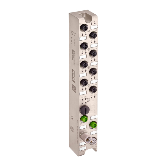
Assembly and wiring 5.2 Outer dimensions Outer dimensions 5.2.1 Module 0980 ESL 308-121 & ESL 309-121 Technical manual LioN-P PROFINET IO-Link Master Release 2.0 04/2017... -
Page 23: Module 0980 Esl
Assembly and wiring 5.2 Outer dimensions 5.2.2 Module 0980 ESL 109-121 Technical manual LioN-P PROFINET IO-Link Master Release 2.0 04/2017... - Page 24 Assembly and wiring 5.2 Outer dimensions 5.2.3 Module 0980 ESL 109-332 Technical manual LioN-P PROFINET IO-Link Master Release 2.0 04/2017...
-
Page 25: Module 0980 Esl
Assembly and wiring 5.2 Outer dimensions 5.2.4 Module 0980 ESL 109-122 Technical manual LioN-P PROFINET IO-Link Master Release 2.0 04/2017... -
Page 26: Module 0980 Esl
Assembly and wiring 5.2 Outer dimensions 5.2.5 Module 0980 ESL 109-331 Technical manual LioN-P PROFINET IO-Link Master Release 2.0 04/2017... - Page 27 Assembly and wiring 5.2 Outer dimensions Note For UL application: Be sure to use a UL-certified cable with a suitable evaluation to connect the devices (CYJV or PVVA). To program the control, please refer to the OEM information, and only use suitable accessories. Note For UL application: Only approved for interior use.
-
Page 28: Port Assignments
Assembly and wiring 5.3 Port assignments Port assignments All the contact arrangements shown in this chapter show the frontal view of the connection area for the connectors. 5.3.1 PROFINET ports, M12 socket, 4-pin, D-coded Color coding: green Figure 1: Schematic drawing, ports X01, X02 Port Signal Function... -
Page 29: Power Supply With M12 Power L-Coded
Assembly and wiring 5.3 Port assignments 5.3.2 Power supply with M12 power L-coded Color coding: gray Figure 2: Schematic diagram of the M12 L-coding (connector), port X03 (IN) Figure 3: Schematic diagram of the M12 L-coding (socket), port X04 (OUT) Power supply Signal Function... -
Page 30: Profinet And Power Supply With M12 Hybrid
Assembly and wiring 5.3 Port assignments 5.3.3 PROFINET and power supply with M12 Hybrid Color coding: gray Figure 4: Schematic diagram of the M12 Hybrid (connector) Figure 5: Schematic diagram of the M12 Hybrid (socket) Ether + Signal Function Power Supply TD +... -
Page 31: I/O Ports As M8 Or M12 Sockets
Assembly and wiring 5.3 Port assignments NOTE Only use power supply units for the system/sensor and actuator supply that correspond to PELV (Protective Extra Low Voltage) or SELV (Safety Extra Low Voltage). Power supplies according to EN 61558-2-6 (transformers) or EN 60950-1 (switching power supply units) fulfill these requirements. - Page 32 Assembly and wiring 5.3 Port assignments IO-Link Type B Color coding: black Figure 8: Schematic drawing I/O port as M8 socket IO-Link type B Figure 9: Schematic drawing I/O port as M12 socket IO-Link type B IO-Link Signal Function Type B IO-Link sensor power supply...
- Page 33 Assembly and wiring 5.3 Port assignments WARNING I/O port – Sensor supply: The sensor supply may only be carried out via the specified power connection (Power X03 --> U +24V/GND_U ) of the module. An external power supply over the I/O port (Port X1–X8 --> Pin1/Pin3) is not permitted and can lead to a destruction of the module electronics! WARNING I/O port connection (IO-Link –...
- Page 34 Assembly and wiring 5.3 Port assignments Technical manual LioN-P PROFINET IO-Link Master Release 2.0 04/2017...
-
Page 35: Starting Operation
Starting operation 6.1 GSDML file Starting operation GSDML file A GSD file in XML format is required to configure the LioN-P modules. All module variants are grouped in a single GSDML file. This can be downloaded from our homepage: http://www.beldensolutions.com/en/Service/download_center/index.phtml On request, the GSDML file is also sent by the support team. -
Page 36: State On Delivery
Starting operation 6.3 State on delivery State on delivery PROFINET parameters in state on delivery or after a factory reset: PROFINET name: Name not assigned IP address: 0.0.0.0 Subnet mask: 0.0.0.0 Device designations: 0980 ESL 109-121 0980 ESL 109-122 0980 ESL 109-331 0980 ESL 109-332 0980 ESL 308-121 0980 ESL 309-121... -
Page 37: Assigning A Device Name To A Lion-P Module
Starting operation 6.4 Configuration of the LioN-P PRO- FINET I/O modules in STEP 7 Check whether the IP address displayed is correct, and the control unit and module are on the same Ethernet subsystem. Confirm the entries by pressing "OK". 6.4.2 Assigning a device name to a LioN-P module An online PROFINET connection between the programming device and the... -
Page 38: Configuring The Io-Link Channels
Starting operation 6.4 Configuration of the LioN-P PRO- FINET I/O modules in STEP 7 6.4.3 Configuring the IO-Link channels A pre-configuration of the I/O function is automatically used for slot 1 of the subrack. By default, all channels are pre-configured as digital inputs as per the IO-Link specification. - Page 39 Starting operation 6.4 Configuration of the LioN-P PRO- FINET I/O modules in STEP 7 Right click and then select the "Clear" option in the menu that appears. First select the channel you want to delete: Figure 10: Free IO-Link channel ...
- Page 40 Starting operation 6.4 Configuration of the LioN-P PRO- FINET I/O modules in STEP 7 follows. Figure 12: Free IO-Link channel Creating an IO-Link channel configuration Click 3x on the + symbols in the hardware catalog of the device you want to configure to reveal a selection of options: Figure 13: IO-Link channel configuration Select the desired option, click and hold down the left mouse button to...
- Page 41 Starting operation 6.4 Configuration of the LioN-P PRO- FINET I/O modules in STEP 7 The following options are available for the IO-Link C/Q channel (ch. A/pin Digital Input: In this mode, the channel operates as a digital input. In this mode, the IO-Link master does not try to independently establish communication to the connected IO-Link device.
- Page 42 Starting operation 6.4 Configuration of the LioN-P PRO- FINET I/O modules in STEP 7 Digital Output: In this mode, the channel operates as a digital output. It is impossible at any time to communicate with the connected device. The “Digital Output” option for IO-Link C/Q channel (ch. A/pin4) is not available for the 0980 ESL 308-121 device.
-
Page 43: Parameterization Of The Io-Link Channels
Starting operation 6.4 Configuration of the LioN-P PRO- FINET I/O modules in STEP 7 6.4.4 Parameterization of the IO-Link channels Double-clicking on the corresponding IO-Link sub-slot in the hardware configuration and selecting the "Parameter" tab, lets you set the following parameters: Figure 14: Parameter of the IO-Link channels IOL Parameter storage... - Page 44 Starting operation 6.4 Configuration of the LioN-P PRO- FINET I/O modules in STEP 7 The following options can be set: Disabled: Disabled mode is the default setting in as-delivered condition. The data maintenance function is disabled. If parameter data of a device were stored previously, these data remain stored without any changes.
- Page 45 Starting operation 6.4 Configuration of the LioN-P PRO- FINET I/O modules in STEP 7 Upload only (device to master): Enables the parameter data upload function to the IO-Link master from the device. An upload is performed when an IO-Link device is connected and the master does not have any valid data.
- Page 46 Starting operation 6.4 Configuration of the LioN-P PRO- FINET I/O modules in STEP 7 Disabled and Cleared: The data retention function is disabled; and stored data are deleted. NOTE An IO-Link device sets the "Upload Flag" self-dependent, if parameter were written in block mode to the IO-Link device.
- Page 47 Starting operation 6.4 Configuration of the LioN-P PRO- FINET I/O modules in STEP 7 IOL Device Validation The IO-Link device validation (IO-Link device identification) lets you check the connected devices for the values set in the control program in order to, e.g., identify correctly connected devices and not start operations with them.
- Page 48 Starting operation 6.4 Configuration of the LioN-P PRO- FINET I/O modules in STEP 7 the same time. VendorID: The VendorID of the IO-Link device used can be entered as a decimal value in the "VendorID 1" (high-order byte) and "VendorID 2" (low- order byte) fields.
- Page 49 Starting operation 6.4 Configuration of the LioN-P PRO- FINET I/O modules in STEP 7 Fail Safe Configuration (for outputs only) This option is only applicable for IO-Link channels in COM mode where output data are used. In COM mode, the IO data are exchanged between the IO-Link master and IO-Link device via serial communication.
-
Page 50: Parameterization Of The Status/Control Module
Starting operation 6.4 Configuration of the LioN-P PRO- FINET I/O modules in STEP 7 – Replacement Value: If this option is selected, the value entered in the "Replacement Value" input field described below is continuously and cyclically transmitted to the IO-Link device. –... - Page 51 Starting operation 6.4 Configuration of the LioN-P PRO- FINET I/O modules in STEP 7 The status/control module in slot 1/sub-slot 1 is pre-configured for each LioN- P IO-Link master. It consists of 4 bytes of input and 4 bytes of output data for the digital IO/ data, and status and control bits of the IO-Link master.
- Page 52 Starting operation 6.4 Configuration of the LioN-P PRO- FINET I/O modules in STEP 7 The "Digital-IO Bit Mapping Mode" parameter can be used to define the mappings of the input/output bits that are transmitted in the cyclical data of the Status/Control Module from the control unit to the devices, or from the device to the control unit.
- Page 53 Starting operation 6.4 Configuration of the LioN-P PRO- FINET I/O modules in STEP 7 Diagnostics or diagnostics levels can be enabled or disabled in the General Diagnosis Settings folder. The figure shows the default setting. NOTE Report UAux supply voltage fault is disabled in the default setting, to avoid diagnostic messages due to switching the supply voltage on or off later on.
-
Page 54: Surveillance Timeout Configuration
Starting operation 6.4 Configuration of the LioN-P PRO- FINET I/O modules in STEP 7 6.4.6 Surveillance Timeout Configuration (LioN-P 60 devices) For LioN-P 60 devices, the separate power supply U , which is available on type B IO-Link channels (Ch.B / Pin2), ports 5-8, can also be configured as an additional digital output (tab: "Digital-IO mode for Ch. -
Page 55: Digital Input Logic
Starting operation 6.4 Configuration of the LioN-P PRO- FINET I/O modules in STEP 7 6.4.7 Digital input logic This parameter can be used to configure the logic of channels used as digital inputs. Figure 23: Digital input logic Default setting: NO (Normally Open) for all channels ... -
Page 56: Digital-I/O Mode For Ch. B/Pin 2
Starting operation 6.4 Configuration of the LioN-P PRO- FINET I/O modules in STEP 7 6.4.8 Digital-I/O mode for Ch. B/Pin 2 Digital-I/O mode for Ch. B/Pin 2 (LioN-P 30 devices) The type B IO-Link ports of the LioN-P 30 devices have a fixed configuration. - Page 57 Starting operation 6.4 Configuration of the LioN-P PRO- FINET I/O modules in STEP 7 Digital-I/O mode for Ch. B/Pin 2 (LioN-P 60 devices) The type B IO-Link ports, ports 5- 8 on the LioN-P 60 devices, can be parameterized as follows: Figure 25: Digital I/O mode (LioN-P 60 devices) ...
-
Page 58: Io-Link Device Parameterization
Starting operation 6.5 IO-Link device parameterization IO-Link device parameterization 6.5.1 SIEMENS IO-Link library The SIEMENS STEP 7 "IO_LINK_CALL" function module can both acyclically write device parameters of an IO-Link device and read parameters, measured values and diagnostic data. In a revised version of this library, "IO_LINK_CALL"... - Page 59 Starting operation 6.5 IO-Link device parameterization Figure 27: STEP 7 V5.5 Service data are uniquely addressed via the index and the sub-index and can be accessed or written via the logical start address of the status/control module (ID) inputs, the client access point (CAP = 255) and the corresponding IO-Link port (PORT).
-
Page 60: Snmp
Starting operation 6.6 SNMP Processing the function module always takes several PLC cycles. Calling and the use of IO-Link port functions, and non-volatile backing up or restoring of device data, must be managed by the user program. For more details, see the SIEMENS document "Acyclic reading and writing (IO-Link Library)". -
Page 61: Media Redundancy Protocol (Mrp)
Starting operation 6.7 Media Redundancy Protocol (MRP) Media Redundancy Protocol (MRP) Redundant PROFINET communication can be implemented with the LioN-P modules via a ring topology without the use of additional switches. A MRP redundancy manager terminates the ring, detects individual failures, and transmits the data packets on the redundant path in case of error. - Page 62 Starting operation 6.7 Media Redundancy Protocol (MRP) Example of setting up the MRP redundancy manager in STEP7: Example of setting up an MRP redundancy client in STEP7: Technical manual LioN-P PROFINET IO-Link Master Release 2.0 04/2017...
-
Page 63: Identification & Maintenance Functions (I&M)
Starting operation 6.8 Identification & maintenance func- tions (I&M) Example of setting up the response monitoring times in STEP7: Identification & maintenance functions (I&M) The PROFINET module has the ability to uniquely identify the devices installed in the system via an electronic nameplate. This device-specific data can be read acyclically by the user at any time. - Page 64 6.8 Identification & maintenance func- tions (I&M) Data object Length [byte] Access Default value / Description MANUFACTURER Read 0x016A (Belden Deutschland GmbH) ORDER_ID Read Order number of module in ASCII SERIAL_NUMBER 16 Read Defined in production process in ASCII HARDWARE_REV...
- Page 65 The specified index is used for mapping the data sets. Data object Length [byte] Access Default value / Description MANUFACTURER Read 0x016A (Belden Deutschland GmbH) ORDER_ID Read Order number of module SERIAL_NUMBER 16 Read Defined in production process HARDWARE_REV Read...
-
Page 66: Reading And Writing I&M Data
Starting operation 6.8 Identification & maintenance func- tions (I&M) IO-Link device I&M functions The IO-Link device-specific I&M functions 16 and 23 can be read via slot 1, sub-slot 1. The specified index is used for mapping the data sets. Only data not equal to zero are received if a connection to an IO-Link device can be established. - Page 67 Starting operation 6.8 Identification & maintenance func- tions (I&M) Data object Length [byte] Data type Coding Description I&M Data I&M 0: 54 Byte I&M Record i&M 1: 54 i&M 2: 16 i&M 3: 54 i&M 4: 54 i&M 16...23: 18 i&M 99: 13 I&M Read Record ...
- Page 68 Starting operation 6.8 Identification & maintenance func- tions (I&M) I&M Write Record I&M data can be written via the standard WRREC (SFB53) function block in STEP 7. The logical address of the slot/sub-slot (ID), the I&M index (INDEX) and the data length (LEN) must be used as handover parameters.
-
Page 69: Bit Assignment
Bit assignment 7.1 Process data Status and Control module, slot 1/sub-slot 1 Bit assignment The LioN-P PROFINET IO-Link masters use a modular device model. Slot 1 subslot 1 contains the IO-Link master status and control module. This module always has 4 bytes of input data and 4 bytes of output data; it is always statically configured on selecting a LioN-P IO-Link master from the GSD file. - Page 70 Bit assignment 7.1 Process data Status and Control module, slot 1/sub-slot 1 Byte Byte 2, IOL-COM state Port Channel 8 Table 18: Byte 2, IOL-COM state Byte Byte 3, IOL-PD valid Port Channel 8 Table 19: Byte 3, IOL-PD valid Key: ...
- Page 71 Bit assignment 7.1 Process data Status and Control module, slot 1/sub-slot 1 Byte Byte 1, Digital Output State Port Channel 8 Table 21: Byte 1, Digital Output State Byte Byte 2, COM mode Port Channel 8 Table 22: Byte 2, COM mode Byte Byte 3, reserved Port...
- Page 72 Bit assignment 7.1 Process data Status and Control module, slot 1/sub-slot 1 Output data of the Status/Control modules for 0980 ESL 308-121 Byte Byte 0, Digital Output State Port Channel - Table 24: Byte 0, Digital Output State Byte Byte 1, Digital Output State Port Channel 8...
-
Page 73: Digital Io Mapping Mode 2 (E2C Compatibility)
Bit assignment 7.1 Process data Status and Control module, slot 1/sub-slot 1 Key: Byte 0 (Pin 4, C/Q mode): The digital output on the corresponding port can be controlled via the process data. The IO-Link port must be configured as a digital output in the Engineering Tool. ... - Page 74 Bit assignment 7.1 Process data Status and Control module, slot 1/sub-slot 1 Byte Byte 3, IOL-PD valid Port Channel 8 Table 31: Byte 3, IOL-PD valid Key: The digital input data return the status of the digital inputs. The data in the cells highlighted in blue are only available for LioN-P 60 devices;...
- Page 75 Bit assignment 7.1 Process data Status and Control module, slot 1/sub-slot 1 Byte Byte 2, COM mode Port Channel 8 Table 34: Byte 2, COM mode Byte Byte 3, reserved Port Channel - Table 35: Byte 3, reserved Key: The data in the cells highlighted in blue are only available for LioN-P 60 devices.
- Page 76 Bit assignment 7.1 Process data Status and Control module, slot 1/sub-slot 1 Byte Byte 1, Digital Output State Port Channel 8 Table 37: Byte 1, Digital Output State Byte Byte 2, COM mode Port Channel 8 Table 38: Byte 2, COM mode Byte Byte 3, reserved Port...
-
Page 77: Process Data Io-Link Ports, Slot 1/Sub-Slot 2 - Sub-Slot
Bit assignment 7.2 Process data IO-Link ports, slot 1/sub-slot 2 - sub-slot 9 Process data IO-Link ports, slot 1/sub-slot 2 - sub-slot 9 The process data lengths of the IO-Link ports in COM mode depend on the IO-Link port configurations X 1 - X 8. Data lengths between 1 - 32 bytes of input data and/or 1 - 32 bytes of output data are configurable. - Page 78 Bit assignment 7.2 Process data IO-Link ports, slot 1/sub-slot 2 - sub-slot 9 Technical manual LioN-P PROFINET IO-Link Master Release 2.0 04/2017...
-
Page 79: Diagnostics Processing
Diagnostics processing 8.1 Error in the system/sensor power supply Diagnostics processing Error in the system/sensor power supply The voltage value for the incoming system/sensor power supply is also monitored globally. If the voltage drops below approx. 18,6 V, or exceeds approx. -
Page 80: Error In Auxiliary/Actuator Power Supply
Diagnostics processing 8.2 Error in auxiliary/actuator power supply Error in auxiliary/actuator power supply The voltage value for the incoming auxiliary/actuator power supply is also monitored globally. If U diagnostic messaging is enabled, an error message is generated if the voltage drops below approx. 18,6 V or exceeds approx. -
Page 81: Overload/Short Circuit Of The Digital 500 Ma Outputs
Diagnostics processing 8.4 Overload/short circuit of the digital 500 mA outputs Alternatively, the following error message is generated: Channel number of diagnosis 0x01 - 0x08 Channel related diagnosis code 0x0113 Channel related diagnosis code High temperature limit of IO-Link port driver exceeded message (short circuit or overload), detected by IO-Link master. -
Page 82: Overload/Short Circuit Of The Type B Port Aux. Power Supply
Diagnostics processing 8.6 Overload/short circuit of the type B port aux. power supply Target value Actual value Comment OK, no diagnosis Active Short-circuit Channel indicator is red. Channel error bit in the diagnosis is set. Channel is locked after the error is rectified. Table 40: Interpretation of channel errors When an output channel is activated (rising edge of the channel state) or deactivated (falling edge), the channel errors are filtered for the period that... -
Page 83: For Lion-P 60 Devices
Diagnostics processing 8.7 IO-Link C/Q error Channel number of diagnosis 0x8000 (diagnosis not channel-specific) Channel related diagnosis code 0x0108 Channel related diagnosis code Short circuit or overload of auxiliary power supply at Pin 2 message of type B I/O ports, detected by IO-Link master. 8.6.2 For LioN-P 60 devices In case of an overload or a short circuit between pin 2 and pin 5 on these... - Page 84 Diagnostics processing 8.8 IO-Link device diagnostics Standard channel diagnosis message: Channel number of diagnosis 0x01 - 0x08 Channel related diagnosis code Depends on IO-Link device diagnosis Channel related diagnosis code Depends on IO-Link device diagnosis message Extended channel diagnosis message: Channel number of diagnosis 0x01 - 0x08 Ext.
- Page 85 Diagnostics processing 8.8 IO-Link device diagnostics Value Definition Error Event Qualifier Mode: Value Definition Reserved Event single shot Event disappears Event appears Technical manual LioN-P PROFINET IO-Link Master Release 2.0 04/2017...
- Page 86 Diagnostics processing 8.8 IO-Link device diagnostics Technical manual LioN-P PROFINET IO-Link Master Release 2.0 04/2017...
-
Page 87: Port Configuration Tool
Port Configuration Tool Port Configuration Tool The Belden IO-Link Device Tool is a PC engineering software for configuring IO-Link devices via the Belden IO-Link Master. The engineering software communicates via UDP over the Ethernet interface of the IO-Link master. Therefore no additional hardware neither a running real time protocol is needed. - Page 88 Port Configuration Tool Figure 28: Port configuration tool - Main window Technical manual LioN-P PROFINET IO-Link Master Release 2.0 04/2017...
-
Page 89: 10 The Integrated Web Server
The integrated web server 10 The integrated web server The LioN-P modules are equipped with an integrated web server which makes functions available for the configuration of modules and display of status and diagnostic information. Enter http:// followed by the IP address, such as http://192.168.1.5, in your web browser’s address bar. -
Page 90: The Status Page
The integrated web server 10.1 The Status page 10.1 The Status page The status page provides a quick overview of the current state of the module. The left side shows a graphical representation of the module with all its LEDs and the positions of the rotary encoding switches. - Page 91 The integrated web server 10.1 The Status page The "Port Information" table shows the configuration and state of all the module's I/O ports. Force Mode: The force mode is a test option for the plant engineer, the input and output data can be set from this web page.
- Page 92 The integrated web server 10.1 The Status page Technical manual LioN-P PROFINET IO-Link Master Release 2.0 04/2017...
-
Page 93: The Ports Page
The integrated web server 10.2 The Ports page 10.2 The Ports page Detailed port information is shown here. "Port Diagnosis" shows incoming and outgoing diagnoses in clear text. "Pin 2" and "Pin 4" contain information about the configuration and state of the port. -
Page 94: The System Page
The integrated web server 10.3 The System page 10.3 The System page The System page shows basic information for the module. The current firmware, its version, and the firmware date can be viewed below "Firmware" as well as the version of the web interface. All the information about the module itself is located below "Device". - Page 95 The integrated web server 10.3 The System page On this page you have the option to access the following values and parameters: Restart Device: The module initializes a software reset. Reset to Factory Settings: The module restores to the default factory settings. ...
-
Page 96: The User Page
The integrated web server 10.4 The User page 10.4 The User page The User page provides the user management of the web interface. New users with access rights Admin or Write can be added here. For security reasons please change the default admin password immediately after configuring the device. -
Page 97: 11 Technical Data
Technical data 11.1 General 11 Technical data 11.1 General Protection class IP65 IP67 IP69K (This only applies if the connectors are screwed together or covers are used.) (not under UL investigation) Ambient temperature -20 °C to +70 °C (- 4 °F to +158 °F) Weight (LioN-P 30) 480g LioN-P 60... -
Page 98: Power Supply For The Module Electronics/Sensors
Technical data 11.3 Power supply for the module electronics/sensors Transmission procedure 100BASE-TX Autonegotiation is supported Vendor ID 016A DeviceID 0305 Supported Ethernet protocols Ping LLDP SNMPv1 (network diagnostics) Read Community: public Write Community: private ... -
Page 99: Power Supply Type B Ports (Auxiliary Supply)
Technical data 11.4 Power supply type B ports (auxi- liary supply) 11.4 Power supply type B ports (auxiliary supply) Rated voltage U 24 V DC (SELV/PELV) Voltage range 18-30 V DC Reverse polarity protection Operational indicator (U LED green, U >... -
Page 100: Configured As A Digital Output (Except 0980 Esl 308-121)
Technical data 11.5 IO-Link master ports (X1-X8, Ch. A/C/Q/ Pin 4) 11.5.2 Configured as a digital output (except 0980 ESL 308-121) NOTE Power is supplied to the 500 mA outputs via the U power supply. Output type Normally open, p-switching Nominal output current per channel 500 mA (for UL application 400 mA) Signal status “1”... -
Page 101: Digital Inputs (X1 - X4, Type A Ports, Ch. B/Pin 2)
Technical data 11.6 Digital inputs (X1 – X4, type A ports, ch. B/pin 2) 11.6 Digital inputs (X1 – X4, type A ports, ch. B/pin 2) Input connection Type 1 as per IEC 61131-2 Nominal input voltage 24 V DC Input current Typically 3 mA Channel type... -
Page 102: Leds
Technical data 11.8 LEDs 11.8 LEDs Green Auxiliary sensor/actuator voltage approx. >18,6 V - <30 V red* Auxiliary sensor/actuator voltage approx. <18 ,6 V or >30 V * if "Report U(Aux) supply voltage fault" is enabled. None of the above conditions Green System/sensor voltage approx. -
Page 103: 12 Accessories
Accessories 12 Accessories Item number Description 0985 706 100/… M Connection cable for Ethernet interface, assembled with M12 connector at both ends, straight, 4-pin, D-coded, 24AWG TPE with blue-green shield, highly flexible, multi-wire/unshielded, 2 twisted wire pairs. 0985 706 101/… M Connection cable for Ethernet interface, crossover, with M12 connector at both ends, straight, 4-pin, D-coded, 24AWG TPE with blue-green shield, highly flexible, multi-wire/unshielded, 2 twisted wire... - Page 104 Accessories Item number Description RKT 5L-726/... M M12 Power connection cable coupling L-coded, straight, unshielded, drag chain capable PUR RKT 5L-727/... M M12 Power connection cable coupling L-coded, straight, unshielded, drag chain capable PUR RKT 5L-738/... MRKT M12 Power connection cable coupling L-coded, straight, unshielded RKTS 5L-724/...
- Page 105 Accessories Item number Description RKCCS 5L/11 3-6 M12 Power assembly-capable coupling L-coded, straight, shielded, cable grommet 3-6 mm, connection type Crimp RKCCS 5L/11 5-9 M12 Power assembly-capable coupling L-coded, straight, shielded, cable grommet 5-9mm, connection type Crimp RKCCS 5L/11 8-11 M12 Power assembly-capable coupling L-coded, straight, shielded, cable grommet 8-11mm, connection type Crimp RKCWCS 5L/11 3-6...
Need help?
Do you have a question about the Lumberg Automation 0980 ESL 308-121 and is the answer not in the manual?
Questions and answers