Table of Contents
Advertisement
Quick Links
Advertisement
Table of Contents

Related Manuals for MKS Oriel Instruments 3502


Summary of Contents for MKS Oriel Instruments 3502
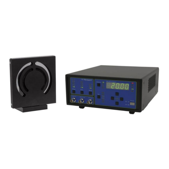
- Page 1 Model 3502, 3502-BASE Optical Chopper System User’s Manual ® Oriel Instruments MKS Newport Family of Brands – ILX Lightwave • Corion • New Focus™ • Oriel Instruments • Richardson Gratings™ • Spectra-Physics ® ® ® ® P/N: 90068136 REV: B, 8/12/2022...
-
Page 2: Table Of Contents
3502 Optical Chopper System Table of Contents Safety Precautions Definitions and Symbols ..................6 1.1.1 General Warning or Caution ............... 6 1.1.2 Electrical Shock ..................6 1.1.3 European Union CE Mark ................7 1.1.4 On ........................ 7 1.1.5 Off ....................... 7 1.1.6 Waste Electrical and Electronic Equipment (WEEE) ......... - Page 3 3502 Optical Chopper System 3.2.4 Mounting the Wheel Cover ............... 19 Initial Setup ....................... 20 3.3.1 Power ......................20 3.3.2 Connecting the Chopper Head to the Chopper Controller ......21 3.3.3 Connecting the Chopper Controller to a Computer via USB ....21 Operation ......................
- Page 4 3502 Optical Chopper System Request for Assistance / Service ............... 46 Repair Service ....................46 Non-Warranty Repair ..................47 Warranty Repair ....................47 Loaner / Demo Material ..................48...
- Page 5 3502 Optical Chopper System Figures Figure 1: Exclamation symbol................6 Figure 2: Electrical Shock symbol..............6 Figure 3: CE mark....................7 Figure 4: ON symbol..................7 Figure 5: OFF symbol..................7 Figure 6: WEEE Directive symbol..............7 Figure 7: Warning, Certification, and Information Label.
-
Page 6: Safety Precautions
3502 Optical Chopper System Safety Precautions Definitions and Symbols The following terms and symbols are used in this manual. General Warning or Caution 1.1.1 Figure 1: Exclamation symbol. The Exclamation symbol in the figure above appears in Warning and Caution tables throughout this manual. -
Page 7: European Union Ce Mark
3502 Optical Chopper System European Union CE Mark 1.1.3 Figure 3: CE mark. The presence of the CE Mark on Newport equipment means that this instrument has been designed, tested and certified compliant to all applicable European Union (CE) regulations and recommendations. 1.1.4 Figure 4: ON symbol. -
Page 8: Warnings And Cautions
3502 Optical Chopper System user can drop off WEEE waste for recycling, please contact your local Newport representative. Warnings and Cautions General Warnings 1.2.1 Observe these general warnings when operating or servicing this equipment: • Thoroughly read and understand this User’s Manual. •... - Page 9 3502 Optical Chopper System WARNING If this equipment is used in a manner not specified in this manual, the protection provided by this equipment may be impaired. WARNING This instrument is intended for use by qualified personnel who recognize thermal, shock, or laser hazards and are familiar with safety precautions required to avoid possible injury.
-
Page 10: Location Of Labels And Warnings
3502 Optical Chopper System Location of Labels and Warnings Model 3502 Optical Chopper Controller Rear Panel 1.3.1 Figure 7: Warning, Certification, and Information Label. -
Page 11: General Information
3502 Optical Chopper System General Information System Overview The Model 3502 Optical Chopper is used to introduce a periodic interruption of a light path in an optical experiment resulting in an amplitude modulation, which is useful for many small optical signal detection schemes. The modulation frequency can be controlled from 4 Hz to 10.65 kHz. -
Page 12: Unpacking And Inspection
3502 Optical Chopper System Unpacking and Inspection WARNING Do not attempt to operate this equipment if there is evidence of shipping damage or you suspect the unit is damaged. Damaged equipment may present additional hazards to you. Contact Newport technical support for advice before attempting to plug in and operate damaged equipment. -
Page 13: Environmental Operation Requirement
3502 Optical Chopper System Environmental Operation Requirement Operating Limits 2.4.1 Parameter Minimum Maximum Voltage Requirements 100V/50-60Hz 240V/50-60Hz 25 Watts Electrical Ratings 100-240 VAC 50-60 Hz 10 °C (≤ 90% humidity, non- 40 °C (≤ 90 % humidity, Operating temperature condensing) non-condensing) 0 °C (≤... -
Page 14: Using The Chopper
3502 Optical Chopper System Using the Chopper How the Model 3502 Optical Chopper Works The Model 3502 Optical Chopper is designed to interrupt light paths in optical experiments at frequencies from 4 Hz to 10.65 kHz. Both single- and dual-beam experiments can be performed across a broad range of chopping frequencies. -
Page 15: Mounting The Unit
3502 Optical Chopper System Figure 8: Functional block diagram for Model 3502 Optical Chopper. Mounting the Unit Chopper Head 3.2.1 The Model 3502 Optical Chopper Head (Figure 9 and Figure 10) may be secured to standard optical benches using ¼”-20 or M6 bolts. The bolts pass through the mounting plate perpendicular to the plane of the optical bench. -
Page 16: Figure 9: Model 3502 Optical Chopper Head With Wheel Cover Installed
3502 Optical Chopper System Figure 9: Model 3502 Optical Chopper Head with wheel cover installed. -
Page 17: Chopper Motor
3502 Optical Chopper System Figure 10: Dimensions of Model 3502 Optical Chopper Head. Dimensions in inches (mm). Chopper Motor 3.2.2 The operating life of the Chopper motor is limited. Long-term use of the motor at high speed will result in faster wear and a shorter lifetime. Contact Newport for details about the replacement part, 3502-MOTOR, if this becomes necessary. -
Page 18: Figure 11: Chopper Wheels
3502 Optical Chopper System Figure 11: Chopper wheels. Top row: 2-slot and 60/2-slot wheels. Middle row:7/5-slot and 42/30-slot wheels. Bottom row: 60-slot and 100-slot wheels. All wheels are 4.50” (114.3 mm) O.D. -
Page 19: Mounting The Wheel Cover
3502 Optical Chopper System WARNING The moving wheel may inflict injury. The operator should ensure the safety of personnel who may be exposed to this hazard. Mounting the Wheel Cover 3.2.4 WARNING The wheel cover is provided for safety and its installation is encouraged. -
Page 20: Initial Setup
3502 Optical Chopper System cover to the base with one of the 4-40 x 3/8” mounting screws. Loosely fasten the three remaining screws. Tighten the four screws after they are installed. Initial Setup WARNING The Model 3502 Optical Chopper Controller is intended for use ONLY with Newport Model 3502 Optical Chopper motor heads. -
Page 21: Connecting The Chopper Head To The Chopper Controller
3502 Optical Chopper System Connecting the Chopper Head to the Chopper Controller 3.3.2 Make sure that the power switch is in the position. Connect the Chopper Head to the Controller with the provided standard shielded Ethernet cable by plugging the smaller modular connector of the cable into the Chopper Head and the larger connector into the MOTOR input on the rear panel of the Chopper Controller. - Page 22 3502 Optical Chopper System Wheel Type Lowest Frequency Highest Frequency (slots) outer outer 200 Hz 10.65 kHz 120 Hz 6.40 kHz 42/30 84 Hz 4.48 kHz 14 Hz 746 Hz 4 Hz 213 Hz 60/2 See text See text is the chopping frequency as measured by an optical pick-up on the Model outer 3502 Optical Chopper Head.
- Page 23 3502 Optical Chopper System that these signals will therefore only be as stable as the externally-controlled chopping frequency. To change the source, press the button until the LED under the desired Sync Sync source lights. Sync Mode Button button allows the User to change the frequency that F will lock to in Mode outer...
- Page 24 3502 Optical Chopper System Synth Out The signal provided by the internal synthesizer is available on this output. F Outer The signal from the optical pick-up on the Chopper Head is available on this output as a TTL signal. Set Button button selects which instrument parameter you can modify using the cursor keys.
- Page 25 3502 Optical Chopper System Set: H and S mode the user may lock the Chopper to a harmonic of the sync frequency. is set to the harmonic of interest. Use the up arrow and down arrow keys to set to an integer value from 1 to 15. The user may lock the Chopper to a subharmonic of the sync frequency.
- Page 26 3502 Optical Chopper System UNLCK LED The red LED indicates when the Chopper is not synchronized to an internal UNLCK or external sync frequency. In addition, the LED will blink when an UNLCK external sync frequency exceeds the limits for a particular wheel. USB LED LED lights when the Chopper Controller is connected to a computer.
- Page 27 3502 Optical Chopper System OUT 1 OUT 2 outer Phase Phase Sync Mode Phase is Source Output Freq. Output Freq. Output Freq. locked locked locked to 5·(Int. F Int. F (5/7)·(Int. F Int. F Int. F Int. F sync sync sync sync sync...
-
Page 28: Back Panel Operation
3502 Optical Chopper System Back Panel Operation The back panel of 3502 Optical Chopper Controller provides the functions operation described below. Figure 13: Model 3502 Optical Chopper Controller back panel. CAUTION Do not block the rear panel of the Controller. Ensure a minimum clearance of 30”... - Page 29 3502 Optical Chopper System MOTOR socket The input marked on the rear panel is used to connect the 3502 Optical MOTOR Chopper Head to the Chopper Controller with the shielded Ethernet cable provided. USB 2.0 The USB-B input port is used in connecting the Chopper Controller to a host computer system.
-
Page 30: Computer Interfacing
3502 Optical Chopper System Computer Interfacing Introduction The Model 3502 Optical Chopper can be controlled remotely over the USB 2.0 interface either via an intuitive, Windows-based Graphical User Interface (GUI) application or via commands sent from a host PC. Before connecting the instrument to the USB interface the user should install the application included on the flash drive that accompanies the Model 3502 Optical Chopper. -
Page 31: A Quick Start: How To Use The 'New Focus Chopper Application
3502 Optical Chopper System Figure 14: Model 3502 Optical Chopper Application window. A Quick Start: How to Use the ‘New Focus Chopper 4.2.1 Application’ 1. Turn the Model 3502 Optical Chopper Controller on using the power button on the front panel of the Controller. 2. -
Page 32: Usb Communication
3502 Optical Chopper System 8. To exit the application, either close the window or select ‘ from the ‘ Exit’ File’ menu. USB Communication To control the Model 3502 Optical Chopper remotely without using the GUI application, commands can be issued directly over USB using the Newport USB library. - Page 33 3502 Optical Chopper System Measures a given frequency. FR*? , 2 = , 3 = , 4 = OUT 1 OUT 2 sync outer Sets the harmonic multiplier (1 - 15). HAR[ ]? Identification query. Returns “NEW FOCUS 3502 CHOPPER IDN? <Firmware version>...
-
Page 34: Command Description
3502 Optical Chopper System Command Description FR*? Description Frequency query. FR*? Syntax Remarks The FR* command is used to query the following frequencies associated with the key on the Chopper front panel: Measure sync , and . Data is returned in Hz. OUT 1 OUT 2 outer... - Page 35 3502 Optical Chopper System IDN? Description Identification query. IDN? Syntax Remarks Returns the following string identifying the Chopper: "NEW FOCUS 3502 CHOPPER <Firmware version> <Firmware date>, SN<Serial Number>". Example IDN? Query. NEW FOCUS Response. The firmware version is 1.16, 3502 the firmware date is 5/05/14, and the CHOPPER serial number of the unit is P0004.
- Page 36 3502 Optical Chopper System MEM? Description Store and recall instrumental set-ups. MEM? Syntax The MEM command, along with the STO and RCL commands, is used Remarks to store and recall one of the 9 instrumental set-ups. After selecting which instrument set-up number to use (1 through 9) using the STO command, MEM0 will store the current instrument set-up.
- Page 37 3502 Optical Chopper System OSC[ ]? Description Set and query the synthesizer frequency. OSC[ ]? Syntax OSC command sets and queries the internal synthesizer. In Remarks mode setting the synthesizer frequency will set the chopping Sync mode the data supplied by the OSC command frequency.
- Page 38 3502 Optical Chopper System RCL[ ]? Description Selects instrument set-up for recall. RCL[ ]? Syntax RCL command will select a formerly stored instrument set-up. Remarks The RCL? query will return the recall set-up number. The data may range between 0 and 9. Recall of set-up “0” will restore the Model 3502 Optical Chopper to factory default settings.
- Page 39 3502 Optical Chopper System STO[ ]? Description Selects instrument set-up for storage. STO[ ]? Syntax Remarks command selects the instrument set-up number in which STO? to store the current Chopper set-up. The query will return the selected instrument set up number. The data may range from 1 to 9. MEMO is used with to store the instrument set-up.
- Page 40 3502 Optical Chopper System SYN[ ]? Description Set and query the source used for synchronization. SYN[ ]? Syntax The SYN command sets and queries the frequency source used for Remarks synchronization. SYN0 SYN1 Ext+ SYN2 Ext- SYN3 SYN? Query Example SYN3 Command.
-
Page 41: Troubleshooting
3502 Optical Chopper System Troubleshooting CAUTION There are no user serviceable parts inside the Model 3502 Optical Chopper Controller or Motor Head. Work performed by persons not authorized by Newport will void the warranty. Normal Startup Operation When the Chopper Controller is properly connected to the power mains and a Chopper Head, and is turned on, the front panel LEDs will blink and the display will show before recalling the last Chopper Controller set up. - Page 42 3502 Optical Chopper System frequencies allowed for a given wheel setting. Verify that this external signal is of the correct frequency. Synchronization to an external signal is unreliable: Verify that the pulse width of the external trigger pulse is at least 1 μs long. Use an oscilloscope with a high impedance input to monitor the external signal while it is connected to the Chopper Controller.
-
Page 43: Specifications
3502 Optical Chopper System Specifications Chopping Frequency Please note that specifications are subject to change without notice. Jitter (s p-p, Min. Freq. Max. Freq. typical) Wheel Model outer outer Type Number @ Min. @ Max. Freq. Freq. 3515 100-slot 200 Hz 10.65 KHz 60-slot 3514... -
Page 44: Reference Output
3502 Optical Chopper System Reference Output TTL level square wave, may be used as free-running Sync Out oscillator when using setting. EXT+ EXT- Sync TTL-level square wave at the chopping frequency. outer TTL level pulse: OUT 1 5·F mode NORMAL outer in +/- mode outer... -
Page 45: Maintenance, Warranty, And Service
Warranty and Service CONTACTING ORIEL® INSTRUMENTS Oriel® Instruments belongs to MKS Newport Corporation's family of brands. Thanks to a steadfast commitment to quality, innovation, hard work and customer care, Newport is trusted the world over as the complete source for all photonics and laser technology and equipment. -
Page 46: Request For Assistance / Service
3502 Optical Chopper System Oriel Instruments 151 Evergreen Dr. Bozeman, MT 59715 USA Telephone: 877-835-9620 (toll-free in United States); 949-863-3144 Fax: 949-253-1680 orielPV.sales@newport.com Sales: orielPV.service@newport.com Technical assistance & Repair Service: Customers outside of the United States must contact their regional representative for all sales, technical support and service inquiries. -
Page 47: Non-Warranty Repair
3502 Optical Chopper System Return the product to Oriel Instruments, freight prepaid, clearly marked with the RMA number and it will either be repaired or replaced it at Oriel's discretion. Oriel is not responsible for damage occurring in transit. The Owner of the product bears all risk of loss or damage to the returned Products until delivery at Oriel's facility. -
Page 48: Loaner / Demo Material
3502 Optical Chopper System an RMA number. Buyer bears all risk of loss or damage to the Products until delivery at Oriel's facility. Oriel shall pay for shipment back to Buyer for Products repaired under warranty. WARRANTY PERIOD The model 3502 and 3502-BASE warranty (except consumables noted below) described here are warranted for a period of twelve (12) months from the date of shipment or 3000 hours of operation, whichever comes first. - Page 49 3502 Optical Chopper System © 2022 by Newport Corporation, Irvine, CA. All rights reserved. No part of this manual may be reproduced or copied without the prior written approval of Newport Corporation. This manual has been provided for information only and product specifications are subject to change without notice. Any change will be reflected in future printings.
Need help?
Do you have a question about the Oriel Instruments 3502 and is the answer not in the manual?
Questions and answers