Table of Contents
Advertisement
Quick Links
CIRUS
UPT-6006
User Guide
®
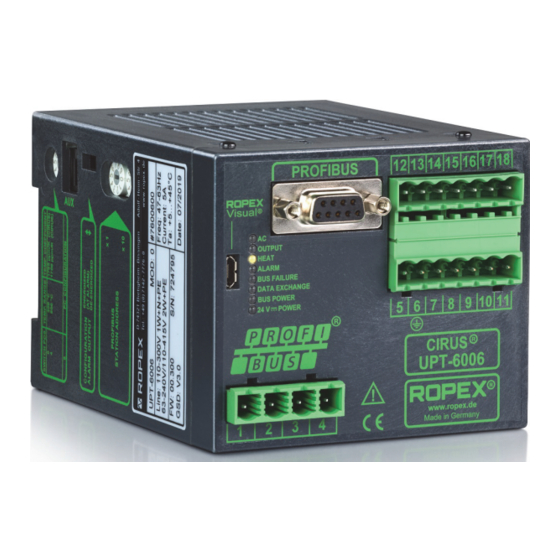
The CIRUS
temperature controller UPT-6006 is a key component in an ULTRA-PULSE system,
because it is responsible for all heat management functions, i.e. controlling the temperature of
the heating element.
Important features
•
PROFIBUS DP interface for complete regulator control
•
Automatic zeroing (AUTOCAL)
•
Automatic configuration of the secondary voltage and current range (AUTORANGE)
•
Automatic frequency adaptation
•
Booster output standard
•
Analogue output 0...10 VDC for ACTUAL temperature
•
Alarm function with error diagnosis
•
Heating element alloy and temperature range can be selected
•
Cooling system monitored
•
Wide voltage range for the use of 110...415 V
•
Eight channels for administration of various calibration values
•
Micro-USB interface for ROPEXvisual
ROPEX Industrie-Elektronik GmbH
Adolf-Heim-Str. 4
74321 Bietigheim-Bissingen (Germany)
®
Tel.: +49 (0)7142-7776-0
Fax: +49 (0)7142-7776-211
E-Mail:
info@ropex.de
Internet:
https://ropex.de
Data subject to change
Advertisement
Table of Contents

Related Manuals for Ropex CIRUS UPT-6006


Summary of Contents for Ropex CIRUS UPT-6006
- Page 1 • Wide voltage range for the use of 110…415 V • Eight channels for administration of various calibration values ® • Micro-USB interface for ROPEXvisual ROPEX Industrie-Elektronik GmbH Tel.: +49 (0)7142-7776-0 E-Mail: info@ropex.de Adolf-Heim-Str. 4 Fax: +49 (0)7142-7776-211 Internet: https://ropex.de...
-
Page 2: Table Of Contents
Contents Revision list ......3 Device functions ....19 Display and operating elements . -
Page 3: Revision List
Revision list Revision list Version Changes • Creation of documentation General information ® This CIRUS temperature controller is manufactured according to DIN EN 61010-1. In the course of its manufacture it passed through quality assurance, whereby it was subjected to extensive inspections and tests. As a result of this, the product left our factory in perfect condition. -
Page 4: Current Transformer Pex-W4/-W5
The use of an original ROPEX line filter is mandatory in order to comply with the standards and provisions mentioned in section 2.7 "Standards / CE marking" on page 4. This device must be installed and connected according to the instructions contained in section "Power supply"... -
Page 5: Maintenance
Compliance with these standards and provisions is only guaranteed if original accessories and / or peripheral components approved by ROPEX are used. If not, then the equipment is operated on the user's own responsibility. The CE marking on the controller confirms that the device itself complies with the above-mentioned standards. -
Page 6: System Description
Exact compliance with the installation and wiring instructions is essential. The system has been evolved and optimized by ROPEX GmbH in an intensive development process. Users who follow our technical recommendations will profit from the unique functionality of this technology, which reduces the customer's effort for installation, commissioning and maintenance to a minimum. -
Page 7: Device Features
Device features A highly dynamic thermoelectric control loop is established in this way because purely electrical variables are measured in rapid succession and the heating layer of the UPT heating element has a small mass. Temperature impulse Current impulses Time Thanks to the microprocessor based technology, the controller has an optimized control algorithm as well as numerous functions tailored to specific tasks such as AUTOCAL, ALARM with error diagnosis etc. -
Page 8: Mounting And Installation
5. Ensure an adequate cable cross-section for the primary and secondary circuits (Ä Application Report). 6. Use only ROPEX impulse transformers or transformers approved by ROPEX. Please note the power, duty cycle, and primary and secondary voltages (Ä Application Report). - Page 9 If one such device is not adequate for the heatsealing application, two separate overcurrent protective devices should be provided – one for the controller and one for the application ( ROPEX Application Report). The overcurrent protective device must be located directly adjacent to the controller.
-
Page 10: Power Supply
Connect core to ground. Use transformers with a one section bobbin. The power, duty cycle and voltage values must be deter- mined individually according to the application ( ROPEX SEC. Application Report and "Accessories" leaflet for impulse transformers). -
Page 11: Line Filter
ROPEX line filters are specially optimized for use in CIRUS control loops. Providing that they are installed and wired correctly, they guarantee compliance with the EMC limit values. You can find the exact specification of the line filter in the ROPEX Application Report calculated for your particular heatsealing application. - Page 12 Mounting and installation 6.5.1 PEX-W4 terminal wires terminal block Snap-on for DIN-rail 35 x 7.5 mm or 35 x 15 mm (DIN EN 50022) 6.5.2 PEX-W5 Mounting on DIN-rail 35 x 7.5 mm or 35 x 15 mm (DIN EN 50022). Page 12 UPT-6006 Version 1...
-
Page 13: Connection Diagram (Standard)
Mounting and installation Connection diagram (standard) PROFIBUS-PLUG Line filter SUB-D / 9-POLE UPT-6006 LINE (GND pwr. supply) M24 BOOSTER OUTPUT PROFIBUS DGND controller electrically (+5 V) VP isolated (+24 V pwr. supp.) P24 prim. Impulse transformer sec. 24 VDC POWER SUPPLY Heating Ground... -
Page 14: Connection Diagram With Booster Connection
Mounting and installation Connection diagram with booster connection PROFIBUS-PLUG Line filter SUB-D / 9-POLE UPT-6006 LINE Booster (GND pwr. supply) M24 PROFIBUS twisted DGND controller Max. length 1 m electrically (+5 V) VP isolated (+24 V pwr. supp.) P24 prim. Impulse transformer sec. -
Page 15: Commissioning And Operation
( see section 8.19 "Error messages" on page 49). For secondary currents I less than 30 A, the secondary high-current line must be guided 2 times (or several times) through the transformer PEX-W4 or PEX-W5 ( ROPEX application report). Version 1 UPT-6006... - Page 16 The setting of the rotary coding switch for temperature range and alloy can be overwritten by the parameter data ( section 8.7 "Parameter data" on page 31). When the switch position “9” is selected, additional temperature ranges and alloys can be set through the ROPEX ®...
-
Page 17: Heating Element
(factory setting) When the “Alarm relay contact opens with Alarm/PC CONFIGURATION” is selected, additional configurations for the behaviour of the alarm output can be set through the ROPEX visualisation software ( section 8.12 "USB ® interface for visualisation software ROPEXvisual "... -
Page 18: Commissioning Rules
(1 Hz). Then the configuration of the controller is not correct ( section 7.2 "Device configuration" on page 15, ROPEX application report). After the device configuration is correct, perform zeroing again. 10.After successful zeroing, specify a defined temperature over the PROFIBUS protocol (setpoint) and set the ST bit. -
Page 19: Device Functions
24 V POWER LED) BUS POWER Lit if internal power supply for (green PROFINET interface is OK. UPT-6006 24 V POWER Lit if external 24 VDC power www. ROPEX (green supply is present. Made in Germany Version 1 UPT-6006 Page 19... -
Page 20: Profibus Communication
The GSD files in German (.GSG) and English (.GSD or .GSE) as well as the related image files .DIB for status visualisation can be requested by e-mail (support@ropex.de) or downloaded from our homepage (https:// ropex.de). -
Page 21: Profibus Protocol
Device functions After the desired GSD file has been integrated into the design tool, one of the three communication modules (“compact”, “expanded” or “complete”) must be selected. This determines the protocol over which the UPT-6006 communicates with the PROFIBUS master. To take advantage of the controller’s complete range of functions, the right GSD version must be used. - Page 22 Device functions The 16 bit output data from the UPT-6006 to the PROFIBUS master contain the actual value or error number and status information and have the following structure: Error no., with AL = 1 Status information Actual value (compact), with AL = 0 Name: Bit no.: 8.4.2...
- Page 23 Device functions The 2x16 bit output data contain the setpoint value in the word and the error number and status information in the word : Actual value (with prefix) Name: Bit no.: Reserve Error no. Reserve Status information Name: Bit no.: 8.4.4...
- Page 24 Device functions 8.4.5 Protocol “complete” with 4-bit error number The 2x16 bit input data contain the setpoint value in the word and the control functions in the word : Reserve Setpoint value / AC temperature Name: Bit no.: ...
-
Page 25: Input Data
Device functions Reserve Channel Reserve Control function Name: Bit no.: The 4x16 bit output data contain the actual value in the word , the status information in the word , the error number in the word , and the start temperature in the word : ... - Page 26 Device functions must be entered in the input data “Setpoint/AC temperature” during activation of the AUTOCAL function (AC- Bit = 1). This specified value must remain entered until the end of the AUTOCAL function. If too high of a temperature (greater than 40 °C) or a fluctuating specification value is specified, a corresponding error message is output (error no.115 and 116;...
- Page 27 Device functions As long as the RS bit is set, no AUTOCAL and no START request are accepted. In the error diagnosis, only errors no. 5 and 7 (201…203, 901, 913) are evaluated and output. In this status, no control of the power element takes place and no measurement impulses are generated.
-
Page 28: Output Data
Device functions While the channel can be switched during performance of the AUTOCAL function, the controller works with the channel chosen at the start of the AUTOCAL function until the AUTOCAL function is completed. The channel cur- rently used by the controller is visible in the status information. 8.5.8 Setpoint Depending on the selected temperature range (... - Page 29 Time The TO bit can only be set over the parameter data in the PROFIBUS master (also over DPV1). Setting over the ROPEX visualisation software is not possible. The tolerance limits can be set up to max. ±99 K. 8.6.7 Regulation active (RA) The UPT-6006 has successfully accepted the START request and is in the control mode when RA bit = 1.
- Page 30 Device functions 8.6.9 Information active (IA) This bit is intended for later use and is currently not supported (always 0). 8.6.10 Standby active (SA) This bit is active when the RS bit is set. With it, the controller can detect when the controller has accepted the RS bit or the MP bit and the RS bit or MP bit will then be deleted again (“handshake”...
-
Page 31: Parameter Data
Device functions Parameter data The parameter data contain values for selection of the heating element alloy, the temperature range, the lower and upper tolerance band limit for temperature monitoring, the calibration temperature, the measurement impulse duration (only for special applications), as well as the optional heating time limit. They are transmitted at every system start from the PROFIBUS master to the UPT-6006. - Page 32 Device functions Function Possible values Standard value Hold mode Off, 2 sec. Calibration temperature, channel 1 20 °C -1, 0…40 °C Correction factor, channel 1 100% 25…200% 30/31 Temperature coefficient, channel 1 1700 ppm/K 400…4000 ppm/K Calibration temperature, channel 2 20 °C -1, 0…40 °C Correction factor, channel 2...
- Page 33 Device functions 8.7.1 Temperature range and alloy With this parameter, both the temperature range and the heating element alloy can be selected. By changing the standard value (10), the setting of the rotary coding switch ( section 7.2.2 "Configuration of the rotary coding switch for temperature range and alloy"...
- Page 34 Slowly increase the correction factor, starting either with the lowest value (50%) or with the value recommended in the ROPEX Application Report minus 25%, until the actual temperature at the end of the heating impulse cor- responds to the set temperature.
- Page 35 Device functions The correction factor should be checked, and if necessary corrected, whenever the machine is operated or the set temperature or the sealing time is changed. Temp. Co too large Hold value Co too small Time 8.7.11 Maximum start temperature You can set the required maximum start temperature in the parameter data (GSD file) or by means of the DPV1 protocol expansion..
- Page 36 The lower and upper tolerance band limits cannot be set through the ROPEX visualisation software. These are the same limits as with the TO bit. These can only be set through the parameter data ( section 8.7 "Parameter data"...
- Page 37 The Hold mode only affects output of the ACTUAL temperature over the PROFIBUS protocol and the numeric tem- perature display in the ROPEX visualisation software. Output of the ACTUAL temperature over the analogue output of the controller or the graphic drawing in the ROPEX visualisation software is not changed by this. Version 1...
- Page 38 Device functions The different Hold modes are depicted in the following image: ST bit ACTUAL temperature ACTUAL indication Hold off Hold on Hold Hold Hold 2 s Hold Hold End of heatsealing phase The settings for the Hold mode must be made in the parameter data ( section 8.7 "Parameter data" on page 31) or through the DPV1 protocol expansion (...
-
Page 39: Dpv1 Protocol Expansions
Device functions DPV1 protocol expansions 8.8.1 Identification and maintenance (I&M functions) The I&M functions (identification & maintenance) are helpful for identification and cataloguing of PROFIBUS devices. The UPT-6006 supports the I&M functions 0, 1, 2, 3 and 4. Access to the I&M functions is through slot 0 and is specified in IEC 61158-6-3. - Page 40 Device functions With the DPV1 protocol expansion, there is the possibility to change these settings and functions during operation of the controller. As a result, the temperature coefficient for the heating band can be adjusted through the PLC controller during the validation process, for example. The parameters of the controller can be both read and written over this acyclical service.
- Page 41 Device functions Slot Index Parameter Range of values Maximum temperature [°C] 200…500 (300) Temperature diagnosis 0: Deactivated 1: activiated Diagnosis delay [0.01 s] 0…999 (0) Heating time monitoring [0.1 s] 0…999 (0) Output 1 (temp-OK bit) 0: off 1: Active when Actual=Setpoint 2: Active when Actual=Setpoint, with latch Hold mode...
- Page 42 Device functions When writing the date or time, a plausibility check that takes leap years into account is performed. If the transferred values do not contain valid date or time information, the UPT-6006 answers with an access error 0xb7 “invalid range”.
- Page 43 Device functions In slot 1, starting with index 200, the channel-specific calibration data deviations are available ( section 8.5.6 "Master AUTOCAL (MA)" on page 27). These values can only be read but not written. Slot Index Parameter Range of values 200/201 Calibration data deviation [0.01%], channel 0 -10000…10000 (0)
-
Page 44: Undervoltage Detection
Device functions Slot Index Parameter Range of values 237/238 Initial calibration resistance [0.1 mΩ], channel 2 0…65535 (0) (0…6553.5 mΩ) 239/240 Initial calibration resistance [0.1 mΩ], channel 3 0…65535 (0) (0…6553.5 mΩ) 241/242 Initial calibration resistance [0.1 mΩ], channel 4 0…65535 (0) (0…6553.5 mΩ) 243/244... -
Page 45: Temperature Display
Device functions 8.10 Temperature display (actual value output) The UPT-6006 sends to the terminals 17+18 an analogue signal 0…10 VDC, which is proportional to the real ACTUAL temperature. UPT-6006 max. 5 mA Actual value output 0…10 VDC 0…10 VDC Temperature meter e.g. -
Page 46: Booster Connection
PROCESS CONTROL EQUIPMENT E464680 www. ROPEX Made in Germany There is a separate documentation available for the ROPEX visualisation software. The software and the docu- mentation are available in the download area (search term: “Visual”). Page 46 UPT-6006 Version 1... -
Page 47: Aux Interface
Operating hours counter The operating hours since delivery are stored in the controller. This counter works with an accuracy of 6 minutes and can only be displayed. Resetting of the counter is not possible. Display is possible with the ROPEX visualis- ®... -
Page 48: System Monitoring/Alarm Output
2…4 weeks. If the controller is switched off longer, the date and time must be set again. This can be done with the ROPEX visualisation ®... -
Page 49: Error Messages
The error messages are even more finely differentiated internally. The 3-digit error codes described below can be displayed via the PROFIBUS interface or in the ROPEX visualization software ( section 8.12 "USB interface for ®... - Page 50 Device functions Part 1 of 3: Error messages (malfunctions) NOTE: The specified error messages are output as malfunctions (actual value output emits constant error voltage; alarm LED is continuously lit; alarm relay is active). Actual value Measure if machine in Measure if initial start- Error no.
- Page 51 Device functions Part 2 of 3: Error messages (warnings) NOTE: The specified error messages are first output as warnings (actual value output switches between two values; alarm LED flashes; alarm relay is not active). After the START signal is activated, it is output as a mal- function (actual value output no longer changes, see bold-italic values;...
- Page 52 Device functions Part 3 of 3: Error messages (warnings) NOTE: The specified error messages are first output as warnings (actual value output switches between two values; alarm LED flashes; alarm relay is not active). After the START signal is activated, it is output as a mal- function (actual value output no longer changes, see bold-italic values;...
-
Page 53: Error Ranges And Causes
Device functions 8.20 Error ranges and causes Temperature controller HARDWARE Explanations of the possible error causes can be taken from the following table. Malfunc- Explanations Possible causes tion range Interruption of the load circuit after - Wire break, heating element break the U pickup point - Contacting at the heating element defective... -
Page 54: Factory Settings
Factory settings Malfunc- Explanations Possible causes tion range - Hardware error (replace controller) Internal device error/no network - Slide switch for alarm relay defective or not in correct posi- voltage tion - Network voltage missing Factory settings ® The CIRUS temperature controller UPT-6006 is configured as follows from the factory: Rotary encoder switch Heating element alloy: 1700 ppm/K... -
Page 55: Technical Data
Measurement range Secondary voltage U 0.4…120 VAC Secondary current I 30…500 A (with transformer PEX-W4/-W5) ROPEX application report PROFIBUS DP inter- Baud rates: 9.6 kbit/s; 19.2 kbit/s; 45.45 kbit/s; 93.75 kbit/s; 187.5 kbit/s; face 500 kbit/s; 1.5 kbit/s; 3 kbit/s; 6 kbit/s; 12 kbit/s... - Page 56 Besides setting through the rotary encoder switch or the PROFIBUS interface and temperature (see below), the setting for the temperature range and temperature coefficient can range be performed through the ROPEX visualisation software ( section 8.12 "USB ® interface for visualisation software ROPEXvisual " on page 46): Temperature range: 200 °C, 300 °C, 400 °C or 500 °C...
-
Page 57: Dimensions
Dimensions Dimensions 75.0 90.0 Modifications (MODs) ® The CIRUS temperature controller UPT-6006 is suitable for very many sealing applications due to its universal design. ® A device modification (MOD) is available for the CIRUS temperature controller UPT-6006 to implement special applications. -
Page 58: How To Order
50520: Continuous curr. 50 A, 520 VAC, art. no. 885509 (with UL and CSA certification) Impulse transformer For design and order specifications, see ROPEX applica- tion report Design in accordance with EN 61558 Available with UL certifications and thermal switch, if nec- essary. - Page 59 Booster B- . . . 075415: Impulse loaded 75 A, 415 VAC, art. no. 885302 100400: Impulse loaded 100 A, 400 VAC, art. no. 885304 Lines For design and order specifications, see ROPEX applica- tion report Version 1 UPT-6006 Page 59...
-
Page 60: Index
Index Index Numbers Error number format Error ranges 24 VDC power supply Expanded device diagnosis External switching amplifier AA bit AC bit Factory settings Actual value Fuse Actual value output AG bit AL bit Alarm GSD file Alarm code format Alarm output Alarm relay Heating element... - Page 61 Index PEX-W4/-W5 WA bit PEX-W5 Wiring Power loss Power supply Power supply network PROFIBUS DP interface Protocol compact, 10-bit alarm code compact, 4-bit alarm code complete, 10-bit alarm code complete, 4-bit alarm code expanded, 10-bit alarm code expanded, 4-bit alarm code RA bit Regulation active Replacing the heating element...
- Page 62 Index Page 62 UPT-6006 Version 1...
Need help?
Do you have a question about the CIRUS UPT-6006 and is the answer not in the manual?
Questions and answers