Table of Contents
Advertisement
Quick Links
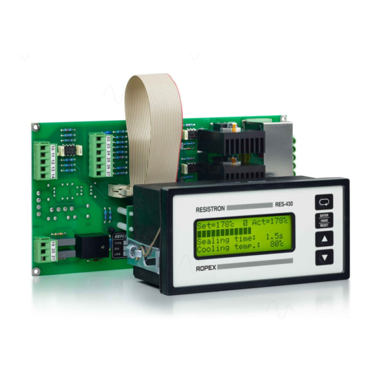
RESISTRON
RES-430
Operating
Instructions
Important features
•
Microprocessor technology
•
LC display (green), 4 lines, 20 characters (multilingual)
•
Automatic zero calibration (AUTOCAL)
•
Automatic optimization (AUTOTUNE)
•
Automatic phase angle compensation (AUTOCOMP, as of software revision 100)
•
Automatic frequency adjustment
•
Secondary control
•
Heatsealing band alloy and temperature range selectable
•
Time control, heatsealing time and cooling time settable
•
Configurable relay output, e.g. "end of cycle"
•
Time or temperature-controlled cooling phase
•
0...10VDC analog output for ACTUAL temperature
•
Load cell interface for monitoring closing pressure
•
Serial data interface (optional)
•
Fault diagnosis
ROPEX Industrie-Elektronik GmbH
Adolf-Heim-Str. 4
74321 Bietigheim-Bissingen (Germany)
Tel.: +49 (0)7142-7776-0
Fax: +49 (0)7142-7776-211
E-Mail:
info@ropex.de
Internet:
https://ropex.de
Data subject to change
Advertisement
Table of Contents

Subscribe to Our Youtube Channel
Related Manuals for Ropex RESISTRON RES-430


Summary of Contents for Ropex RESISTRON RES-430
- Page 1 • 0…10VDC analog output for ACTUAL temperature • Load cell interface for monitoring closing pressure • Serial data interface (optional) • Fault diagnosis ROPEX Industrie-Elektronik GmbH Tel.: +49 (0)7142-7776-0 E-Mail: info@ropex.de Adolf-Heim-Str. 4 Fax: +49 (0)7142-7776-211 Internet: https://ropex.de 74321 Bietigheim-Bissingen (Germany)
-
Page 2: Table Of Contents
View of the controller ... . . 20 11.1 Ropex settings ....64 General controller configuration . -
Page 3: Safety And Warning Notes
Safety and warning notes Safety and warning notes ® This RESISTRON temperature controller is manufactured according to DIN EN 61010-1. In the course of its manufacture it passed through quality assurance, whereby it was subjected to extensive inspections and tests. It left the factory in perfect condition. -
Page 4: Line Filter
Incorrect installation of the impulse transformer impairs electrical safety. Line filter The use of an original ROPEX line filter is mandatory in order to comply with the standards and provisions mentioned in section 1.5 "Standards / CE marking" on page 4. This device must be installed and connected according to the instructions contained in section 8.3, "Power supply"... -
Page 5: Application
Warranty claims must be examined in the factory and approved by ROPEX. Application This RESISTRON temperature controller is an integral part of the "series 400", the outstanding feature of which is... -
Page 6: Description Of The Controller
Description of the controller the system components, in other words the heatsealing band, the impulse transformer, the wiring, the timing sig- nals and the controller itself, are compatible with one another. We will be pleased to contribute our many years of experience your towards optimizing heatsealing system. -
Page 7: Optional Data Interfaces (Piggyback Modules)
Modifications (MODs) / optical data interface Optional data interfaces (piggyback modules) 5.2.1 Serial RS232 data interface A serial RS232 data interface (piggyback module) is optionally available for the RES-430 controller. This interface can be ordered separately and retrofitted to the motherboard. It is connected to a PC by means of a serial data cable (... - Page 8 DIAG interface for CI-USB-1 (standard as of August 2013) This data interface has a 6-pole Western socket for connecting the ROPEX communication interface CI-USB-1. As of August 2013 this data interface is installed on the motherboard of the RES-430 controller as standard. It can be retrofitted in older controllers (...
-
Page 9: Visualization Software
Modifications (MODs) / optical data interface Scope of supply / installation The data interface is supplied with spacers for installation on the motherboard of the RES-430. Proceed as follows to install it. 6-pole socket for connection of Snap-on CI-USB-1 Piggyback module Female connector, 5-pole RES-430 motherboard Male connector, 5-pole... - Page 10 Modifications (MODs) / optical data interface In addition, the software permits the values in the Configuration and Settings menus to be transferred to the con- troller or read from it. The visualization software is described in a separate document. Page 10 RES-430 Version 1...
-
Page 11: Technical Data
Technical data Technical data Type of construction RES-430 motherboard with power section: Open design for installation in the machine frame Dimensions (L x W): 210 x 110mm, height: 45mm (incl. terminals) T-430 display terminal: For installation in the machine frame Dimensions (W x H): 144 x 72mm;... - Page 12 Technical data Relay K1 Changeover contact, potential-free, U = 240VAC/100VDC, I = 1.5A Terminals 19, 20, 21 Interference suppression with 47nF / 560ohms for each terminal Solenoid drive output = 30VAC (supply voltage at terminals 17+18) (optional, instead of = 2A Terminals 15, 16, 17, Load cell interface For load cells with 2mV/V, R...
-
Page 13: Dimensions / Front Panel Cutout
Dimensions / front panel cutout Dimensions / front panel cutout Motherboard 210.0 105.0 6 x fixing hole Piggyback module Connector Specified component heights Diameter: 3.2mm (optional data for T-430 terminal for connectors, incl. interface) plug-in parts Spacing bolts with a minimum length of 6mm must be used to fasten the printed circuit board on the underside. -
Page 14: Display Terminal
Dimensions / front panel cutout Display terminal Panel cutout Outline dimensions of front frame ±0.2 ±0.2 x 68 Rubber seal Mounting clamp Connector Front frame Front panel Connecting cable (length: 250mm) Page 14 RES-430 Version 1... -
Page 15: Installation
5. Wire the system in accordance with the instructions in section 6 "Technical data" on page 11, section 8.4 "Wiring diagram with relay K1 (standard)" on page 18 and the ROPEX Application Report. The information pro- vided in section 8.2 "Installation steps" on page 15 must be heeded additionally. - Page 16 Installation • Push-on connectors on the sealing bar can lead to loose contacts. Use cables with screw connections. Page 16 RES-430 Version 1...
-
Page 17: Power Supply
LINE Line filter FILTER The filter type and size must be determined according the load, the transformer and the machine wiring ( ROPEX Application Report). Do not run the filter supply wires (line side) parallel Short to the filter output wires (load side). -
Page 18: Wiring Diagram With Relay K1 (Standard)
Wiring diagram with relay K1 (standard) GND/ Earth RES-430 LINE Main switch START Over-current protection Double-pole circuit breaker FOOT SWITCH or fuse (--> ROPEX Application report) ANALOG Short-circuit protection only. OUTPUT RES-430 controller not protected. (ACTUAL temperature of heatsealing band) +0...10VDC... -
Page 19: Wiring Diagram With Solenoid Drive (Optional)
Wiring diagram with solenoid drive (optional) GND/ RES-430 Earth LINE Main switch START Over-current protection Double-pole circuit breaker FOOT SWITCH or fuse (--> ROPEX Application report) ANALOG Short-circuit protection only. OUTPUT RES-430 controller not protected. (ACTUAL temperature of heatsealing band) +0...10VDC... -
Page 20: Startup And Operation
Startup and operation Startup and operation View of the controller 9.1.1 Motherboard Connector for terminal Terminals Connector for piggyback module (optional data interface) Terminals Nameplate 9.1.2 Front view of the terminal Connecting cables Nameplate Mounting clamps Display Operator keys Page 20 RES-430 Version 1... -
Page 21: General Controller Configuration
Startup and operation 9.1.3 Rear view of the terminal Nameplate Mounting clamps Connecting cables Mounting clamps General controller configuration The possible controller configurations are explained in the following sections. Proceed as described in section 9.7.1 "Initial startup" on page 36 to start up the controller for the first time. The menu step numbers indicated in the following are valid as of software revision 007. -
Page 22: Time Control (Timer Function)
1. Temperature coefficient 780ppm/K (e.g. Alloy L) 2. Temperature coefficient 1100ppm/K (Factory setting) (e.g. Alloy A20) 3. Temperature coefficient 1400ppm/K (e.g. ROPEX CIRUS system) 4. Temperature coefficient 1700ppm/K (e.g. ROPEX CIRUS system) 5. Temperature coefficient 3500ppm/K (e.g. LEX3500) 6. "Variable" temperature coefficient Additional settings with step 204. - Page 23 Startup and operation It is only possible to start a heating process with the "HAND" key (assuming step 213 has not been locked in the Configuration menu and the display is in the home position) on the controller. The timeout of the internal time control cannot be started with this key. START signal ACTUAL...
- Page 24 Startup and operation The current condition of relay K1 (or the optional solenoid drive) is indicated by means of a separate icon. If the icon is visible, the normally open contact of the relay is closed or the solenoid drive is active. Separate settings can be entered for the individual timeouts.
- Page 25 Startup and operation 9.3.3 Setting the heatsealing time The heatsealing time can be set in the range from 0 to 99.9s with step 104 in the Settings menu. The factory set- ting is 1.0s. START signal ACTUAL temp. = Heating phase 9.3.4 Setting the cooling mode Various criteria for the end of the cooling phase can be specified with step 210 in the Configuration menu of the...
- Page 26 Startup and operation The various cooling modes are shown below: START signal ACTUAL temp. Cooling mode = Cooling phase in Absolute = Cooling phase as Relative % of set point = Cooling phase in s Time 9.3.5 Setting the cooling value After the cooling phase has been configured with step 210 in the Configuration menu (...
- Page 27 Startup and operation of the SET temperature. This value can be set between 40 and 100%. The factory setting is 40%. 3. "Cooling time in s" (if setting with menu step 210 = "Time") The cooling phase ends when the specified time elapses. This time can be set between 0 and 99.9s. The factory setting is 10.0s.
- Page 28 Startup and operation The normally open contact of relay K1 (or the solenoid drive) closes as soon as the "START" signal is activated and remains closed until the end of the parameterized timeout (i.e. until the end of the cooling phase). 2.
-
Page 29: Temperaturediagnosis (As Of Software Revision 007)
Startup and operation The possible settings are shown below: START signal ACTUAL 95% of set point temp. End of cooling Relay K1 When start sig. present When temperature reached While cooling End-of- 500ms cycle impulse Other names are used for the settings up to software revision 006. The only possible settings are "ON, "When START signal present"... - Page 30 Startup and operation Software revision 007: The temperature diagnosis function is always active. The diagnosis begins if the ACTUAL temperature exceeds the lower tolerance limit and simultaneously corresponds to 95% of the SET temperature. The diagnosis ends at the end of the parameterized heatsealing phase. As of software revision 008: The temperature diagnosis function can be activated and deactivated with step 217 in the Configuration menu.
-
Page 31: Load Cell Interface / Temperature Sensor
Startup and operation The temperature diagnosis function can thus be explicitly deactivated during the closing movement of the sealing jaws, for instance. Error message Actual value Set+ Δϑ high Set+ Δϑ Time 9.4.1 Heatup timeout (as of software revision 100) The heatup timeout can be parameterized with step 219 in the Configuration menu ("0"... - Page 32 Startup and operation Load cell interface for force measurement active, temperature sensor not active 3. "Temperature" Temperature sensor active, load cell interface not active 4. "Temperature and force" Load cell interface for force measurement and temperature sensor active The menu steps 242 to 246 described below are accessible if step 241 is set accordingly. 9.5.2 Force diagnosis The RES-430 checks during the heatsealing phase (assuming this has been activated with step 241) whether the...
- Page 33 Startup and operation Error message Force Maximum force Minimum force Time 9.5.3 Calibration of the load cell interface / Force indication The integrated load cell must be calibrated to the specifics of each machine when the controller is started up. The necessary values can be entered with steps 244+245.
- Page 34 Startup and operation Error code Indication (if force Measured force on display diagnosis is active) Upper range limit exceeded " HHHHH " (measured value > 12.2mV) Load cell not con- " ***** " nected 9.5.4 Temperature sensor The maximum permissible temperature of the sensor can be set with step 246 (assuming the temperature sensor has been activated with step 241).
-
Page 35: Heatsealing Band
Startup and operation Heatsealing band 9.6.1 General The heatsealing band is a key component in the control loop, since it is both a heating element and a sensor. The geometry of the heatsealing band is too complex to be discussed at length here. We shall therefore only refer to a few of the most important physical and electrical properties: The measuring principle applied for this system necessitates a heatsealing band alloy with a suitable temperature coefficient TCR, i.e. - Page 36 The line frequency is automatically detected by the temperature controller in the range from 47 to 63Hz. 3. Heed the information contained in the ROPEX Application Report as well as the specifications for the heat- sealing band that is used (section 9.2 "General controller configuration" on page 21).
- Page 37 ( section 9.2 "General controller configuration" on page 21 and ROPEX Application Report). Repeat the zero point calibration after the controller has been configured correctly. 10.When the zero point has been calibrated successfully, the main menu appears on the display again. Then specify a defined temperature (heatsealing temperature) with step 101 in the Settings menu and activate the "START"...
-
Page 38: Controller Functions
Return to home position ENTER HAND RESET "ENTER" key Save values ENTER function: ROPEX HAND function: Manual mode RESET function: Reset after alarm "UP" and "DOWN" keys for setting values Press (< 2 sec.): Slow change Hold (> 2 sec.): Fast change LC display, 4 lines, multilingual 10.2... - Page 39 Controller functions 10.2.2 Display in home position If no settings are entered on the controller and no error message are present, the display is in the home position, in other words it indicates the SET temperature as a digital value and the ACTUAL temperature as a digital value and a dynamic bar.
-
Page 40: Navigation In The Menus
Controller functions 10.3 Navigation in the menus 10.3.1 Navigation in menus without an alarm A "MENU" key is provided for navigating through the various menu steps and levels. By pressing this key briefly (<1s) at any time, you can jump to the next menu step. As of software revision 100, you can also jump to the pre- vious menu step by pressing the "MENU"... - Page 41 Controller functions 10.3.2 Navigation in menus with an alarm If an alarm is signaled, the controller switches to the Alarm menu. Some faults can be acknowledged by pressing the "RESET" key ( section 10.20 "System monitoring / alarm output" on page 60). In this case, the controller switches back to the home position.
-
Page 42: Menu Structure
Controller functions 10.4 Menu structure Settings Configuration Power-up message Home position Language 1) Force sensor active 2) Force sensor not Display actual force Factory settings active 3) Time control: OFF 101 Heatsealing temp. Alloy 4) Time control: ON 5) TCR not variable 6) TCR = variable Preheating temp. - Page 43 Controller functions Configuration Continued from previous page Heatup timeout Meas. imp. length Autocomp „Output 1“ 225 Temperature unit 240 Sealing mode s/d Sensor mode 1) Force sensor or force and tem- Minimum force perature sensor active 2) Temp. sensor Maximum force active 3) No sensors active Force tare...
-
Page 44: Two-Digit Numbering System Up To Software Revision 006
Controller functions 10.5 Two-digit numbering system up to software revision 006 A system of one and two-digit numbers was used for the Settings and Configuration menus up to software revision 006. Three-digit numbers were introduced in software revision 007 to improve the clarity of the menu structure. -
Page 45: Temperature Setting (Set Point Selection)
Controller functions 10.6 Temperature setting (set point selection) The heatsealing temperature can be set by means of menu step 101. The maximum value of the setting range is limited either by the maximum value specified with step 206 in the Configuration menu or by the temperature range set with step 205. The set point that is selected for the heatsealing temperature must be greater than 40°C. - Page 46 Controller functions The relationship between the change in the output voltage and the ACTUAL temperature is linear. 0 - 300 °C range °C 20 ºC 9 10 0.66 V Voltage U “ZERO“ 0 - 500 °C range °C 20 ºC 9 10 0 4 V Voltage U...
-
Page 47: Automatic Zero Calibration (Autocal)
Controller functions 10.8 Automatic zero calibration (AUTOCAL) Owing to the automatic zero calibration (AUTOCAL) function, there is no need to adjust the zero point manually on the controller. The "AUTOCAL" function matches the controller to the current and voltage signals that are present in the system. -
Page 48: Foot Switch" Signal
Controller functions 10.9 "FOOT SWITCH" signal The "FOOT SWITCH" signal is activated by means of a control contact at terminals 12+13. max. RES-430 FOOT SWITCH with contact Activating the "FOOT SWITCH" signal energizes relay K1 (or the optional solenoid drive). Among other things, this allows the closing movement of the sealing jaws to be started. -
Page 49: Cycle Counter
Controller functions The "START" signal is activated by means of a control contact at terminals 12+14. max. RES-430 START (HEAT) with contact The "START" signal is disabled as long as the "AUTOCAL" function is executing in the Settings menu (with step 107). The set point that is selected for the heatsealing temperature (step 101 in the Settings menu) must be greater than 40°C. -
Page 50: Hold Mode
Controller functions 10.14 Hold mode The behaviour of the digital indication of the ACTUAL temperature in the home position can be changed with step 206 in the Settings menu. The following settings are possible: 1. "OFF" (Factory setting) If the main menu is visible on the display, the real ACTUAL temperature is always indicated. 2. -
Page 51: Automatic Phase Angle Compensation (Autocomp) (As Of Software Revision 100)
It may be necessary to compensate the phase angle displacement between the U and I measuring signals in certain heatsealing applications ( ROPEX Application Report). The "AUTOCOMP" function is provided for this purpose. It can be parameterized with step 221 as followed: 1. „OFF“ (Factory setting) - Page 52 Controller functions The „AUTOCOMP“ function is deactivated. 2. „ON“ The „AUTOCOMP“ function is activated by pressing the "ENTER" key after the "AUTOCAL" function has been successfully executed ( section 10.8 "Automatic zero calibration (AUTOCAL)" on page 47). The interval after the end of the "AUTOCAL"...
-
Page 53: Locking The "Hand" Key And/Or The Function „Autocal
Controller functions 3. „AUTO“ (as of software revision 101) With this setting the „AUTOCOMP“ function is activated automatically after the "AUTOCAL" function has been successfully executed. „ENTER“ key pressed „AC“ Function AUTOCOMP AUTOCAL The actual value output (terminals 10+11) is set to 0…3°C (i.e. approx. 0 VDC) when the „AUTOCAL“ and "AUTOCOMP"... - Page 54 Controller functions 4. Lock „HAND/AUTOCAL“ The "HAND" key is locked when the display is in the home position, in other words it has no function. In addition, the "AUTOCAL" function cannot be activated using step 107. Page 54 RES-430 Version 1...
-
Page 55: Temperature Unit Celsius / Fahrenheit (As Of Software Revision 102)
Controller functions 10.17 Temperature unit Celsius / Fahrenheit (as of software revision 102) As of software revision 102, the unit for the temperature indication and value selection can be switched between °C (Celsius) and °F (Fahrenheit). It can be parameterized with step 225: 1. -
Page 56: Undervoltage Detection
Controller functions 10.19 Undervoltage detection (as of software revision 007) Trouble-free operation of the temperature controller is guaranteed within the line voltage tolerance range specified in section 6 "Technical data" on page 11. If a line voltage which is less than the lower limit of the permissible range occurs, the controller is switched to a standby mode. - Page 57 Controller functions 10.19.1 Example The example below illustrates the basic design of a pneumatically operated L-sealer with a solenoid valve. The heatsealing process is started by means of a foot switch. Solenoid valve Cylinder START contact Relay K1 Sealing bar START Heatsealing band Film...
- Page 58 Controller functions The timing sequence can be represented as follows: FOOT SWITCH signal START signal ACTUAL temp. 95% of 180°C 180°C 80°C Relay K1 Closed Open Required controller settings: The following controller settings are required for time control (the basic settings such as the temperature range, alloy etc.
- Page 59 Controller functions Step in Settings menu Setting 104 (Heatsealing time) 1.0 s 105 (Cooling value) Cooling temperature = 80°C Version 1 RES-430 Page 59...
-
Page 60: System Monitoring / Alarm Output
Controller functions 10.20 System monitoring / alarm output To increase operating safety and to avoid faulty heatsealing, the controller incorporates special hardware and soft- ware features that facilitate selective fault detection and diagnosis. Both the external wiring and the internal system are monitored. - Page 61 Controller functions Version 1 RES-430 Page 61...
- Page 62 Controller functions Page 62 RES-430 Version 1...
-
Page 63: Fault Areas And Causes
- Conducting part bypasses heatsealing band completely Controller voltage measurement - Check impulse transformer specification, heed information signal outside permissible range in ROPEX Application Report Controller current measurement - Check impulse transformer specification, heed information signal outside permissible range in ROPEX Application Report ... -
Page 64: Factory Settings
Factory settings Factory settings 11.1 Ropex settings The RES-430 RESISTRON temperature controller is configured in the factory as follows (Ropex settings): Settings menu Step 101 Heatsealing temperature: 0°C Step 103 Starting delay: Step 104 Heatsealing time: Step 105 Cooling value:... -
Page 65: Customer Settings
The following settings are possible: 1. "Restore Ropex settings" (Factory setting) Selecting this option restores the menu values listed in section 11.1 "Ropex settings" on page 64. These values correspond to the factory settings with which the controller was delivered. -
Page 66: How To Order
DIAG interface as standard Line filter LF- 06480 Continuous current 6A, 480VAC, Art. No. 885500 Impulse transformer See ROPEX Application Report for design and ordering information Optional serial RS232 data interface (piggyback module) Art. No. 743099 Sub-D connecting cable for optional RS232 data interface... -
Page 67: Index
Factory settings Principle of operation Fahrenheit °F Fault areas Fault diagnosis Relay K1 "FOOT SWITCH" signal Replacing heatsealing band Force diagnosis Ropex settings Force indication Fuse Sealing time Set point selection HEAT Single/double sealing Heatsealing band type Software Heatsealing time... - Page 68 Index "START" signal Type of construction Sub-D socket System monitoring Undervoltage detection Temperature coefficient View Temperature control Visualization software Temperature diagnosis Temperature indication Temperature range Wiring Temperature sensor Wiring diagram with relay K1 Temperature setting Wiring diagram with solenoid drive Temperature unit Transformer Page 68...
Need help?
Do you have a question about the RESISTRON RES-430 and is the answer not in the manual?
Questions and answers