
Related Manuals for Ropex CIRUS UPT-6400


Summary of Contents for Ropex CIRUS UPT-6400
- Page 1 Temperature controller ® CIRUS UPT-6400 Installation and operating instructions for qualified professionals Version 1 4/17/2024...
- Page 2 Brands ® ® CIRUS and ROPEXvisual are trademarks of ROPEX Industrie-Elektronik GmbH. The following names are trademarks or registered trademarks of the respective companies: ® • QR code of DENSO WAVE INCORPORATED, Japan and/other other countries All of the trademarks stated in the instructions are the property of the respective trademark owners.
-
Page 3: Table Of Contents
Table of Contents Table of Contents Information on these operating instructions Purpose of operating instructions Target group Validity of the operating instructions Related documents 1.4.1 Related software applications Storing documentation Quality Typography Intended use Ambient conditions Safety Safety regulations How warnings are structured Symbols on the device Conformity Rules... - Page 4 Table of Contents 5.5.2 Connection diagram 5.5.3 Supply voltage Startup Note on startup Initial startup Temperature controller configuration 6.3.1 Current transformer configuration 6.3.2 Setting temperature coefficient 6.3.3 Setting temperature range Display and operating elements Switching on device Screen view 7.2.1 Standard screen 7.2.2 Adjusting screen brightness...
- Page 5 Table of Contents 8.5.3 Hold mode Timer function 8.6.1 Activation 8.6.2 Setting start delay 8.6.3 Setting sealing time 8.6.4 Setting cooling mode 8.6.5 Setting cooling value 8.6.6 Setting beginning time of sealing 8.6.7 Example Recipes 8.7.1 Recipe control 8.7.2 Blocking configuration menu Functions for special applications 8.8.1 Correction factor...
-
Page 6: Information On These Operating Instructions
„ Ensure that all information and functions that the user may require are readily available. 1.6 Quality For quality assurance purposes, the device is repeatedly inspected over the course of manufacturing. This ensures that the device leaves ROPEX in perfect condition. ® Page 6 of 104 CIRUS... -
Page 7: Typography
Information on these operating instructions | 1 1.7 Typography These instructions apply the following typography rules: Text Product name and designation Example: UPT-6400 References to other documents Example: Refer to the Application report for more information. "Text" Composite terms and references to illustrations Examples: Position "0", thermal pre-treatment of heating element "burned in"... -
Page 8: Intended Use
2 | Intended use 2 Intended use The device has been designed and tested in accordance with the latest state of tech- nology. To prevent personal injury as well as damage to equipment, use the device properly and only as intended. The temperature controller regulates the temperature of heating elements used to seal and cut thermoplastic films. -
Page 9: Safety
Safety | 3 3 Safety 3.1 Safety regulations Always read the safety regulations carefully before using the device! Install device Installation, startup and work on the device may be carried out only by qualified pro- fessionals. The persons must be familiar with the inherent dangers and warranty con- ditions. -
Page 10: Symbols On The Device
3 | Safety Signal Definition CAUTION Possible risk of minor injury, if the hazard cannot be averted. NOTE Property damage or malfunction, if the hazard cannot be averted. Meaning of symbols Symbol Definition General indication of hazard Danger, high voltage Fire hazard Note indicating potential property damage 3.3 Symbols on the device... -
Page 11: Obligation Of User
Safety | 3 Standards • DIN 46228 End sleeves • IEC 61010:2010 A1:2016 Safety requirements for electrical equipment for mea- surement, control, and laboratory use - Part 1: General requirements • DIN EN 55011/VDE 0875-11 Industrial, scientific and medical equipment - Radio- frequency disturbance characteristics - Limits and methods of measurement •... -
Page 12: Description Of Project
4 | Description of project 4 Description of project 4.1 Functioning ® The temperature controller CIRUS UPT-6400 works in the control loop like this: The resistance of the heating element changes along with the temperature of the heat- ing element. The resistance of the heating element is determined by measuring the current and voltage. -
Page 13: Overview
Description of project | 4 A timer integrated into the temperature controller allows the complete sealing process of simple machines such as tabletop sealing devices to be controlled. Three config- urable switch outputs can be used to trigger motors, magnets, etc. The process data is shown on a color screen. -
Page 14: Id Plate
4 | Description of project 40 39 38 37 36 35 34 33 24 23 22 21 20 19 ropex-group.com Made in Germany 18 17 16 15 14 13 12 ROPEX ® visual 1 Terminals 2 AUX interface 3 USB interface 4.4.1 ID plate... -
Page 15: Essential System Components
Description of project | 4 4.5 Essential system components 4.5.1 Control loop components Illustration 2: Control loop components (diagram) Pos. Component Other notes and requirements Current transformer Refer to section Current transformer [} 17] Measurement cable, current I Temperature controller Power supply Line filter Refer to section Line filters [} 17] Pulse transformer... -
Page 16: Heating Element
4 | Description of project Note The application report is needed to position and determine the essential components. 4.5.2 Heating element DANGER Fire hazard due to overheating of heating element A defect in the control loop can cause the heating element to overheat and compo- nents to catch fire. -
Page 17: Current Transformer
CE conformity of the temperature controller can only be achieved with the line filters recommended and supplied by ROPEX. The line filters damp the reaction of the phase-angle control on the line and protect the temperature controller against line dis- turbances. -
Page 18: Measurement Cable
„ Comply with the application report. 4.5.6 Measurement cable Use a twisted measurement cable supplied by ROPEX (UML-1 or UML-2). Connect the measurement cable directly to the clamping head on the sealing bar. The measurement cables UML-1 and UML-2 are twisted cables used for voltage mea- ®... -
Page 19: Assembly And Installation
Assembly and installation | 5 5 Assembly and installation 5.1 Transporting and checking device To prevent damage, always transport and store the device in the original box. After transporting the device, visually inspect the device for any damage. 5.2 Scope of delivery Check the delivery for damage and verify that it is complete. -
Page 20: Mounting Temperature Controller In Cut-Out In Control Panel
5 | Assembly and installation 5.4.1 Mounting temperature controller in cut-out in control panel ±0,2 Illustration 3: Dimensions of cut-out in control panel Prerequisite ü Line voltage is switched off and secured to prevent it from being switched on again. 1. Verify that the circuit is de-energized. 2. -
Page 21: Installation Of Device
Assembly and installation | 5 5.5 Installation of device DANGER Risk of death by electric shock There is dangerous voltage at the electrical connections to the temperature controller, the system components and the heat-sealing bar. „ Electrical installation may be performed only by qualified electricians. „... -
Page 22: Power Supply
Refer to section Current transformer [} 17] and to the application re- port. Measurement cable U NOTICE! Use twisted measuring cables provided by ROPEX. NOTICE! Input voltage max. 120 V. Refer to section Measurement cable [} 18] and to the application re- port. -
Page 23: Connection Diagram
Assembly and installation | 5 Pos. Component Notes and requirements Measurement cable, current NOTICE! Use twisted measuring cables provided by ROPEX. Refer to section Measurement cable [} 18] and to the application re- port. Filtered lines Refer to the application report. (lines between line filter and... - Page 24 5 | Assembly and installation Connection diagram for system without booster NETZ I> I> prim. sec. Heating element Pulse (EMER- transformer GENCY) Current transformer twist Line filter Temperature controller OUTPUT ANALOG IN DETACH AUTOCAL RESET 24 23 22 21 20 19 ALARM Uref START ANALOG...
- Page 25 Assembly and installation | 5 Connection diagram for system with booster NOTICE Electromagnetic compatibility disruption as a result of cables that are too long If the lines to the external booster are too long or the wires are not twisted, errors can occur when triggering the pulse transformer.
-
Page 26: Supply Voltage
5 | Assembly and installation 5.5.3 Supply voltage NOTICE Property damage caused by incorrect line voltage Incorrect line voltage can cause faulty sealing. „ Use an external voltage monitoring device Prerequisite Trouble-free operation of the temperature controller is guaranteed within the line volt- age and tolerance range specified in section Technical data. -
Page 27: Startup
Malfunctioning due to use of devices from other manufacturers Devices from other manufacturers can lead to malfunctions in the control loop. „ Use only original ROPEX accessories. „ Use only system components manufactured by ROPEX or that are approved for use with ROPEX equipment. 6.2 Initial startup... -
Page 28: Temperature Controller Configuration
6 | Startup Setting Menu number Language 201 (Operation menu) Reset to defaults 202 (Operation menu) Temperature range and temperature 301, 302, 305 (Heating element menu) coefficient of the heating element 3. If the heating element is cold, activate the AUTOCAL feature: - Via the Settings menu, menu number 107 or - via the AUTOCAL signal, terminals 34+39 ð... -
Page 29: Current Transformer Configuration
The following temperatures are possible: Temperature Note 200 °C – 300 °C Default 400 °C Only after consulting ROPEX The service- able life of the heating elements falls 500 °C drastically when operating at high sealing temperatures. ® VERSION 1 | EN-US CIRUS UPT-6400... -
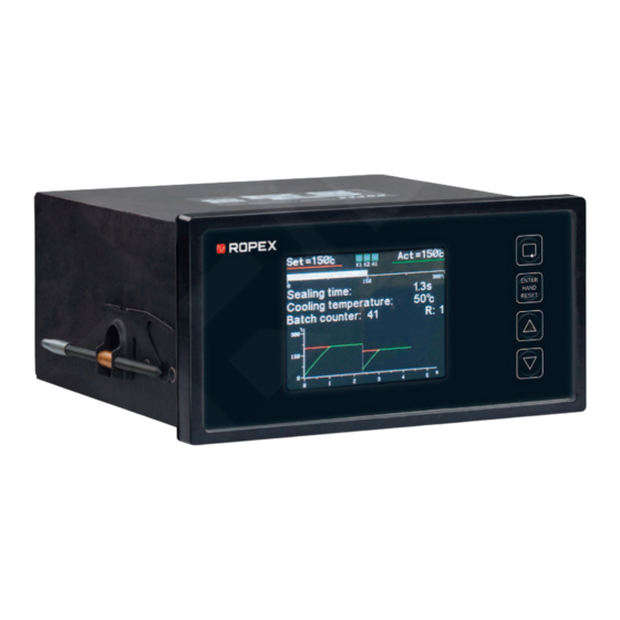
Page 30: Display And Operating Elements
7 | Display and operating elements 7 Display and operating elements Illustration 7: Display and operating elements 1 Button Menu 2 Button Enter 3 Buttons Up and Down 4 Screen Operation via screen Operate the temperature controller as follows: Button Meaning Press <... -
Page 31: Screen View
Display and operating elements | 7 5 Software ID number The switchon message is displayed for approx. 2 sec after the temperature controller is switched on. The screen also provides information on the software version. 7.2 Screen view 7.2.1 Standard screen If no settings are made to the temperature controller and there are no error messages, the screen remains in the standard view. - Page 32 2 Error code 3 Cause of error 4 Indication that Reset has to be pressed. 5 QR code with link to ROPEX web- 6 URL with link to ROPEX website, site, where more information on where more information on how to...
-
Page 33: Functions And Settings
Functions and settings | 8 8 Functions and settings 8.1 Settings 8.1.1 Settings menu / configuration menu Parameters are set at multiple menu levels: • Settings menu (operating menu; menu numbers 1xx): To access the Settings menu, press the Menu button for < 1 sec. •... - Page 34 8 | Functions and settings Menu Menu Available Description Setting range num- item only when the timer is activated (menu number 401) Standard The set setpoint and the current actual value are shown content numerically. The actual value is also indicated by the progress bar.
- Page 35 Functions and settings | 8 Menu Menu Available Description Setting range num- item only when the timer is activated (menu number 401) AUTO- This function adjusts the temperature controller to the 0 … 40 °C current and voltage signals present in the system. Press Up and Down to set the desired calibration temper- ature.
- Page 36 8 | Functions and settings 8.1.1.2 Configuration In the Configuration menu, briefly press Menu to advance to the next menu item. Press Menu for > 2 sec to access the Configuration menu. The various functions that are available is a factor of whether the timer is activated on ®...
- Page 37 Functions and settings | 8 Menu Menu Available Description Setting range num- item only when the timer is activated (menu number 401) • Start heating MAN- Specify the function of the Manual button in the standard UAL but- screen: • Start sealing cy- •...
- Page 38 8 | Functions and settings Heating element menu Menu Menu Available Description Setting range num- item only when the timer is activated (menu number 401) • TCR 1700 ppm Temper- The temperature coefficient can be set to be 1700 ppm or ature co- to be variable.
- Page 39 Functions and settings | 8 Menu Menu Available Description Setting range num- item only when the timer is activated (menu number 401) Number Number of conductors through the current transformer. In 1…9 this menu number, enter the number of times that the passes secondary current line should pass through the current through...
- Page 40 8 | Functions and settings Menu Menu Available Description Setting range num- item only when the timer is activated (menu number 401) • When heater is Begin- Specify here whether the sealing time (menu number started ning of 104) begins directly when the start signal is applied or not sealing until 95 % of the setpoint is reached.
- Page 41 Functions and settings | 8 Menu Menu Available Description Setting range num- item only when the timer is activated (menu number 401) Relay K1 Configure how relay K1 (terminals 19, 20, 21) switches Without timer: • Active when Tact = Tset Refer to section Outputs relay K1, relay K2 and output A1 for further information.
- Page 42 8 | Functions and settings Menu Menu Available Description Setting range num- item only when the timer is activated (menu number 401) Relay K2 Configure how relay K2 (terminals 22, 23, 24) switches Without timer: • Active when Tact = Tset Refer to section Outputs relay K1, relay K2 and output A1 for further information.
- Page 43 Functions and settings | 8 Menu Menu Available Description Setting range num- item only when the timer is activated (menu number 401) Output Configure how output A1 (terminals 37+38) switches on. Without timer: • Active when Tact Refer to section Outputs relay K1, relay K2 and output A1 = Tset for further information.
- Page 44 8 | Functions and settings Menu Menu Available Description Setting range num- item only when the timer is activated (menu number 401) • External alarm Function How input 1 (CH1) (terminals 39+40) functions can be set of input 1 here. •...
- Page 45 Functions and settings | 8 Menu Menu Available Description Setting range num- item only when the timer is activated (menu number 401) Setpoint If the actual value is lower than the switching threshold +3…+99 K specified here and higher that the switching threshold set ceeded in menu number 501, output A1, relay K1 and/or relay K2 can be activated if configured accordingly (menu num-...
- Page 46 8 | Functions and settings Menu Menu Available Description Setting range num- item only when the timer is activated (menu number 401) Maxi- Maximum diagnosis temperature (from one of the analog -99…999 °C mum di- sources, determined by menu number 508). If the tem- agnosis perature exceeds the threshold, error code 828 appears.
-
Page 47: Menu Navigation Without Alarm
Functions and settings | 8 Menu Menu Available Description Setting range num- item only when the timer is activated (menu number 401) Display The following events are entered into the protocol: of proto- • Alarms col en- • Execution of AUTOCAL and MASTER-AUTOCAL tries •... -
Page 48: Menu Navigation In The Event Of An Alarm
8 | Functions and settings Return to standard The system returns to the standard screen if no button is pressed for 30 sec. This screen does not apply when the temperature controller is in AUTOCAL or ALARM position. Settings Configuration Standard screen Operation Language >2 s... -
Page 49: Default
Functions and settings | 8 2. Press Enter ð The AUTOCAL function starts. Move to the configuration level To change the configuration level, proceed as follows: 1. Press Menu in the Alarm menu for longer than 2 sec. ð The temperature controller changes to the configuration level 2. - Page 50 8 | Functions and settings Menu Menu number Menu item Setting Setting Cooling tempera- Absolute cooling ture / cooling time temperature: 50 °C Relative cooling temperature: 40 % cooling time: 1.00 sec AUTOCAL tempera- 20 °C ture Correction factor 100 % Counter Load recipe Temperature of re- 0 °C lease pulse Release pulse delay 0.00 sec...
- Page 51 Functions and settings | 8 Menu Menu number Menu item Setting Heating element Number of passes through current transformer. Source of AUTO- Internal CAL temperature Machine Timer function Cooling mode Absolute Start delay 0 sec Beginning of sealing When heater is time started Alarm relay...
-
Page 52: Basic Functions
8 | Functions and settings Menu Menu number Menu item Setting Information Cycle counter (cali- For all channels: 0 bration channel) Date and time ID plate Protocol entries The parameters saved in the recipes contain the same standard values as the respec- tive single parameters. -
Page 53: Temperature Setting (Specified Setpoint)
Functions and settings | 8 8.2.2 Temperature setting (specified setpoint) There are three ways to set the sealing temperature: • In menu number 101 • By applying voltage of 0 … 10 VDC to the analog input, terminals 36+39 • By connecting a 2-kΩ potentiometer (e.g. PD-3) to the terminals 5, 18, 36 Applying voltage to the analog input, Temperature controller... -
Page 54: Automatic Zero Calibration Autocal (Ac)
8 | Functions and settings • The analog input is configured as the source of the diagnosis temperature (menu number 508). In these cases the sealing temperature is set in the Settings menu, menu num- ber 101. 8.2.3 Automatic zero calibration AUTOCAL (AC) NOTICE Property damage if the heating element overheats When the function AUTOCAL is performed while the heating element is warm, zero... -
Page 55: Configuring Alarm Relay
Functions and settings | 8 When the variable base temperature is specified via an external input, the external voltage must be activated at least 200 ms before AUTOCAL is performed. Otherwise the base temperature will not achieve the desired value. If the specified temperature is too high (greater than 40 °C) or if the specified value fluctuates, an error message appears (error code s115 and 116,;... - Page 56 8 | Functions and settings Setting Description Timer switched off (deactivated) When the START signal is activated, the device’s internal set/actual comparison is enabled. The heating element is heated to the setpoint tempera- ture. This continues until the signal is switched off. Unrelated to the START signal, this process can be triggered by pressing Manual when the stan- dard screen is shown in the display.
-
Page 57: Inputs And Outputs
Functions and settings | 8 Start request is not A start request is not processed if any of the following conditions occur: processed • The AUTOCAL function is active. • The temperature controller indicates a fault. • The setpoint is lower than 40 °C. •... -
Page 58: Restart Delay After Reset
8 | Functions and settings 8-30 VDC Temperature controller RESET max. 6 mA HIGH: ≥ 8 VDC RESET LOW: ≤ 2 VDC > 0.1 s Illustration 15: Reset signal The RESET input (terminal 33) can be connected to output U (terminal 5) via an ex- ternal button. - Page 59 0...10 VDC 0...10 VDC Temperature display °C ROPEX Voltage values • 0 VDC: 0 °C • 10 VDC: 300 °C or 500 °C (depending on device configuration) The correlation between the change in the output voltage and the actual temperature is linear.
-
Page 60: Outputs Relay K1, Relay K2 And Output A1
8 | Functions and settings Analog output Various information can be output at the analog output (terminals 17+18). The temper- ature controller is configured in the Machine menu, menu number 406. The following functions can be adjusted: Setting Description Actual temperature (default) The analog output indicates the current actual value at output voltage of 0...10 VDC. - Page 61 Functions and settings | 8 Setting Description Active when Tact = Tset The output is switched on when the ac- tual value is within the temperature toler- Actual value Set + ∆ϑ high ance range (menu numbers 501, 502). If the actual temperature is not within the tolerance range, the output is switched Set + ∆ϑ...
- Page 62 8 | Functions and settings Function Description Active with external switch The outputs DETACH and CH1 can be configured as external switches (Machine menu, menu num- bers 410, 411). The output is on during this func- tion if a configured external switch is active. The output is off, if no external switch is active.
-
Page 63: Usb Interface
® The USB-C interface enables a data connection to be set up to ROPEXvisual , the ROPEX visualization software. The visualization software is used for system diagnostics and process visualization. Downloads Further information can be found in the operating instructions for the visualization soft- ®... -
Page 64: Diagnosis
8 | Functions and settings 8.4 Diagnosis 8.4.1 Temperature diagnosis Temperature diagnosis can be activated in the Diagnosis menu, menu number 503. The temperature controller checks whether the actual temperature is within an ad- justable tolerance range ("OK window") above and below the setpoint temperature. The low (Δϑ... -
Page 65: Closing Time Monitoring
Functions and settings | 8 Actual temperatur Temperatur Setpoint 95% of setpoint Monitoring Time Heat-up time Alarm 304 Illustration 21: Heatup timeout 8.4.3 Closing time monitoring Closing time monitoring can be activated in the Diagnosis, menu, menu num- ber 507. This monitors the time between when an external switch closes and the START signal is activated. -
Page 66: Temperature Tolerance
8 | Functions and settings Setting Do not make this setting until the sealing parameters (temperature and cooling time) for production mode have been determined. To determine the optimal working param- eters without impediment, the start temperature should be set to approx. 50 % of the sealing temperature for the trial run. -
Page 67: Setting Temperature Unit
Functions and settings | 8 Setting Description Start heating In the standard screen, pressing Manual triggers manual heating. Heating continues for as long as Manual is pressed. Start sealing cycle In the standard screen, pressing Manual triggers a sealing cycle (incl. cooling, when applicable). Key disabled In the standard screen, Manual is disabled, meaning it has no function. -
Page 68: Timer Function
8 | Functions and settings START signal Actual temperature Actual display Hold off Hold Hold on Hold Hold Hold 2 s Hold End of sealing phase Illustration 23: Hold mode Temperature values are labeled "Hold" when displayed in hold mode. "Hold" appears in the screen for approx. -
Page 69: Setting Start Delay
Functions and settings | 8 Setting Description ON, with start monitoring The timer is switched on and the START signal is monitored. The internal course of time starts when the START signal is activated. In this setting, the START signal must remain active until the param- eterized cooling phase ends. -
Page 70: Setting Sealing Time
8 | Functions and settings START signal Actual temperature t = Setting start delay Illustration 25: Start delay The start delay can be set within the range 0…9.98 sec. The default is a 0 sec delay. Heating begins immediately after the START signal is activated. 8.6.3 Setting sealing time Enter the sealing time in the Settingsmenu, menu number 104. -
Page 71: Setting Cooling Value
Functions and settings | 8 Setting Description Relative Cooling ends when the actual temperature has fallen to a temperature that is a certain percentage of the setpoint temperature. This proportional cool- ing value can be set in the Settings menu, menu number 105. -
Page 72: Setting Beginning Time Of Sealing
8 | Functions and settings • Cooling temperature in °C (if "absolute" is selected in menu number 402): The cooling ends if the internal time ends, if the actual temperature of the heating ele- ment falls below the set temperature. The minimum temperature that can be set is 20° C. -
Page 73: Example
Functions and settings | 8 START signal Actual temperature 95% of setpoint Beginning of sealing time begin heating upon start Sealing time when temperature is reached Sealing time Illustration 28: Setting beginning time of sealing 8.6.7 Example 8.6.7.1 Triggering via START input This section describes the fundamental constellation of a pneumatically driven film sealing device with a solenoid valve. - Page 74 8 | Functions and settings 3. When the system has been heated to 95 % of the setpoint temperature (T = 180 °C) the normally open contact of relay K1 should close. This switches on the solenoid valve, and the sealing jaws close. At the same time, the sealing time = 1 sec) begins to run.
- Page 75 Functions and settings | 8 Solenoid valve Cylinder START contact Relay K1 Sealing bar Heating element 19 20 Foil Temperature Foil controller Counter position Triggering sealing process Sequence 1. The external switch sends the signal to trigger the relay K1 to the temperature controller.
-
Page 76: Recipes
8 | Functions and settings External switch START signal Actual temperature 95% of 180°C 180°C 80°C 1 sec. Relay K1 closed open Illustration 30: Chronological sequence Essential settings These setting for the temperature control timer are essential (The fundamental set- tings such as temperature range, temperature coefficient, etc. are made before). Make the settings in the sequence specified here. - Page 77 Functions and settings | 8 Menu item Menu number Sealing temperature Sealing time Cooling time 105; applied in cooling mode Time (menu number 402) Cooling temperature – absolute 105; applied in cooling mode Absolute (menu number 402) Cooling temperature – relative 105; applied in cooling mode Relative (menu number 402) AUTOCAL temperature Correction factor...
-
Page 78: Blocking Configuration Menu
8 | Functions and settings 2. Press Up and Down to select ON. 3. Press Enter. Usable recipe Which recipes can be used is specified in the Operation menu, menu number 213. Which recipes can be e.g. tested and enabled is specified in this menu. To set the recipes that can be used, proceed as follows: 1. -
Page 79: Functions For Special Applications
Functions and settings | 8 8.8 Functions for special applications 8.8.1 Correction factor The correction factor is used to adjust the temperature controller to suit the actual properties of the machine (type of UPT heating element, specification of the pulse transformer, length of connecting lines, cooling, etc.). -
Page 80: Tcr Calculator
8 | Functions and settings 8.8.3 TCR calculator The TCR calculator can be used to determine the temperature coefficient (TCR) of the heating element used. DANGER Fire hazard due to uncontrolled heatup Using heating elements with temperature coefficients that are too low or incorrect cod- ing of the temperature controller causes uncontrolled heatup. -
Page 81: Adapting To Special Sealing Applications
It may be necessary to set a measuring pulse longer than the default 1.7 ms for cer- tain applications. Refer to the application report for more detailed information, or con- sult support: https://www.ropex-group.com/contact-support/. ® VERSION 1 | EN-US... -
Page 82: Restarting After Changing The Heating Element
9 | Restarting after changing the heating element 9 Restarting after changing the heating element NOTICE Damage to heating element caused by overheating Using unsuitable heating elements (dimensions, temperature coefficient) will cause the heating element to overheat and malfunction. „ Select the correct dimensions and temperature coefficients. When the heating element has been replaced, the temperature controller has to be started up again and the function AUTOCAL performed. -
Page 83: Monitoring And Error Detection
Monitoring and error detection | 10 10 Monitoring and error detection 10.1 System monitoring and alarm output To increase operational safety and prevent faulty heat-sealing, the temperature con- troller monitors both external wiring as well the internal system. Error messages and diagnoses are detected by means of hardware and software ap- plications. -
Page 84: Error Messages
10 | Monitoring and error detection 10.2 Error messages To facilitate error diagnosis, the temperature controller emits 13 voltage levels via the analog output. In the temperature controller, the error messages are more precisely differentiated and encoded as error codes. The three-digit error codes can be displayed as follows: •... -
Page 85: Part 2 Of 3: Troubleshooting
Monitoring and error detection | 10 Error Analog Cause Measure during initial Action if machine is al- code signal startup ready in operation, heat- voltage ing element not changed „ Reset device „ Reset device 4.00 Heatup time too long „... -
Page 86: Part 3 Of 3: Troubleshooting
10 | Monitoring and error detection • Alarm relay not active. After the START signal is activated, the errors are reported as faults. • Analog output no longer alternates; refer to bold value (e.g. 5.33). • Error message on screen • Alarm relay is active. Error Analog Cause... -
Page 87: Fault Areas And Causes
Monitoring and error detection | 10 Error Analog Cause Measure during initial Action if machine is al- code signal startup ready in operation, heat- voltage ing element not changed 6.66/10 Current signal incorrect, cali- Fault area Fault areas bration not possible (loose wire) „... - Page 88 10 | Monitoring and error detection Fault area Explanation Possible causes • Wire break Secondary circuit interrupted before pickup point. • Secondary winding of pulse transformer interrupted. • Measurement cable interrupted. No U signal • Heating element partially bypassed by conducting part, Partial bypass (delta R) e.g.
-
Page 89: Maintenance
Maintenance | 11 11 Maintenance NOTICE Dust deposits can impair proper functioning. Dust can hinder proper functioning of the temperature controller. „ When it is de-energized, dust can be removed from the temperature controller with dry compressed air. „ Install a temperature controller in the electrical cabinet or terminal box for protection class IP 54 or higher. -
Page 90: Disposal
12 | Disposal 12 Disposal This device is subject to directive 2012/19/EU concerning the reduction of the increas- ing amount of waste of electrical and electronic equipment and the disposal of such waste in an environmentally sound way. To guarantee proper disposal and/or to recover reusable materials, please take the device to a designated municipal collection point for electrical and electronic devices. -
Page 91: Technical Data
Note: The voltage between the line conductor and ground shall not be more than 300 VAC. • Balanced TN or TT system Power supply system • Installation category III Note: Operation in an IT system is permitted only in agreement with ROPEX. Consult ROPEX, e-mail info@ropex.de. Line frequency 50/60 Hz (automatic frequency adjustment) •... - Page 92 Terminals 10+11 application report for more information. Booster output Signal level max. 30 V/ 20 mA Terminals 15+16 Use only in conjunction with ROPEX booster. Refer to the application report for more information. Power loss max. 25 W Screen TFT display with resolution of 320 × 240 pixels •...
-
Page 93: Modification
Technical data | 13 Element Technical data Protection class Protection class I Degree of contamina- tion Certification CSA, file number 304066 (±0.2) (±0.2) • Installation in cut-out of the control panel (width: 138 mm × height: 68 mm) Assembly • Secure with fixing hooks Weight (including plug- 0.8 kg in terminal parts) - Page 94 13 | Technical data Illustration Device Article number System components Current transformer PEX-W5 885107 Line filter LF-06480 885500 Continuous current 6 A, 480 VAC (with UL certification) Line filter LF-35480 885506 Continuous current 35 A, 480 VAC Line filter LF-10520 885504 Continuous current 10 A, 520 VAC (with UL and CSA certification) Line filter LF-20520 885510...
- Page 95 Technical data | 13 Illustration Device Article number Accessories High-current rail HCB-1 885110 High-current rail HCB-2 885218 Current balance monitor CBM-2 885217 ® VERSION 1 | EN-US CIRUS UPT-6400 Page 95 of 104...
-
Page 96: Eu-Konformitätserklärung
EU Declaration of Conformity The Manufacturer ROPEX Industrie-Elektronik GmbH Adolf-Heim-Str. 4 74321 Bietigheim-Bissingen Germany hereby declare that the following product ® Designation CIRUS temperature controller Type UPT-6400 Article number 7640040 Operating principle Impulse sealing of films and plastics is in conformity with the provisions of the following EU directives (inclusive amendments) •... - Page 97 Comments ® CIRUS temperature controllers with accessories are not independently operable devices. They are used by the machinery manufacturer to form a sealing system by adding EMC-relevant components such as filters, transformers, heatsealing bands and wiring. The final configuration may vary significantly in terms of performance and physical dimensions.
-
Page 98: Appendix
15 | Appendix 15 Appendix The following pages show examples for the arrangement and wiring of the system components in the electrical cabinet as well as examples comparing the right way and wrong way to wire the devices. ® Page 98 of 104 CIRUS UPT-6400 VERSION 1 | EN-US... -
Page 99: Example Of Electrical Cabinet Wiring
IR measurement UR measurement control wires to PLC ROPEX GmbH • Adolf-Heim-Straße 4 • 74321 Bietigheim-Bissingen • Germany • ropex-group.com • +49 7142 7776-0 PK 2023-09-28... -
Page 100: Examples Of Electrical Connections
15 | Appendix 15.2 Examples of electrical connections Connection to one heating element PRIM. SEK. PRIM. SEK. ® ® Illustration 34: Component wiring, example 1 „ Connect the measurement cable (1) directly to the heating element. Example 1 Background information: To prevent measurement errors caused by unintention- ally measuring the line resistances, do not connect to the pulse transformer (3). - Page 101 Appendix | 15 Example 3 If plug connectors or clamping points (1) have to be installed between the pulse trans- former (2) and the heating element, the measurement cable has to be connected with its own clamping points. This prevents measurement errors caused by low contact re- sistances in the clamping points.
-
Page 102: Index
Index Index Additional relay K1 92 HCB‑1 Alarm relay 92 How to order 95 Altitude 92 HCB‑2 Ambient conditions 92 How to order 95 Ambient temperature 92 High-current rail Analog output 91 How to order 95 Assembly 93 How to order 93 AUTOCAL disabled 55... - Page 103 Index Essential system component 18 Measuring pulse duration 81 Measuring range 92 MOD\ Device modification 93 Modification 93 How to order 93 Optional system component\ Booster 18, 25 Output A1 92 PEX-W5\ How to order 94 Power loss 92 Power supply system 91 Protection class 93...
- Page 104 ROPEX Industrie-Elektronik GmbH Adolf-Heim-Str. 4 74321 Bietigheim-Bissingen Germany Tel: +49 7142 77 76 0 info@ropex.de Further information and down- loads related to the product can ropex-group.com be found here.
Need help?
Do you have a question about the CIRUS UPT-6400 and is the answer not in the manual?
Questions and answers