Ropex CIRUS UPT-6010 Operating Instructions Manual
Hide thumbs
Also See for CIRUS UPT-6010:
- Operating instructions manual (58 pages) ,
- Operating instructions manual (49 pages)
Table of Contents
Advertisement
Quick Links
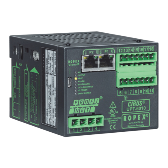
CIRUS
UPT-6010
Operating
instructions
The UPT-6010 temperature controller is a key component in an ULTRA-PULSE system, because
it is responsible for all heat management functions, i.e. controlling the temperature of the heating
element.
Important features
•
Microprocessor technology
•
Complete control via PROFINET interface ("Conformance Class B", IO / RT acc. to IEC 61784-2)
(2 x RJ-45)
•
Automatic zero calibration (AUTOCAL)
•
Automatic configuration of the secondary voltage and current ranges (AUTORANGE)
•
Automatic frequency adjustment
•
Large current and voltage range
•
Booster connection as standard
•
0...10VDC analog output for ACTUAL temperature
•
Alarm function with error diagnosis
•
Heatsaling element alloy and temperature range selectable
•
Cooling system monitored
Industrie-Elektronik GmbH
Adolf-Heim-Str. 4
74321-Bietigheim-Bissingen (Germany)(Alemania)Data subject to changeReservado el derecho a rea-
GB
Tel.: +49 7142 7776-0
Fax: +49 7142 7776-211
E-Mail:
info@ropex.de
Internet:
www.ropex.de
Advertisement
Table of Contents

Related Manuals for Ropex CIRUS UPT-6010


Summary of Contents for Ropex CIRUS UPT-6010
- Page 1 Alarm function with error diagnosis • Heatsaling element alloy and temperature range selectable • Cooling system monitored Industrie-Elektronik GmbH Tel.: +49 7142 7776-0 E-Mail: info@ropex.de Adolf-Heim-Str. 4 Fax: +49 7142 7776-211 Internet: www.ropex.de 74321-Bietigheim-Bissingen (Germany)(Alemania)Data subject to changeReservado el derecho a rea-...
-
Page 2: Table Of Contents
Contents Safety and warning notes ....3 Startup and operation ....17 Use . -
Page 3: Safety And Warning Notes
The temperature coefficient of a CIRUS-Temperatur- Line filter regler is specially adapted to CIRUS heating elements. The use of an original ROPEX line filter is mandatory in The controller is not allowed to be operated order to comply with the standards and provisions with any other heatsealing bands because mentioned in section 1.6 "Standards / CE marking"... -
Page 4: Standards / Ce Marking
Warranty claims must be examined in the factory and components approved by ROPEX are used. If not, then approved by ROPEX. the equipment is operated on the user's own responsibility. -
Page 5: System Description
The trolled transformer so that set = actual. system has been evolved and optimized by ROPEX The fact that purely electrical variables are measured in GmbH in an intensive development process. Users... -
Page 6: Current Transformer
Current transformer The PEX-W2 or PEX-W3 current transformer supplied with the CIRUS UPT-6010 controller is an integral part of the control system. Only this original ROPEX current transformer is allowed to be used. Thanks to its microprocessor based technology, the... -
Page 7: Modifications (Mods)
Designed according to VDE 0570/EN 61558 with a one section bobbin. Optimized for impulse operation with CIRUS temperature controllers. Specified according to the heatsealing application ( ROPEX Application Report). Communication interface CI-USB-1 Interface for connecting a RESISTRON temperature controller with diagnostic inter- face (DIAG) to the PC (USB port). -
Page 8: Technical Data
Heatsealing element The temperature range and temperature coefficient settings can also be specified type and temperature by means of the ROPEX visualization software (section 9.11 "Diagnostic range interface / visualization software" on page 34) in addition to the rotary coding... - Page 9 Technical data Cuttent consumption = 5A (duty cycle = 100%) (primary current of = 25A (duty cycle = 20%) impulse transformer) Power dissipation Max. 20W Ambient temperature +5…+45°C Degree of protection IP20 Installation A minimum safety clearance of 20mm all round (e.g.
-
Page 10: Dimensions
Dimensions Dimensions 75.0 90.0 Page 10 UPT-6010... -
Page 11: Installation
( Application Report). performed by technically trained, skilled 6. Use only ROPEX impulse transformers or transfor- persons who are familiar with the associated risks mers approved by ROPEX. Please note the power, and warranty provisions. - Page 12 Installation PROFINET-Controller using a cable according to. 6. Make sure that the wiring conforms to the relevant national and international installation regulations. Check the tightness of all the system connec- tions, including the terminals for the impulse transformer windings. Page 12 UPT-6010...
-
Page 13: Power Supply
Use transformers with a one section bobbin. The power, duty cycle and voltage values must be deter- SEC. mined individually according to the application ( ROPEX Application Report and "Accessories" leaflet for impulse transformers). Wiring The wire cross-sections depend on the application (... -
Page 14: Line Filter
CE mark. The wiring instructions contained in section 7.4 "Power ROPEX line filters are specially optimized for use in supply" on page 13 must be observed. RESISTRON control loops. Providing that they are Large cross-section wire to ground max. -
Page 15: Wiring Diagram (Standard)
Installation Wiring diagram (standard) Line filter LF-xx480 UPT-6010 LINE Ethernet PORT 1 (RJ45) Ethernet module electrically isolated prim. Shield Impulse Ethernet transformer PORT 2 (RJ45) (for assignment sec. see PORT 1) Ground Heat- Must be grounded sealing externally to band prevent twisted electrostatic... -
Page 16: Wiring Diagram With Booster Connection
Installation Wiring diagram with booster connection Line filter LF-xx480 UPT-6010 LINE Ethernet PORT 1 (RJ45) Booster Ethernet twisted module Max. length 1m electrically isolated prim. Shield Impulse Ethernet transformer PORT 2 (RJ45) (for assignment sec. see PORT 1) Ground Heat- Must be grounded sealing externally to... -
Page 17: Startup And Operation
(or several voltage and current ranges times) through the PEX-W2 or PEX-W3 current trans- The secondary voltage and current ranges are former ( ROPEX Application Report). automatically configured by the automatic calibration UPT-6010 Page 17... - Page 18 If the switch is set to "9", more temperature ranges and alloys can be selected by means of the ROPEX Rotary coding Station name visualization software ( see section 9.11 "Diagnostic switch interface / visualization software"...
-
Page 19: Heating Element
URATION" position is selected, the behavior of the appears when the controller is switched on alarm output can be configured in more detail by means ( section 9.17 "Error messages" on page 37). ROPEX visualization software ( see section 9.11 "Diagnostic interface / visualization soft- ware"... -
Page 20: Startup Procedure
It does not go out again section 8.2 "Controller configuration" on page 17 until it detects an active communication. and ROPEX Application Report). Repeat the calibration after the controller has been configured If the red "ALARM" LED lights up for 0.3s in correctly. - Page 21 Startup and operation The controller is functioning correctly if the 11. The heatup process and the temperature control temperature (which corresponds to the signal must be optimized by means of setting the correc- change at the analog output or the actual value in tion factor Co in the parameter data (GSDML file) or the PROFINET protocol) has a harmonious motion, the acyclic services (...
-
Page 22: Controller Functions
Lit during heating phase. (yellow LED) ALARM Lit or blinking to indicate fault. www.ROPEX.de (Red LED) In addition to the functions shown in the diagram by the LEDs. These states are described in detail in the above, various controller operating states are indicated... - Page 23 Controller functions BLINKS slowly (1Hz) BLINKS fast (4Hz) Lit continuously AUTOCAL requested but "RS" bit is set (reset) function disabled (e.g. AUTOCAL executing AUTOCAL START active) (yellow) LED blinks with a different frequency: Supply voltages incorrect (too low) START requested but function is locked (e.g.
-
Page 24: Profinet Communication
The device master files and the associated image files (.BMP) (for visualization in the configuring tool) However, if the line voltage is not present can be requested by e-mail (support@ropex.de) or (e.g. if it is switched off in order to open a downloaded from our website (www.ropex.de). -
Page 25: Communication Protocol
Controller functions Communication protocol information and the control functions, to enable it to be decoded more easily by the PROFINET controller. The communication protocol consists of 2x16 bit input Bits 0…7 form the low byte and bits 8…15 the words and 3x16 bit output words (from the point of view high byte ("INTEL format"). - Page 26 Controller functions 9.5.1 Automatic zero calibration Reasons for disabled AUTOCAL function: "AUTOCAL" (AC) 1. An "AUTOCAL" request cannot be processed until 10 seconds after the controller is switched on. Owing to the automatic zero calibration (AUTOCAL) During this time the controller reports "AUTOCAL function, there is no need to adjust the zero point disabled"...
-
Page 27: Output Data
Controller functions 9.5.3 Reset (RS) In contrast to the "RS" bit (RESET), the "MP" bit does not reset any fault signals when it is set. The controller This bit resets the controller if the controller reports a is activated again as soon as the bit is reset, in other fault. - Page 28 Controller functions 9.6.5 Temperature reached (TE) The switching state of the "TO" bit can thus be queried after the "ST" bit has been reset and before The "TE" bit is set if the actual temperature exceeds the start of the next heatsealing cycle. 95% of the set temperature.
-
Page 29: Parameter Data
Controller functions 9.6.9 Error codes Value fault If a fault is signaled ("AL" bit = 1), the error code allows Index Function range the exact cause to be determined. The error code is value contained in the third word at bit positions 0…9 External module / Off, on (... - Page 30 TCR = 1700ppm/K, input data ( section 9.5.1 "Automatic zero calibration e.g. CIRUS "AUTOCAL" (AC)" on page 26). PC configuration PC configuration You do not need to execute the AUTOCAL (ROPEX (ROPEX function after changing the calibration visualization visualization temperature.
- Page 31 UPT sealing bar from being damaged with the lowest value (50%) or with the value recom- beyond repair. mended in the ROPEX Application Report minus 25% – to the indicated hold value = set temperature. The maximum value of the setting range is...
- Page 32 ACTUAL temperature is indicated until the end of The lower and upper tolerance band limits the first heating phase. cannot be set in the ROPEX visualization 3. "2 s" software. The same limits apply as for the TO bit. This...
-
Page 33: Undervoltage Detection
PROFINET communication and the digital temperature display Trouble-free operation of the temperature controller is in the ROPEX visualization software. It has no guaranteed within the line voltage and 24VDC supply effect on the ACTUAL temperature that appears at voltage tolerances specified in section 5 "Technical... -
Page 34: Booster Connection
An interface with a 6-pole Western socket is provided heating element. for system diagnostics and process visualization. This The characteristics of the ROPEX ATR-x temperature interface allows a data connection to be set up to the meter (size, scaling, dynamic response) are ideally... -
Page 35: Total Cycle Counter
= 1). This counter can only be displayed and not battery that has to be replaced. reset. It can only be displayed using the ROPEX visualization software ( section 9.11 "Diagnostic The controller must remain switched on for at least interface / visualization software"... -
Page 36: System Monitoring / Alarm Output
1. BLINKS fast (4Hz): value does not change any more. The AUTOCAL function should be executed (error If there is a ROPEX analog temperature meter (i.e codes 104…106, 211, 302, 303). ATR-x) connected to the analog output of the controller, 2. -
Page 37: Error Messages
The 3-digit error numbers described below can be displayed via the PROFINET interface and Invalid error messages may appear when the using ROPEX visualization software controller is switched off owing to the ( section 9.11 "Diagnostic interface / visualization undefined operating state. - Page 38 Controller functions Teil 1 von 3: Error messages (faults) NOTE: The specified error messages are initially output as faults (stable error voltage level at the actual value output; alarm LED lit continuously; alarm relay is energized). Act. value Action Action if machine Error output;...
- Page 39 Controller functions Teil 2 von 3: Error messages (warnings) NOTE: The specified error messages are initially output as warnings (actual value output jumps back and forth between two values; alarm LED blinks; alarm relay is de-energized). When the "START" signal is activated, the warning changes to a fault (actual value output no longer jumps back and forth, see bold italic values;...
-
Page 40: Fault Areas And Causes
Controller functions Teil 3 von 3: Error messages (warnings) NOTE: The specified error messages are initially output as warnings (actual value output jumps back and forth between two values; alarm LED blinks; alarm relay is de-energized). When the "START" signal is activated, the warning changes to a fault (actual value output no longer jumps back and forth, see bold italic values;... - Page 41 Controller functions The table below explains the possible fault causes. Fault area Explanation Possible causes Load circuit interrupted after U - Wire break, heating element break - Contact to heating element is defective pickoff point PEX-W2/-W3 current transformer measurement cable from current transformer interrupted signal interrupted - Wire break, triac in controller defective Primary circuit interrupted...
-
Page 42: Factory Settings
Factory settings Factory settings The UPT-6010 CIRUS temperatue controller is config- ured at the factory as follows: Rotary coding switch Heating element alloy: Alloy A20 Temperature range: 300°C heating element alloy Rotary coding switch: „0“ position SWITCH POS. temperature range 300°C Jumper Fault relay is energized at alarm... -
Page 43: How To Order
Line filter LF- . . 480 06: Continuous current 6A, 480VAC, Art. No. 885500 35: Continuous current 35A, 480VAC, Art. No. 885506 Impulse transformer See ROPEX Application Report for design and ordering information Communication interface CI-USB-1 Art. No. 885650 Temp. meter ATR - . -
Page 44: Index
Index Index Numbers Fault Fault diagnosis 24VDC supply voltage Fault relay Fuse "AA" bit "AC" bit GSDML file Actual value Actual value output "AG" bit "AL" bit Heating element Alarm output Heating element type Alloy Heating time limit Ambient temperature Heatup timeout Analog temperature meter Application... - Page 45 Index Temperature coefficient Temperature diagnosis "RA" bit Temperature meter Replacing the heating element Temperature OK Reset Temperature range "RS" bit Temperature reached Time Time stamp Set point "TO" bit Standby mode Total cycle counter Start Transformer "START" bit Type of construction Starting temperature Startup and operation System diagnosis...
Need help?
Do you have a question about the CIRUS UPT-6010 and is the answer not in the manual?
Questions and answers