Ropex RESISTRON RES-440 Operating Instructions Manual
Hide thumbs
Also See for RESISTRON RES-440:
- Operating instructions manual (89 pages) ,
- Replacement instructions manual (7 pages)
Table of Contents
Advertisement
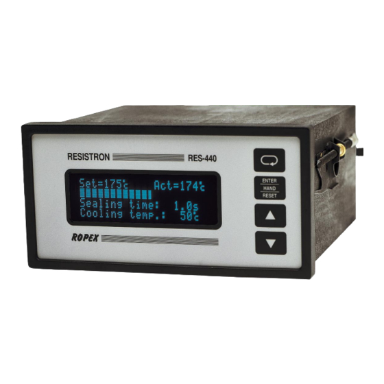
RESISTRON
RES-440
Operating
Instructions
Important features
•
Microprocessor technology
•
LC display (green), 4 lines, 20 characters, (multilingual)
Alternatively:
VF display (blue), 4 lines, 20 characters, (multilingual)
•
Automatic zero calibration (AUTOCAL)
•
Automatic optimization (AUTOTUNE)
•
Automatic frequency adjustment
•
Large current and voltage range
•
Booster connection as standard
•
Heatsealing band alloy and temperature range selectable
•
Time control, heatsealing time and cooling time settable
•
Preheating
•
Configurable relay output, e.g. "end of cycle"
•
Time or temperature-controlled cooling phase
•
Signal output for "Temperature OK"
•
0...10VDC analog output for ACTUAL temperature
•
Alarm function with fault diagnosis
Identical design to and compatible with RES-222, -230, -241, -242
Industrie-Elektronik GmbH
Gansäcker 21
D-74321-Bietigheim-Bissingen (Germany)
GB
Tel: +49/(0)7142/7776-0
Fax: +49/(0)7142/7776-19
E-Mail:
info@ropex.de
Internet:
www.ropex.de
Data subject to change
Advertisement
Table of Contents

Related Manuals for Ropex RESISTRON RES-440


Summary of Contents for Ropex RESISTRON RES-440
- Page 1 0…10VDC analog output for ACTUAL temperature • Alarm function with fault diagnosis Identical design to and compatible with RES-222, -230, -241, -242 Industrie-Elektronik GmbH Tel: +49/(0)7142/7776-0 E-Mail: info@ropex.de Gansäcker 21 Fax: +49/(0)7142/7776-19 Internet: www.ropex.de D-74321-Bietigheim-Bissingen (Germany) Data subject to change...
-
Page 2: Table Of Contents
Contents Safety and warning notes ....3 Controller functions ....23 Use . -
Page 3: Safety And Warning Notes
The resistance of the heatsealing band which is used must have a positive minimum Only the original ROPEX PEX-W2 current temperature coefficient in order to guarantee transformer may be used. Other transformers trouble-free... -
Page 4: Line Filter
Line filter DIN EN 61010-1 Safety provisions for electrical The use of an original ROPEX line filter is mandatory in (VDE 0411-1) measuring, control and laboratory order to comply with the standards and provisions devices (low voltage directive). -
Page 5: Principle Of Operation
Principle of operation • etc. • Increased machine capacity The use of RESISTRON temperature controllers • Extended life of the heatsealing bands and teflon coatings results in: • Simple operation and control of the sealing process • Repeatable quality of the heatseals under any conditions Principle of operation The resistance of the heatsealing band, which is... -
Page 6: Description Of The Controller
Description of the controller Description of the controller microprocessor technology endows The process data is represented on an LC display with RESISTRON temperature controller RES-440 with 4 lines and 20 characters. Devices with a VF display previously unattainable capabilities: are available as an option. Various display languages can be selected. - Page 7 Designed according to VDE 0570/EN 61558 with a one-section bobbin. Optimized for impulse operation with RESISTRON temperature controllers. Specified according to the heatsealing application (! ROPEX Application Report). Booster B-xxx400 External switching amplifier, necessary for high primary currents (continuous current > 5A, pulsed current > 25A).
-
Page 8: Modifications (Mods)
Accessories and modifications Modifications (MODs) MOD 01 Amplifier secondary voltages Owing to its universal design, the RESISTRON = 0.25…16VAC). This modification is necessary, temperature controller RES-440 is suitable for a very example, very short low-resistance wide range of heatsealing applications. heatsealing bands. -
Page 9: Technical Data
Technical data Technical data Type of construction Housing for front panel mounting Dimensions (W x H): 144 x 72mm; depth: 161mm (incl. terminals) Line voltage All controllers manufactured as of January 2004: 115VAC version: 115VAC -15%…120VAC +10% (equivalent to 98…132VAC) 230VAC version: 230VAC -15%…240VAC +10% (equivalent to 196…264VAC) 400VAC version: 400VAC -15%…415VAC +10% (equivalent to 340…456VAC) All controllers manufactured up to December 2003:... - Page 10 Technical data Maximum load = 5A (duty cycle = 100%) (primary current of = 25A (duty cycle = 20%) impulse transformer) Display LC display (green), 4 lines, 20 characters, alternatively: VF display (blue), 4 lines, 20 characters Ambient temperature +5…+45°C Degree of protection Front: IP42 (IP65 with transparent front cover, Art.
-
Page 11: Dimensions/Front Panel Cutout
Dimensions/front panel cutout Dimensions/front panel cutout panel cutout outline dimensions front frame ±0.2 ±0.2 x 68 rubber seal mounting clamp terminal wires terminal blocks terminal blocks front panel terminal wires front frame DIP-switch to select U , I RES-440 Page 11... -
Page 12: Installation
4. Wire the system in accordance with the instructions in Kap. 8.3 „Power supply“ auf Seite 14, Kap. 8.6 „Wiring diagram (standard)“ auf Seite 16 and the Installation procedure ROPEX Application Report. information provided in Kap. 8.2 „Installation steps“ auf Seite 13 Proceed as follows to install the RESISTRON must be heeded additionally. -
Page 13: Installation Steps
Installation Installation steps Use heatseal bands with suitable temperature coefficient Heatseal element push-on with coppered ends connectors Heatsealing band R= f (T) No additional Connect U measuring resistance wires directly to in secondary Note heatsealing band ends circuit number Sufficient wire of turns Twisted cross-section... -
Page 14: Power Supply
Use transformers with a one-section bobbin. The power, duty cycle and voltage values must be determined individually according to the application SEC. (! ROPEX Application Report and "Accessories" leaflet for impulse transformers). Wiring The wire cross-sections depend on the application (! ROPEX Application Report). -
Page 15: Line Filter
CE mark. The wiring instructions contained in section 8.3 "Power ROPEX line filters are specially optimized for use in supply" on page 14 must be observed. RESISTRON control loops. Providing they are installed... -
Page 16: Wiring Diagram (Standard)
Installation Wiring diagram (standard) Line filter LF-xx480 RES-440 LINE (also with MOD 01) RELAY K1 100VDC/1.5A 240VAC/1.5A 2x 47nF/560R ALARM OUTPUT max. 50V/0.2A Contact closed or prim. opened by ALARM (see configuration) Impulse transformer sec. PREHEAT Heat- with 24VDC signal sealing band twisted... -
Page 17: Wiring Diagram With Booster Connection
Installation Wiring diagram with booster connection Line filter LF-xx480 RES-440 LINE (also with MOD 01) Booster RELAY K1 100VDC/1.5A 240VAC/1.5A 2x 47nF/560R ALARM OUTPUT max. 50V/0.2A Contact closed or prim. opened by ALARM (see configuration) Impulse transformer sec. PREHEAT Heat- with 24VDC signal sealing band... -
Page 18: Startup And Operation
DIP switches (on rear of controller) Nameplate Clips Display Rear view of the controller Printed wiring diagram ROPEX 19 20 21 22 23 24 25 26 16 17 18 RES- 440 ( A ) DIP-SWITCH 30 - 100 U ( V ) - Page 19 Set the DIP switches for matching the secondary You can find the exact configuration of the voltage U and the secondary current I to the correct DIP switches in the ROPEX Application position for your application. Report calculated for your particular application. Factory settings Rear view...
-
Page 20: Heatsealing Band
Startup and operation 9.3.6 Relay K1 (without time control) 4. Temperature coefficient 570ppm, 0…300°C (software revision 019 or higher) The function of relay K1 is specified with step 29 in the 5. Temperature coefficient 630ppm, 0…300°C Configuration menu: (software revision 019 or higher) 6. -
Page 21: Startup Procedure
3. The settings of the DIP switches on the controller (display in home position) to heat for approximately depend on the ROPEX Application Report and the 1 second. After recooling, the controller usually heatsealing band that is used (Kap. 9.3 „Controller indicates a value less than 20°C. - Page 22 In this case the controller configuration is incorrect (! Kap. 9.3 „Controller configuration“ auf Seite 18 Alarm signal with error codes Go to 8 and ROPEX Application Report). Repeat the zero 104…106, 111…113, 211 point calibration after the controller has been configured correctly.
-
Page 23: Controller Functions
Save values HAND HAND function: Manual mode RESET RESET function: Reset after alarm ROPEX "UP" and "DOWN" keys for setting values Press (< 2 sec.): Slow change Hold (> 2 sec.): Fast change LC display, 4 lines, multilingual optional: VF d isplay, 4 lines, multilingual 10.2... - Page 24 Controller functions 10.2.2 Display in home position digital value and the ACTUAL temperature as a digital value and a dynamic bar. If time control (timer function) If no settings are entered on the controller and no alarm is active, the time control settings are also displayed. signals are present, the display is in the home position, in other words it indicates the SET temperature as a Specified heatsealing...
-
Page 25: Navigation In The Menus
Controller functions 10.3 Navigation in the menus structure, providing a controller alarm is not active. In this case, the Alarm menu is opened instead. If the display is in the home position or an alarm is 10.3.1 Navigation in menus without an indicated and you press the "MENU"... - Page 26 Controller functions 10.3.2 Navigation in menus with an alarm can then activate the "AUTOCAL" function by pressing the "ENTER" key (! Kap. 10.8 „Automatic zero If an alarm is signaled, the controller switches to the calibration (AUTOCAL)“ auf Seite 34). Alarm menu.
-
Page 27: Menu Structure
Controller functions 10.4 Menu structure Settings Configuration Power-up message Language Home position Factory settings Heatsealing temp. Alloy/range Preheating temp. Max. temperature Starting delay Set point reached Sealing time 25 Set point exceeded Cooling value Time control 1) Time control ON Hold mode 2) Time control OFF Cooling mode... -
Page 28: Menu Steps
Controller functions 10.5 Menu steps Name Description Setting range Home position The specified set value and the current actual value are displayed in digital form. The actual value is also represented as a dynamic bar. If time control (step 26) is active, the heatsealing time and the cooling value are also displayed. - Page 29 Controller functions Name Description Setting range Cooling value The cooling value can be specified here according to the cooling mode (absolute, relative, time) selected with step 27. • Absolute: The cycle ends if the "cooling 50°C to maximum temperature" falls below the set value (in °C). temperature (step 23) •...
- Page 30 Controller functions Name Description Setting range Language The desired display language can be selected with English this menu step. German Italian SW revision 015 or higher also: French, Spanish, Dutch, Danish, Finnish, Swedish, Greek, Turkish. SW revision 024 or higher also: Portuguese.
- Page 31 Controller functions Name Description Setting range Set point exceeded If the actual value is less than the switching +5K…+99K (high limit) threshold specified here and greater than the threshold set with step 24, the "Temperature OK" output is activated. The value is entered in Kelvins (K) and added to the set point in order to calculate the switching threshold.
- Page 32 Controller functions Name Description Setting range Relay K1 function The energizing behavior of relay K1 can be configured as follows: Time control OFF: • K1 is not activated Relay K1 OFF • K1 is energized if the "Temperature OK" output Relay K1 active if Tact = is active Tset...
-
Page 33: Temperature Setting
Controller functions 10.6 Temperature setting (set point In addition, the RES-440 controller outputs an analog 0…10VDC signal, which is proportional to the real selection) ACTUAL temperature, at terminals 23+24 The heatsealing temperature can be set on the RES-440 controller by means of the setting in menu RES-440 step 1. -
Page 34: Automatic Zero Calibration
10.8 Automatic zero calibration heatsealing band. (AUTOCAL) The characteristics of the ROPEX ATR-x temperature meter (size, scaling, dynamic response) are ideally Owing to the automatic zero calibration (AUTOCAL) suited to this application (! Kap. 5 „Accessories and function, there is no need to adjust the zero point modifications“... -
Page 35: Start" Signal (Heat)
Controller functions The message "- Calibration - Please wait..." appears temperature until the signal is deactivated again. on the display while the "AUTOCAL" function is This process can also be started independently of executing and a counter counts down from 13 to 0. The the "START"... -
Page 36: Preheat" Signal
Controller functions The set point that is selected for the heatsealing • By means of a 24VDC signal at terminals 20+22. temperature (step 1 in the Settings menu) must be greater than 40°C. If not, the heatsealing band will not 24VDC RES-440 be heated up. -
Page 37: Temperature Ok" Signal
Controller functions "PREHEAT" signal Actual value Set+ ∆ϑ 24VDC upper Set+ ∆ϑ lower "START" signal 24VDC Time Output Terminals 20+21 Conductive ACTUAL Not conduct. temperature Time The "Temperature OK" signal is available at terminals 20+21 as a digital control signal. = Preheating temperature (PREHEAT) +24VDC = Heatsealing temperature... -
Page 38: Hold Mode
Controller functions The various hold modes are shown below: START signal 24VDC The cycle counter is reset to 0 if the "ENTER" key is pressed or if the maximum count of 999.999.999 cycles ACTUAL is exceeded. temp. 10.13 Hold mode The behavior of the digital indication of the ACTUAL ACTUAL indication temperature in the home position can be changed with... -
Page 39: Disabling The Configuration Menu
Controller functions 10.14 Disabling the Configuration menu 75%, 100%) with the "UP" and "DOWN" keys. The factory setting is 75%. (Software revision 010 or higher) It is possible to disable all changes to values/ parameters in the Configuration menu. This prevents the controller configuration from being tampered with by unauthorized persons. -
Page 40: Booster Connection
Controller functions 10.17 Booster connection activated - the timeout is interrupted. The RES-440 controller has a connection for an If time control is on, activating the "START" signal starts external switching amplifier (booster) as standard. This the internally parameterized timeout. This timeout connection (at terminals 1+2) is necessary for high comprises: primary currents (continuous current >... - Page 41 Controller functions heating phase. A direction arrow indicates the active When the "START" signal is activated, the controller process. waits for the time specified with this menu step to elapse before commencing the heating process. START signal 24VDC The active cooling phase is subsequently marked with ACTUAL the direction arrow at the end of the heating phase.
- Page 42 Controller functions heatsealing time is equal to the active time of the The various cooling modes are shown below: "START" signal. START signal START 24VDC signal 24VDC ACTUAL temp. ACTUAL temp. Cooling mode = Heating phase = Cooling phase in °C Absolute 10.18.4 Setting the cooling mode Various criteria for the end of the cooling phase can be...
- Page 43 Controller functions The possible settings are as follows: step 3). The specified heatsealing time does not start, however, until the ACTUAL temperature of the 1. "Cooling temp. in °C" heatsealing band reaches 95% of the SET (if setting with menu step 27 = "Absolute") temperature.
- Page 44 Controller functions 2. "When temperature reached"(•) The possible settings are shown below: The normally open contact of relay K1 closes when START the ACTUAL temperature reaches 95% of the SET signal temperature and remains closed until the end of the 24VDC parameterized timeout (i.e.
- Page 45 Controller functions 10.18.8 Preheating (with time control) never reached, i.e. the internal timeout does not elapse. If time control is active, the preheating temperature If the cooling temperature is required to be lower than (! Kap. 10.10 „"PREHEAT" signal (preheating without the preheating temperature, the "PREHEAT"...
-
Page 46: System Monitoring/Alarm Output
Controller functions 10.19 System monitoring/alarm output The timing sequence can be represented as follows: START signal (foot switch) To increase operating safety and to avoid faulty heatsealing, controller incorporates special hardware and software features that facilitate selective fault detection and diagnosis. Both the external wiring and the internal system are monitored. -
Page 47: Error Messages
Controller functions 10.20 Error messages activated in one of these states, the voltage value does not change any more. Selective fault detection and indication can thus be The table below shows how the analog voltage values implemented simply and inexpensively using the that appear at the actual value output are assigned to analog input of a PLC with a corresponding error the faults that have occurred. - Page 48 Controller functions Page 48 RES-440...
-
Page 49: Fault Areas And Causes
Controller functions 10.21 Fault areas and causes Temperature controller HARDWARE The table below explains the possible fault causes. Fault area Explanation Possible causes Load circuit interrupted after U - Wire break, heatsealing band break - Contacting to heatsealing band defective pickoff point "... -
Page 50: Factory Settings
Factory settings Factory settings The RESISTRON temperature controller RES-440 is configured in the factory as follows: DIP switches = 6…60VAC = 30…100A secondary voltage and current I DIP switches: 2 ON 1, 3, 4, 5 OFF Values in the Settings Settings menu and Configuration Step 1... -
Page 51: Maintenance
Maintenance The language which is selected with step 20 in the Configuration menu remains set even if the factory settings are restored. Maintenance The controller requires no special maintenance. the impulse transformer – is recommended. Dust Regular inspection and/or tightening of the terminals – deposits on the controller can be removed with dry including the terminals for the winding connections on compressed air. -
Page 52: How To Order
Line filter LF- . . 480 06: Continuous current 6A, 480VAC, Art. No. 885500 35: Continuous current 35A, 480VAC, Art. No. 885506 Impulse transformer See ROPEX Application Report for design and ordering information Temp. meter ATR- . 3: 300°C range, Art. No. 882130 5: 500°C range, Art. -
Page 53: Index
Index Index Accessories Impulse heatsealing method Actual value output Impulse transformer Adapter for top hat rail mounting Installation Additional relay K1 Installation procedure Alarm output Installation regulations Alarm relay Alloy Ambient temperature Line filter Analog temperature meter Line frequency Application Line voltage Application Report AUTOCAL... - Page 54 Index Time control Timer function View of controller Transformer Type of construction Wiring Wiring diagram Undervoltage detection Page 54 RES-440...
Need help?
Do you have a question about the RESISTRON RES-440 and is the answer not in the manual?
Questions and answers