Table of Contents
Advertisement
Quick Links
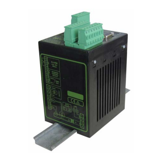
CIRUS
UPT-606
Operating
instructions
The UPT-606 temperature controller is a key component in an ULTRA-PULSE system, because it
is responsible for all heat management functions, i.e. controlling the temperature of the heating
element.
Important features
•
Microprocessor technology
•
Complete control via PROFIBUS-DP interface
•
Automatic zero calibration (AUTOCAL)
•
Automatic configuration of the secondary voltage and current ranges
(AUTORANGE, as of Software revision 100)
•
Automatic frequency adjustment
•
Large current and voltage range
•
Booster connection as standard
•
0...10VDC analog output for ACTUAL temperature
•
Alarm function with fault diagnosis
•
Heatsealing element alloy and temperature range selectable
•
Cooling system monitored
Industrie-Elektronik GmbH
Gansäcker 21
D-74321-Bietigheim-Bissingen (Germany)(Германия)(Alemania)
GB
TelТел: +49/(0)7142/7776-0
FaxФакс: +49/(0)7142/7776-211 InternetИнтернет:
E-MailЭл. почта:
info@ropex.de
www.ropex.de
Data subject to changeПраво на
Advertisement
Table of Contents

Related Manuals for Ropex CIRUS UPT-606


Summary of Contents for Ropex CIRUS UPT-606
- Page 1 0…10VDC analog output for ACTUAL temperature • Alarm function with fault diagnosis • Heatsealing element alloy and temperature range selectable • Cooling system monitored Industrie-Elektronik GmbH TelТел: +49/(0)7142/7776-0 E-MailЭл. почта: info@ropex.de Gansäcker 21 FaxФакс: +49/(0)7142/7776-211 InternetИнтернет: www.ropex.de D-74321-Bietigheim-Bissingen (Germany)(Германия)(Alemania) Data subject to changeПраво на...
-
Page 2: Table Of Contents
Contents Safety and warning notes ....3 Startup and operation ....16 Use . -
Page 3: Safety And Warning Notes
Line filter controller is specially adapted to CIRUS heating ele- ments. The use of an original ROPEX line filter is mandatory in order to comply with the standards and provisions The controller is not allowed to be operated mentioned in section 1.6 "Standards / CE marking" on with any other heatsealing bands because page 4. -
Page 4: Standards / Ce Marking
Warranty claims must be examined in the factory and components approved by ROPEX are used. If not, then approved by ROPEX. the equipment is operated on the user's own responsibility. -
Page 5: System Description
The trolled transformer so that set = actual. system has been evolved and optimized by ROPEX The fact that purely electrical variables are measured in GmbH in an intensive development process. Users... -
Page 6: Current Transformer
Current transformer The PEX-W2 or PEX-W3 current transformer supplied with the CIRUS UPT-606 controller is an integral part of the control system. Only this original ROPEX current transformer is allowed to be used. Thanks to its microprocessor based technology, the... -
Page 7: Modifications (Mods)
Designed according to VDE 0570/EN 61558 with a one section bobbin. Optimized for impulse operation with CIRUS temperature controllers. Specified according to the heatsealing application ( ROPEX Application Report). Communication interface CI-USB-1 Interface for connecting a RESISTRON temperature controller with diagnostic inter- face (DIAG) to the PC (USB port). -
Page 8: Technical Data
Heatsealing element The temperature range and temperature coefficient settings can also be specified type and temperature by means of the ROPEX visualization software ( section 9.11 "Diagnostic inter- range face/visualization software (as of software revision 100)" on page 39) in addition... - Page 9 Technical data +5…+45°C Ambient temperature IP20 Degree of protection If several controllers are installed on one top hat Installation rail (DIN TS35 rail), a clearance of at least 20mm should be allowed between them. The moving clip required for fastening must be facing down for mounting on a horizontal top hat rail.
-
Page 10: Dimensions
5. Ensure an adequate cable cross-section for the pri- mary and secondary circuits ( Application Report). Installation and startup may only be per- 6. Use only ROPEX impulse transformers or transfor- formed by technically trained, skilled per- mers approved by ROPEX. Please note the power,... - Page 11 7.6 "Wiring diagram (standard)" on page 14 transformer windings. and the ROPEX Application Report. The information provided in section 7.1 "Installation steps" on 6. Make sure that the wiring conforms to the relevant page 10 must also be heeded additionally.
-
Page 12: Power Supply
Use transformers with a one section bobbin. The power, duty cycle and voltage values must be deter- SEC. mined individually according to the application ( ROPEX Application Report and "Accessories" leaflet for impulse transformers). Wiring The wire cross-sections depend on the application (... -
Page 13: Line Filter
CE mark. The wiring instructions contained in section 7.3 "Power ROPEX line filters are specially optimized for use in supply" on page 12 must be observed. RESISTRON control loops. Providing that they are Large cross-section wire to ground max. -
Page 14: Wiring Diagram (Standard)
Installation Wiring diagram (standard) Line filter LF-xx480 PROFIBUS-PLUG SUB-D / 9-POLE UPT-606 LINE Shield (Auxiliary supply) M24 PROFIBUS DGND controller electrically (+5V) VP isolated (Auxiliary supply) P24 prim. Impulse transformer +24VDC sec. AUXILIARY SUPPLY Heat- sealing element twisted ALARM OUTPUT max. -
Page 15: Wiring Diagram With Booster Connection
Installation Wiring diagram with booster connection Line filter LF-xx480 PROFIBUS-PLUG SUB-D / 9-POLE UPT-606 LINE Shield Booster (Auxiliary supply) M24 PROFIBUS DGND controller electrically (+5V) VP isolated (Auxiliary supply) P24 prim. Impulse transformer +24VDC sec. AUXILIARY SUPPLY Heat- sealing element twisted ALARM OUTPUT max. -
Page 16: Startup And Operation
The secondary voltage and current ranges are auto- You can find the exact configuration of the matically configured by the automatic calibration func- DIP switches in the ROPEX Application tion (AUTOCAL). The voltage is configured in the range Report calculated for your particular application. - Page 17 500°C (switch position 4) is available on con- more temperature ranges and alloys can be selected trollers as of software revision 100 only. by means of the ROPEX visualization software ( see section 9.11 "Diagnostic interface/visualization soft- The setting of the rotary coding switch for the ware (as of software revision 100)"...
-
Page 18: Heating Element
100), the behavior of the alarm output can be troller up to software revision 015. The other func- configured in more detail by means of the ROPEX visu- tions of the controller (e.g. heating, AUTOCAL etc.) alization software ( see section 9.11 "Diagnostic are not impaired by this. -
Page 19: Startup Procedure
DIP switches on the controller are All power supply leads must be disconnected from the indicated in the ROPEX Application Report and CIRUS temperature controller in order to replace the depend on the heating element that is used. - Page 20 BLINKS fast Go to 10 ( section 8.2 "Controller configuration" on page 16 (4Hz) and ROPEX Application Report). Repeat the cali- Lit conti- Fault diagnosis bration after the controller has been configured cor- nuously ( section 9.13) rectly.
-
Page 21: Controller Functions
AUTOCAL Remains lit for duration of CIRUS (yellow LED) AUTOCAL process. UPT- 606 Temperature controller ROPEX 24V SUPPLY Lit if external 24VDC power (green LED) supply is present. Tel:+49(0)7142-7776-0 BUS PWR OK Lit if internal 5VDC power (green LED) - Page 22 Yellow LED, lit during heating phase. RESISTRON Red LED, lights up or blinks to indicate alarm. μP-Controller ROPEX Green LED, remains lit as long as PROFIBUS data is beeing exchanged with master. INDUSTRIE - ELEKTRONIK In addition to the functions shown in the diagram by the LEDs.
-
Page 23: Profibus Communication „Up To Sw- Rev 015"/"As Of Sw-Rev 100
(.GSD or .GSE) on a diskette. They can also be reque- supply (terminals 5+7 and PROFIBUS connector pins sted by E-Mail (support@ropex.de) or they can be 7+2) and the line voltage are present. If the line voltage downloaded from our Homepage (www.ropex.de). - Page 24 Controller functions 9.4.1 "Compact" protocol with 4-Bit error code The 16-bit input data from the PROFIBUS master to the UPT-606 contains the set point and the control functions and has the following structure: Control function Spare Set point / AC temperature Name: Bit no.: The 16-bit output data from the UPT-606 to the PRO-...
- Page 25 Controller functions 9.4.3 "Extended" protocol with 4-Bit error code The extended protocol transfers 2x16bits. The 2x16- bit input data contains the set point in word and the control functions in word : Spare Set point / AC temperature Name: Bit no.: ...
-
Page 26: Input Data
Controller functions The 2x16-bit output data contains the actual value in word and the error code and status information in word : Actual value (signed) Name: Bit no.: Error code Status information Name: Bit no.: Input data The AUTOCAL request ("AC"... - Page 27 Controller functions 5. AUTOCAL cannot be activated if error codes 1…3, software revision 100: 5…7 (As of software revision 100 also: 101…103, 201…203, 901, 913) are evaluated and output by the 201…203, 801, 9xx) occur at start-up. AUTOCAL fault diagnosis function. The power section is not acti- cannot be activated with error codes 5…7 (As of vated in this state and no measuring impulses are software revision 100 also: 201…203, 801, 9xx) if...
-
Page 28: Output Data
Controller functions In contrast with the "RS" bit (RESET), the "MP" bit does 9.6.5 Temperature OK (TO) not reset any error message when it is set. The con- The UPT-606 checks whether the actual temperature is troller is activated again as soon as the bit is reset, in within a settable tolerance band ("OK"... - Page 29 „TO“ bit can be set via the stics function also sends error messages to the PRO- ROPEX visualization software. As of software revision FIBUS master. The error messages corresponding to 103 the configuration for the „TO“ bit is set in the PRO-...
-
Page 30: Parameter Data
Controller functions Parameter data fault Possible The parameter data contains values for selecting the Function value values heatsealing element alloy, the temperature range, the upper and lower tolerance band limits for temperature monitoring, the calibration temperature and the optional Maximum 100°... - Page 31 (value 4) are only available on controllers as of software revision 100. 9.7.5 Heating time limit The setting „ROPEX visualization software“ The heating time limit provides additional protection (value 9) is available on controllers as of soft- against unwanted permanent heating. The controller...
- Page 32 Slowly increase the correction factor – starting either in the PROFIBUS master. with the lowest value (50%) or with the value recom- mended in the ROPEX Application Report minus 25% 9.7.7 Measuring impulse duration – to the indicated hold value = set temperature.
- Page 33 Controller functions perature and cooling time) for productive operation. 9.7.11 Maximum starting temperature The starting temperature should be set to approxi- (as of software revision 100) mately 50% of the heatsealing temperature for the trial In the PROFIBUS paramter data (GSD-file) or in the run, to enable the optimum working parameters to be DPV1 protocol extension the maximum starting tempe- established correctly.
- Page 34 ( section 9.13 "Error mes- temperature on the actual value output and the data sages" on page 40). record in the graphics window of the ROPEX visua- lization software is not affected. Actual value 95% of Set...
-
Page 35: Dpv1 Protocol Extension (As Of Gsd Version V2.0)
Controller functions The various hold modes are shown below: The "hold mode" function must be activated by means of the PROFIBUS parameter data „ST“ bit ( section 9.7 "Parameter data" on page 30) or the DPV1 protocol extension ( section 9.8 "DPV1 pro- tocol extension (as of GSD Version v2.0)"... - Page 36 Controller functions be altered on the PLC control unit during the validation 9.8.3 DPV1 parameter data process. The basic controller settings and functions can be set This acyclic service supports both reading and writing with the parameter data in the device master file (GSD of the controller parameters.
- Page 37 Controller functions Slot Index Parameter Value range Temperature coefficient [ppm/K] 400…4000 (1700) Temperatur range 0: 200°C 1: 300°C 2: 400°C 3: 500°C Maximum temperature [°C] 200…500 (300) Temperature diagnosis 0: deactivated 1: activated Temperature diagnosis delay time 0…999 (0) [0.01s steps] Heatup timeout [0.01s steps] 0…999 (0) „TO“...
-
Page 38: Temperature Indication
The characteristics of the ROPEX ATR-3 temperature The UPT-606 supplies an analog 0…10VDC signal, meter (size, scaling, dynamic response) are ideally which is proportional to the real ACTUAL temperature, suited to this application and this instrument should at terminals 17+18. -
Page 39: Diagnostic Interface/Visualization Software (As Of Software Revision 100)
8…11 in the second word damage to the controller. ( section 9.6.9 "Error codes" on page 29). The ROPEX visualization software is described in a Error code output via the 0…10VDC analog separate document. output (terminals 17+18): Since a temperature indication is no longer necessary 9.12... -
Page 40: Error Messages
100. The error messages are differentiated alarms. even more finely in the controller. The 3-digit error codes described in brakets below can be displayed with the ROPEX visualization software ( section 9.11 9.13 Error messages "Diagnostic interface/visualization software (as of soft- ware revision 100)"... - Page 41 Controller functions UPT-606 Page 41...
- Page 42 Controller functions Page 42 UPT-606...
- Page 43 Controller functions UPT-606 Page 43...
- Page 44 Controller functions Page 44 UPT-606...
-
Page 45: Fault Areas And Causes
Controller functions 9.14 Fault areas and causes Temperature controller HARDWARE The table below explains the possible fault causes. Fault area Explanation Possible causes Load circuit interrupted after U - Wire break, heating element break - Contact to heating element is defective pickoff point ... -
Page 46: Factory Settings
Factory settings Fault area Explanation Possible causes - Up to software revision 015: DIP switches 4 + 5 configured incorrectly (I range) signal incorrect - As of software revision 100: I outside permissible range from 30…500A Turns through PEX-W2/-W3 cur- - Check number of turns (two or more turns required for rent transformer incorrect currents <... -
Page 47: Maintenance
Maintenance Rotary coding swit- Station address = 01 ches x 10 station address Top of housing Temperature Temperature diagnosis: deactivated diagnosis Heatup timeout Heatup timeout: deactivated [X] As of software revision 100 and GSD Version v2.0: Setting by means of the PROFIBUS parameter data or the DPV1 protocol extension. -
Page 48: How To Order
Line filter LF- . . 480 06: Continuous current 6A, 480VAC, Art. No. 885500 35: Continuous current 35A, 480VAC, Art. No. 885506 Impulse transformer See ROPEX Application Report for design and ordering information Communiction interface CI-USB-1 Art. No. 885650 Temp. meter ATR- . -
Page 49: Index
Index Index "AA" bit Factory settings "AC" bit Fault areas Actual value Fault diagnosis Actual value output Fuse "AG" bit "AL" bit Alarm Alarm output Alarm relay Alloy Heating element Ambient temperature Heatsealing element type Analog temperature meter Heatup timeout Application Application Report AUTOCAL... - Page 50 Index "TE" bit Temperature coefficient "RA" bit Temperature diagnosis Replacing the heating element Temperature indication Reset Temperature meter "RS" bit Temperature OK Temperature range Temperature reached Secondary current I "TO" bit Secondary voltage U Transformer Set point Type of construction Start "START"...
Need help?
Do you have a question about the CIRUS UPT-606 and is the answer not in the manual?
Questions and answers