Table of Contents
Advertisement
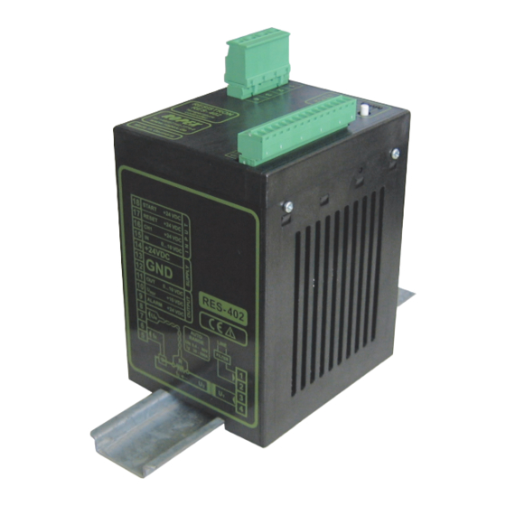
RESISTRON
RES-402
Operating
Instructions
Important features
•
Automatic zero calibration (AUTOCAL)
•
Automatic optimization (AUTOTUNE)
•
Automatic configuration of the secondary voltage and current ranges
(AUTORANGE, as of January 2006)
•
Automatic frequency adjustment
•
Temperature range: 300°C
•
Electrically isolated analog input for set point selection with potentiometer or 0...10VDC
•
Electrically isolated 0...10VDC analog output for ACTUAL temperature
•
24VDC control signals for START, AUTOCAL and RESET with electrical isolation
•
Alarm function
ROPEX Industrie-Elektronik GmbH
Adolf-Heim-Str. 4
74321 Bietigheim-Bissingen (Germany)
Tel.: +49 (0)7142-7776-0
Fax: +49 (0)7142-7776-211
E-Mail:
info@ropex.de
Internet:
https://ropex.de
Data subject to change
Advertisement
Table of Contents

Related Manuals for Ropex RESISTRON RES-402


Summary of Contents for Ropex RESISTRON RES-402
- Page 1 Electrically isolated analog input for set point selection with potentiometer or 0…10VDC • Electrically isolated 0…10VDC analog output for ACTUAL temperature • 24VDC control signals for START, AUTOCAL and RESET with electrical isolation • Alarm function ROPEX Industrie-Elektronik GmbH Tel.: +49 (0)7142-7776-0 E-Mail: info@ropex.de Adolf-Heim-Str. 4 Fax: +49 (0)7142-7776-211 Internet: https://ropex.de...
-
Page 2: Table Of Contents
Contents General information ....3 Startup and operation ....14 Copyright . -
Page 3: General Information
The temperature coefficient must be taken from the ROPEX application report and must be set accordingly. The use of incorrect alloys with a too low temperature coefficient and incorrect coding of the ®... -
Page 4: Impulse Transformer
The use of an original ROPEX line filter is mandatory in order to comply with the directives mentioned in section "DECLARATION OF CONFORMITY" on page 6. This device must be installed and connected according to the instructions contained in section "Power supply"... -
Page 5: Disposal
General information Disposal This device is subject to Directive 2012/19/EU concerning the reduction of the increasing amount of waste electrical and electronic equipment and the disposal of such waste in an environmentally sound way. To guarantee proper disposal and / or the recover of reusable material, please take the device to a designated municipal collection point and observe local regulations. - Page 6 We also wish to point out that the transformer which is used must be designed in accordance with VDE 0551/EN 61558 or UL 5058 for safety reasons. July 12, 2020 J. Kühner (CEO) ROPEX Industrie-Elektronik GmbH Adolf-Heim-Str. 4 74321 Bietigheim-Bissingen (Germany) Page 6...
-
Page 7: Application
Application Application ® This RESISTRON temperature controller is an integral part of the "series 400", the outstanding feature of which is its microprocessor technology. All RESISTRON temperature controllers are used to control the temperature of heating elements (heatsealing bands, beaded bands, cutting wires, heatsealing blades, solder elements etc.), as required in a variety of heatsealing processes. -
Page 8: Installation
4. Wire the system in accordance with the instructions in section 5.3 "Power supply" on page 10, section 5.6 "Aux- iliary voltage" on page 13 and the ROPEX Application Report. The information provided in section 5.2 "Instal- lation steps" on page 9 must be heeded additionally. -
Page 9: Installation Steps
Installation Installation steps Use heatseal bands with suitable temperature coefficient Heatseal element push-on with coppered ends connectors Heatsealing band R= f (T) No additional Connect U measuring resistance wires directly to in secondary Note heatsealing band ends circuit number Sufficient wire of turns Twisted cross-section... -
Page 10: Power Supply
Connect core to ground. Use transformers with a one section bobbin. The power, duty cycle and voltage values must be deter- mined individually according to the application ( ROPEX SEC. Application Report and "Accessories" leaflet for impulse transformers). -
Page 11: Line Filter
ROPEX line filters are specially optimized for use in RESISTRON control loops. Providing that they are installed and wired correctly, they guarantee compliance with the EMC limit values. You can find the exact specification of the line filter in the ROPEX Application Report calculated for your particular heatsealing application. - Page 12 Installation 5.5.1 PEX-W4 terminal wires terminal block Snap-on for DIN-rail 35 x 7.5 mm or 35 x 15 mm (DIN EN 50022) 5.5.2 PEX-W5 Mounting on DIN-rail 35 x 7.5 mm or 35 x 15 mm (DIN EN 50022). Page 12 RES-402 Version 1...
-
Page 13: Auxiliary Voltage
Installation Auxiliary voltage Since the inputs and outputs of the RES-402 are electrically isolated, a 24VDC auxiliary voltage must be applied to terminals 14+13. The auxiliary voltage has a maximum current input of 1,0A and it is also protected against reverse polarity. -
Page 14: Wiring Diagram
Startup and operation Wiring diagram Line filter LF-xx480 RES-402 LINE START (HEAT) with 24VDC signal RESET with 24VDC signal prim. Impulse transformer Ground for 24VDC signals. sec. Must be grounded externally to prevent electrostatic Heat- charging! sealing band Twisted Auxiliary supply (Internal ground) +24VDC... -
Page 15: View Of The Controller
Set the DIP switches for matching the secondary voltage U and the secondary current I to the correct position for your application. You can find the exact configuration of the DIP switches in the ROPEX Application Report calculated for your par- ticular application. Version 1 RES-402... -
Page 16: Replacing And "Burning In" The Heatsealing Band
120...400A If the secondary current I is less than 30A, the secondary high-current wire must be laid twice (or several times) through the PEX-W3 or PEX-W4 current transformer ( ROPEX Application Report). Replacing and "burning in" the heatsealing band 6.3.1 "Burning in"... -
Page 17: Startup Procedure
3. In the case of controllers manufactured up to December 2005, the settings of the DIP switches on the controller are indicated in the ROPEX Application Report and depend on the heatsealing band that is used (section 6.2 "Controller configuration" on page 15). - Page 18 If the zero point has not been calibrated successfully, the red "ALARM" LED blinks slowly (1Hz). In this case the controller configuration is incorrect ( section 6.2 "Controller configuration" on page 15 and ROPEX Appli- cation Report). Repeat the calibration after the controller has been configured correctly.
-
Page 19: Controller Functions
RESISTRON of AUTOCAL process. RES- 402 Temperature controller Button for manual activation of AUTOCAL ROPEX function (zero calibration). Do not press unless heatsealing band is cold. Tel:+49(0)7142-7776-0 Made in Germany Manufactured up to December 2005 Red LED, lights up or blinks to indicate ALARM. -
Page 20: Temperature Setting (Set Point Selection)
Controller functions In addition to the functions shown in the diagram above, various controller operating states are indicated by the LEDs. These states are described in detail in the table below: Blinks slowly (1Hz) Blinks fast (4Hz) Lit continuously RESET active, START and AUTOCAL AUTOCAL requested, but AUTOCAL... - Page 21 The connecting wires between the controller and the potentiometer must be shielded. If a ROPEX PD-3 precision potentiometer is used, the SET temperature can be adjusted exactly with the help of the digital display in the window of the dial. The number which appears on the display corresponds to the SET temperature in °C.
-
Page 22: Output
An indicating instrument can be connected to this output in order to visualize the temperature of the heatsealing band. The characteristics of the ROPEX ATR-3 temperature meter (size, scaling, dynamic response) are ideally suited to this application and this instrument should therefore always be used ( section 12 "How to order" on page 31). -
Page 23: Automatic Zero Calibration (Autocal)
Controller functions This meter moreover permits disturbances in the control loop (loose connections, contacting or wiring problems) as well as any line disturbances to be observed extremely effectively and interpreted accordingly. The same applies if mutual interference occurs between several neighboring control loops. If an alarm is signaled, the voltage at this analog output jumps back and forth at approx. -
Page 24: Start" Signal (Heat)
Controller functions The automatic calibration process takes around 10…15seconds. The heatsealing band is not heated during this process. The yellow LED on the front panel lights up when the "AUTOCAL" function is active. The actual value output (terminals 11+12) is 0…3°C (corresponds to app. 0 VDC). If the temperature of the heatsealing band varies on controllers manufactured as of January 2006, the "AUTOCAL"... -
Page 25: Reset" Signal
Controller functions The heatsealing band is not heated up if the "START" signal is activated while an error message is indicated. "RESET" signal ® The RESISTRON temperature controller RES-402 can be reset by means of an external "RESET" signal at terminals 17+12). -
Page 26: Diagnostic Interface/Visualization Software (As Of January 2006)
Diagnostic interface/visualization software (as of January 2006) An interface with a 6-pole Modular socket (RJ-12) is provided for systemdiagnostics and process visualization. This interface allows a data connection to be set up to the ROPEX visualization software using the ROPEX com- munication interface CI-USB-1. -
Page 27: Error Messages
Controller functions If an error message is reset using the "RESET" signal, the "RESET" signal must be deactivated first. Invalid error messages may appear when the controller is switched off owing to the undefined oper- ating state. This must be taken into account when they are evaluated by the higher-level controller (e.g. -
Page 28: Factory Settings
Factory settings Fault area Explanation Possible causes - Heatsealing band installed incorrectly, insulation at Total short-circuit heatsealing bar ends missing or incorrectly installed - Conducting part bypasses heatsealing band completely - Up to Dec. 2005: DIP switches 1 - 3 configured incorrectly range) ... -
Page 29: Technical Data
Technical data Technical data Type of construction Housing for installation in the electrical cabinet Snaps onto a standard top hat rail (DIN TS35 rail, 35mm) acc. to DIN EN 50022 Dimensions: 90 x 75mm; height: 135mm (incl. terminals) Line voltage All controllers manufactured as of January 2006: 115VAC version: 110VAC -15%…120VAC +10% (equivalent to 94…132VAC) 230VAC version: 220VAC -15%…240VAC +10% (equivalent to 187…264VAC) -
Page 30: Dimensions
Dimensions Installation If several controllers are installed on one top hat rail (DIN TS35 rail), a clearance of at least 20mm should be allowed between them. The moving clip required for fastening must be facing down for mounting on a horizontal top hat rail. End holders to mechanical fix the controller must be fitted at both ends for moun- ting on a vertical top hat rail. -
Page 31: How To Order
P/N 885106 Line filter LF- . . 480 06: Continuous current 6A, 480VAC, P/N 885500 35: Continuous current 35A, 480VAC, P/N 885506 Impulse transformer See ROPEX Application Report for design and ordering information Communiction interface CI-USB-1 P/N 885650 Potentiometer PD- 3 For 300°C range, P/N 881103... -
Page 32: Index
Index Index Actual value output Line filter Alarm output Line frequency Alloy Line voltage Ambient temperature Analog input Analog output Maintenance Application Modifications Application Report MODs AUTOCAL Automatic zero calibration AUTOTUNE Over-current protection Auxiliary voltage Overheating of heatsealing band Burning in the heatsealing band PEX-W4 PEX-W4/-W5 Potentiometer... - Page 33 Index Visualization software Wiring Wiring diagram Version 1 RES-402 Page 33...
Need help?
Do you have a question about the RESISTRON RES-402 and is the answer not in the manual?
Questions and answers