Table of Contents
Advertisement
RESISTRON
RES-5027
Operating
Instructions
Important features
•
Automatic zeroing (AUTOCAL)
•
Automatic optimisation (AUTOTUNE)
•
Automatic configuration of the secondary voltage and current range (AUTORANGE)
•
Automatic phase correction (AUTOCOMP)
•
Automatic frequency adaptation
•
Booster output
•
Temperature OK output
•
Analogue input for setpoint specification with potentiometer or 0...10 VDC
•
Analogue output 0...10 VDC for ACTUAL temperature
•
24 VDC control signals for START, AUTOCAL, RESET and CH-1, e.g. constant setting degree
•
Alarm function with error diagnosis
•
Heating element alloy and temperature range can be selected
•
Micro-USB interface for ROPEXvisual
•
cULus approval
ROPEX Industrie-Elektronik GmbH
Adolf-Heim-Str. 4
74321 Bietigheim-Bissingen (Germany)
®
Tel.: +49 (0)7142-7776-0
Fax: +49 (0)7142-7776-211
E-Mail:
info@ropex.de
Internet:
https://ropex.de
Data subject to change
Advertisement
Table of Contents

Related Manuals for Ropex RESISTRON RES-5027


Summary of Contents for Ropex RESISTRON RES-5027
- Page 1 Alarm function with error diagnosis • Heating element alloy and temperature range can be selected ® • Micro-USB interface for ROPEXvisual • cULus approval ROPEX Industrie-Elektronik GmbH Tel.: +49 (0)7142-7776-0 E-Mail: info@ropex.de Adolf-Heim-Str. 4 Fax: +49 (0)7142-7776-211 Internet: https://ropex.de 74321 Bietigheim-Bissingen (Germany)
-
Page 2: Table Of Contents
Contents Revision list ......3 Device functions ....20 Display and operating elements . -
Page 3: Revision List
Revision list Revision list Version Change • Creation of documentation General information ® This RESISTRON temperature controller is manufactured according to EN 61010-1. In the course of its manu- facture it passed through quality assurance, whereby it was subjected to extensive inspections and tests. As a result of this, the product left our factory in perfect condition. -
Page 4: Impulse Transformer
The use of an original ROPEX line filter is mandatory in order to comply with the directives mentioned in section "DECLARATION OF CONFORMITY" on page 6. This device must be installed and connected according to the instructions contained in section "Power supply"... -
Page 5: Transportation
General information Transportation Store and transport the device in its original carton. After transport, perform a visual inspection for possible damage. Disposal This device is subject to Directive 2012/19/EU concerning the reduction of the increasing amount of waste electrical and electronic equipment and the disposal of such waste in an environmentally sound way. - Page 6 We also wish to point out that the transformer which is used must be designed in accordance with VDE 0551/EN 61558 or UL 5058 for safety reasons. July 12, 2020 J. Kühner (CEO) ROPEX Industrie-Elektronik GmbH Adolf-Heim-Str. 4 74321 Bietigheim-Bissingen (Germany) Page 6...
-
Page 7: Use
® This RESISTRON temperature controller is part of the “Series 5000”, whose main characteristic is micropro- ® cessor technology. All RESISTRON temperature controllers provide temperature regulation of heating elements as are used in a variety of foil sealing processes. The most common heating elements include: •... -
Page 8: Mounting And Installation
3. Wiring of the system in accordance with the regulations in section 6.3 "Power supply" on page 11, section 6.6 "Supply voltage" on page 14 and the ROPEX Application Report. The specifications in section 6.2 "Installation notes" on page 10 must also be observed. - Page 9 If this overcurrent protective device is not sufficient for the sealing application, two separate overcurrent pro- tective devices must be provided for the controller and the sealing application ( ROPEX application report). The overcurrent protective device must be located in the immediate vicinity of the device.
-
Page 10: Installation Notes
Mounting and Installation Installation notes Sample depiction Use heatseal bands with suitable temperature coefficient Heatseal element push-on with coppered ends connectors Heatsealing band R= f (T) No additional Connect U measuring resistance wires directly to in secondary heatsealing band ends Note circuit number... -
Page 11: Power Supply
Connect core to ground. Use transformers with a one section bobbin. The power, duty cycle and voltage values must be deter- mined individually according to the application ( ROPEX SEC. Application Report and "Accessories" leaflet for impulse transformers). -
Page 12: Line Filter
ROPEX line filters are specially optimized for use in RESISTRON control loops. Providing that they are installed and wired correctly, they guarantee compliance with the EMC limit values. You can find the exact specification of the line filter in the ROPEX Application Report calculated for your particular heatsealing application. - Page 13 Mounting and Installation 6.5.1 PEX-W4 terminal wires terminal block Snap-on for DIN-rail 35 x 7.5 mm or 35 x 15 mm (DIN EN 50022) 6.5.2 PEX-W5 Mounting on DIN-rail 35 x 7.5 mm or 35 x 15 mm (DIN EN 50022). Version 1 RES-5027 Page 13...
-
Page 14: Supply Voltage
Mounting and Installation Supply voltage To provide power to the RES-5027, voltage of 24 VDC must be applied to the terminals 12+13. The maximum cur- rent draw is 1.0 A. The supply voltage input is protected against faulty polarisation. Connection diagram (standard) Line f ilte RES-5027... -
Page 15: Connection Diagram With Booster Connection
Mounting and Installation Connection diagram with booster connection Line filter RES-5027 LINE (also with AUTOCAL Booster signal START HEAT signal twisted Max. length 1 m RESET signal CH-1 signal prim. Impulse transformer Protective con- sec. ductor connection Heat- sealing 24 VDC POWER band twisted SUPPLY... -
Page 16: Commissioning And Operation
( see section 8.19 "Error messages" on page 34). For secondary currents I less than 30 A, the secondary high-current line must be guided 2 times (or several times) through the transformer PEX-W4 or PEX-W5 ( ROPEX application report). Page 16 RES-5027... -
Page 17: Changing And Burning In The Heating Element
0 = Factory settings This configuration is available as standard. When the switch position “9” is selected, additional temperature ranges and alloys can be set through the ROPEX ® visualisation software ( see section 8.14 "USB interface for visualisation software ROPEXvisual "... -
Page 18: Commissioning Rules
Proceed as follows when starting up the controller for the first time: 1. Switch off network voltage; verify that no voltage is present. 2. Set the coding switch on the device in accordance with the ROPEX application report and the heating element used (section 7.2 "Device configuration" on page 16). - Page 19 If zeroing was not performed correctly, the red “ALARM” LED flashes slowly (1 Hz). Then configuration of the controller is not correct ( section 7.2 "Device configuration" on page 16, ROPEX application report). After device configuration is correct, perform zeroing again.
-
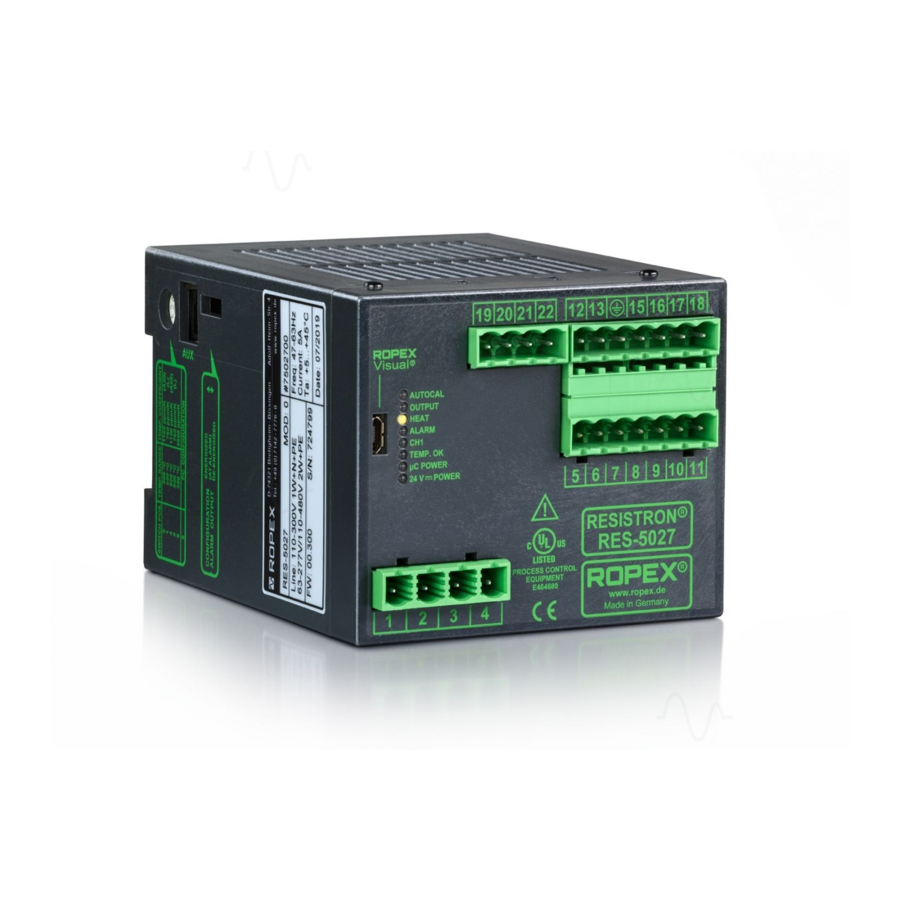
Page 20: Device Functions
EQUIPMENT 24 V POWER Lit if external 24 V power E464680 www. ROPEX (Green supply is present. Made in Germany The LEDs display additional operating statuses of the controller besides the functions in the above illustration. These are shown in detail in the following table:... -
Page 21: Temperature Setting (Setpoint Specification)
Device functions Flashes slowly (1 Hz) Flashes quickly (4 Hz) On permanently CH-1 function requested, CH-1 — CH-1 function is carried out (yellow) but function is blocked Temperature lies in the temperature monitoring band TEMP. OK — — (green) Actual value has achieved 95% of the setpoint value Voltage supply to the µC POWER... -
Page 22: Temperature Display
The connection line between controller and potentiometer must be screened. When the ROPEX precision potentiometer PD-x (PD-03 for 300 °C or PD-05 for 500 °C) is used, the set SET- POINT temperature can be set exactly with the help of the numbers in the viewing window of the fine drive button. -
Page 23: Autom. Zeroing (Autocal)
A display instrument can be attached to this output for visualisation of the heating element temperature. The ROPEX temperature display ATR-x in its overall characteristics (size, scaling, dynamic behaviour) is optimally suited for this use and can be used for this, if needed ( section 13 "How to order" on page 45). -
Page 24: Start Signal (Heat)
Device functions The AUTOCAL is activated through a 24 VDC pulse at terminals 5+13. 24 VDC RES-5027 AUTOCAL Max. 6 mA ≥ HIGH: 12 VDC AUTOCAL ≤ LOW: 2 VDC 0.1…5 s The automatic calibration process lasts about 10…15 seconds. The heating element is not additionally heated during this process. -
Page 25: Reset Signal
Device functions The START signal is activated through a 24 VDC signal to the terminals 6+13. 24 VDC RES-5027 START (HEAT) max. 6 mA ≥ HIGH: 12 VDC START (HEAT) ≤ LOW: 2 VDC During execution of the AUTOCAL function or when the RESET signal is active, activation of the START signal is not accepted. -
Page 26: Ch-1 Signal
Measurement impulse duration The length of the measurement impulses generated by the controller can be set with this parameter. For certain applications, it can be necessary to lengthen the measurement impulse beyond the standard of 1.7 ms ( ROPEX application report). -
Page 27: Automatic Phase Correction (Autocomp)
In special welding applications, it may be necessary to compensate the phase displacement between the U measurement signals ( ROPEX application report). Use of the AUTOCOMP function can be necessary here. The AUTOCOMP function must be enabled for use with the ROPEX visualisation software ( section 8.14 "USB ®... -
Page 28: Temperature Diagnosis
(terminal 17+13) goes to 0…3 °C (i.e. approx. 0 VDC). 8.10 Temperature diagnosis An additional temperature diagnosis can be activated with the ROPEX visualisation software ( section 8.14 ® "USB interface for visualisation software ROPEXvisual " on page 32). Here, the RES-5027 checks whether the ACTUAL temperature lies within a settable “good window”... -
Page 29: Temperature Reached" Or "Temperature
309, 310 is output and the alarm relay switches on. A delay time (0...9.9 s.) can also be set with the ROPEX visualisation software. After the lower tolerance band limit is exceeded, the temperature diagnosis takes place only after the parameterised delay time has expired. As a result, the temperature diagnosis can be intentionally suppressed, such as during a temperature drop caused by closing the welding jaws. - Page 30 Device functions 1. OFF 2. Active when temp. reached 3. Active when ACTUAL=SETPOINT 4. Active when ACTUAL=SETPOINT 8.11.1 Operating mode “OFF” The output signal always remains switched off. 8.11.2 “Temp. Reached” operating mode If the ACTUAL temperature of the heating element reaches more than 95% of the SETPOINT welding tempera- ture, the output signal is switched on.
-
Page 31: Heat-Up Time Monitoring
The output signal is not switched off until the next activation of the START signal or when an alarm occurs. 8.12 Heat-up time monitoring An additional heat-up time monitoring can be activated with the ROPEX visualisation software ( section 8.14 ® "USB interface for visualisation software ROPEXvisual "... -
Page 32: Booster Connection
PROCESS CONTROL EQUIPMENT E464680 www. ROPEX Made in Germany There is a separate documentation available for the ROPEX visualisation software. The software and the docu- mentation are available in the download area (search term: “Visual”). Page 32 RES-5027 Version 1... -
Page 33: Aux Interface
2…4 weeks. If the controller is switched off longer, the date and time must be set again. This must be done with the ROPEX visualisation soft- ®... -
Page 34: Error Messages
Device functions Red LED “ALARM” at the controller with three statuses: 1. Flashes quickly (4 Hz): Means that the AUTOCAL function should be performed (error no. 104…106, 211, 302, 303). 2. Flashes slowly (1 Hz): Means that the system configuration is incorrect and therefore the executed zeroing (AUTOCAL function) was not successful (... - Page 35 Device functions ® ROPEX visualisation software ( section 8.14 "USB interface for visualisation software ROPEXvisual " on page 32). The error search can thus be performed even more effectively. Evaluation of the actual value output for detection of an error message - e.g. in the higher-order controller - must be done with an adapted tolerance window to avoid incorrect evaluations.
- Page 36 Device functions Part 1 of 3: Error messages (malfunctions) NOTE: The specified error messages are output as malfunctions (actual value output emits constant error voltage; alarm LED is continuously lit; alarm relay is active). Actual value Measure of machine in Error Measure if initial start- output...
- Page 37 Device functions Part 2 of 3: Error messages (warnings) NOTE: The specified error messages are first output as warnings (actual value output switches between two values; alarm LED flashes; alarm output is not active). After activation of the START signal, it is output as a malfunction (actual value output no longer changes, see bold-italic values;...
- Page 38 Device functions Part 3 of 3: Error messages (warnings) NOTE: The specified error messages are first output as warnings (actual value output switches between two values; alarm LED flashes; alarm output is not active). After activation of the START signal, it is output as a malfunction (actual value output no longer changes, see bold-italic values;...
-
Page 39: Error Ranges And Causes
Device functions 8.20 Error ranges and causes Temperature controller HARDWARE Explanations of the possible error causes can be taken from the following table. Malfunc- Explanations Possible causes tion range Interruption of the load circuit after - Wire break, heating element break the U pickup point - Contacting at the heating element defective... -
Page 40: Factory Settings
Factory settings Malfunc- Explanations Possible causes tion range - Hardware error (replace controller) - Slide switch for alarm relay defective or not in correct posi- Internal device error tion - Network voltage missing Factory settings ® The RESISTRON temperature controller RES-5027 is configured as follows from the factory: Rotary encoder switch Heating element alloy: Alloy A20 Temperature range: 300 °C... - Page 41 Factory settings Heat-up time Heat-up time monitoring: OFF monitoring [X] Only with ROPEX visualisation software Version 1 RES-5027 Page 41...
-
Page 42: Technical Data
Besides setting through the rotary encoder switch (see below), the setting for the and temperature temperature range and temperature coefficient can be performed through the range ROPEX visualisation software ( section 8.14 "USB interface for visualisation ® software ROPEXvisual " on page 32): Temperature range: 200 °C, 300 °C, 400 °C or 500 °C... - Page 43 Technical data Analogue output 0…10 VDC, I = 5 mA, electrically separated from the heating circuit (Actual value) corresponding to 0…300 °C or 0…500 °C Terminal 17+13 Precision: ±1% plus 50 mV Reference voltage +10 VDC / ±5%, I = 5 mA output Digital logic level LOW (0 V): 0…2 VDC...
-
Page 44: Dimensions
Dimensions Connecting cable Rigid or flexible; 0.2…2.5 mm² (AWG 24…12) through pluggable terminals Type / cross-sections Pluggable terminals: Tightening torque: 0.5…0.6 Nm (Screwdriver: SZS 0.6x3.5 mm) If ferrules are used, they must be crimped in accordance with DIN 46228 and IEC/EN 60947-1. Otherwise, correct electrical contact in the terminals is not guaranteed. -
Page 45: How To Order
50520: Continuous curr. 50 A, 520 VAC, art. no. 885509 (with UL and CSA certification) Impulse transformer For design and order specifications, see ROPEX applica- tion report Design in accordance with EN 61558 Available with UL certifications and thermal switch, if nec- essary. - Page 46 Booster B- . . . 075415: Impulse loaded 75 A, 415 VAC, art. no. 885302 100400: Impulse loaded 100 A, 400 VAC, art. no. 885304 Lines For design and order specifications, see ROPEX applica- tion report Additional accessories “Accessories” brochure Page 46...
-
Page 47: Index
Index Index Numbers 24VDC supply Factory settings Functional principle Fuse Actual value output Alarm output Alarm relay HEAT Alloy Heating element type Ambient conditions Heat-up time monitoring Ambient temperature High altitude How to order Analogue input Humidity Analogue output Application Report AUTOCAL Impulse transformer AUTOCOMP... - Page 48 Index Temperature setting Thermal impulse process Setpoint potentiometer Time Setpoint specification Time stamp Setup stipulations Transformer START signal Transportation System diagnosis System monitoring UL file USB interface Technical data Temperature coefficient Temperature diagnosis Temperature display Visualisation software “Temperature OK” signal Temperature range “Temperature reached”...
Need help?
Do you have a question about the RESISTRON RES-5027 and is the answer not in the manual?
Questions and answers