Table of Contents
Advertisement
Quick Links
RESISTRON
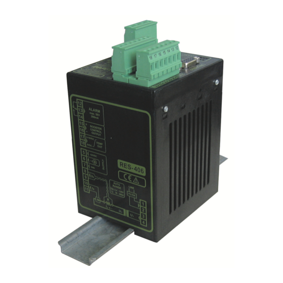
RES-406
Operating
instructions
Important features
•
Complete control via PROFIBUS-DP interface
•
Automatic zero calibration (AUTOCAL)
•
Automatic optimization (AUTOTUNE)
•
Automatic configuration of the secondary voltage and current ranges
(AUTORANGE, as of February 2006)
•
Automatic phase angle compensation (AUTOCOMP, as of February 2006)
•
Automatic frequency adjustment
•
Booster connection as standard
•
0...10VDC analog output for ACTUAL temperature
•
Alarm function with fault diagnosis
•
Heatsealing band alloy and temperature range selectable
ROPEX Industrie-Elektronik GmbH
Adolf-Heim-Str. 4
74321 Bietigheim-Bissingen (Germany)
Tel.: +49 (0)7142-7776-0
Fax: +49 (0)7142-7776-211
E-Mail:
info@ropex.de
Internet:
https://ropex.de
Data subject to change
Advertisement
Table of Contents

Related Manuals for Ropex RESISTRON RES-406


Summary of Contents for Ropex RESISTRON RES-406
- Page 1 Booster connection as standard • 0…10VDC analog output for ACTUAL temperature • Alarm function with fault diagnosis • Heatsealing band alloy and temperature range selectable ROPEX Industrie-Elektronik GmbH Tel.: +49 (0)7142-7776-0 E-Mail: info@ropex.de Adolf-Heim-Str. 4 Fax: +49 (0)7142-7776-211 Internet: https://ropex.de...
-
Page 2: Table Of Contents
Contents General information ....3 Controller functions ....22 Copyright . -
Page 3: General Information
The temperature coefficient must be taken from the ROPEX application report and must be set accordingly. The use of incorrect alloys with a too low temperature coefficient and incorrect coding of the ®... -
Page 4: Impulse Transformer
The use of an original ROPEX line filter is mandatory in order to comply with the directives mentioned in section "DECLARATION OF CONFORMITY" on page 6. This device must be installed and connected according to the instructions contained in section "Power supply"... -
Page 5: Disposal
General information Disposal This device is subject to Directive 2012/19/EU concerning the reduction of the increasing amount of waste electrical and electronic equipment and the disposal of such waste in an environmentally sound way. To guarantee proper disposal and / or the recover of reusable material, please take the device to a designated municipal collection point and observe local regulations. - Page 6 We also wish to point out that the transformer which is used must be designed in accordance with VDE 0551/EN 61558 or UL 5058 for safety reasons. July 12, 2020 J. Kühner (CEO) ROPEX Industrie-Elektronik GmbH Adolf-Heim-Str. 4 74321 Bietigheim-Bissingen (Germany) Page 6...
-
Page 7: Application
Application Application ® This RESISTRON temperature controller is an integral part of the "Series 400", the outstanding feature of which is its microprocessor technology. All RESISTRON temperature controllers are used to control the temperature of heating elements (heatsealing bands, beaded bands, cutting wires, heatsealing blades, solder elements etc.), as required in a variety of heatsealing processes. -
Page 8: Installation
An overcurrent protective device (e.g. a fuse) must be fitted when the controller is installed. The minimum pos- sible specification for this device must be entered in the ROPEX Application Report based on the calculated currents. If a larger overcurrent protective device is fitted, you must match the current carrying capacity of the other components accordingly (e.g. - Page 9 Installation ® 5. Connect the RESISTRON temperature controller to the PROFIBUS master using a cable according to IEC 61158. Check the tightness of all the system connections, including the terminals for the impulse trans- former windings. 6. Make sure that the wiring conforms to the relevant national and international installation regulations. Version 1 RES-406 Page 9...
-
Page 10: Installation Steps
Installation Installation steps Use heatseal bands with suitable temperature coefficient Heatseal element push-on with coppered ends connectors Heatsealing band R= f (T) No additional Connect U measuring resistance wires directly to in secondary heatsealing band ends Note circuit number Sufficient wire of turns Twisted cross-section... -
Page 11: Power Supply
Connect core to ground. Use transformers with a one section bobbin. The power, duty cycle and voltage values must be deter- mined individually according to the application ( ROPEX SEC. Application Report and "Accessories" leaflet for impulse transformers). -
Page 12: Line Filter
ROPEX line filters are specially optimized for use in RESISTRON control loops. Providing that they are installed and wired correctly, they guarantee compliance with the EMC limit values. You can find the exact specification of the line filter in the ROPEX Application Report calculated for your particular heatsealing application. - Page 13 Installation 5.5.1 PEX-W4 terminal wires terminal block Snap-on for DIN-rail 35 x 7.5 mm or 35 x 15 mm (DIN EN 50022) 5.5.2 PEX-W5 Mounting on DIN-rail 35 x 7.5 mm or 35 x 15 mm (DIN EN 50022). Version 1 RES-406 Page 13...
-
Page 14: Wiring Diagram (Standard)
Installation Wiring diagram (standard) PROFIBUS-PLUG Line filter LF-xx480 SUB-D / 9-POLE RES-406 LINE Shield (GND pwr. supply) M24 PROFIBUS DGND controller electrically (+5V) VP isolated (+24V pwr. supply) P24 prim. Impulse transformer +24VDC sec. POWER SUPPLY Heat- sealing band twisted ALARM OUTPUT max. -
Page 15: Wiring Diagram With Booster Connection
Installation Wiring diagram with booster connection PROFIBUS-PLUG Line filter LF-xx480 SUB-D / 9-POLE RES-406 LINE Shield Booster (GND pwr. supply) M24 PROFIBUS DGND controller electrically (+5V) VP isolated (+24V pwr. supply) P24 prim. Impulse transformer +24VDC sec. POWER SUPPLY Heat- sealing band twisted... -
Page 16: Startup And Operation
Set the DIP switches for matching the secondary voltage U and the secondary current I to the correct position for your application. You can find the exact configuration of the DIP switches in the ROPEX Application Report calculated for your par- ticular application. Page 16 RES-406... - Page 17 If the switch is set to "9" (as of February 2006), more temperature ranges and alloys can be selected by means of the ROPEX visualization software ( see section 7.11 "Diagnostic interface/visualization software (as of February 2006)" on page 47).
-
Page 18: Replacing And "Burning In" The Heatsealing Band
If the "Alarm relay deenergized by alarm/PC CONFIGURATION" position is selected (as of February 2006), the behavior of the alarm output can be configured in more detail by means of the ROPEX visualization software ( see section 7.11 "Diagnostic interface/visualization software (as of February 2006)" on page 47). -
Page 19: Startup Procedure
3. In the case of controllers manufactured up to January 2006, the settings of the DIP switches on the controller are indicated in the ROPEX Application Report and depend on the heatsealing band that is used. The settings of the coding switches on the controller depend on the required station address in the PROFIBUS network (... - Page 20 If the zero point has not been calibrated successfully, the "AL" bit (alarm active) is set and the red "ALARM" LED blinks slowly (1Hz). In this case the controller configuration is incorrect ( section 6.2 "Controller config- uration" on page 16 and ROPEX Application Report). Repeat the calibration after the controller has been con- figured correctly.
- Page 21 Startup and operation PROFIBUS protocol (set point) and set the "ST" bit. The "RA" bit (controller active) is then activated and the "HEAT" LED lights up. The heating and control process can be observed at the actual value output: The controller is functioning correctly if the temperature (which corresponds to the signal change at the analog output or the actual value in the PROFIBUS protocol) has a harmonious motion, in other words it must not jump abruptly, fluctuate or deviate temporarily in the wrong direction.
-
Page 22: Controller Functions
RESISTRON (yellow LED) AUTOCAL process. RES- 406 Temperature controller 24V SUPPLY Lit if external 24VDC power ROPEX (green LED) supply is present. Tel:+49(0)7142-7776-0 BUS PWR OK Lit if internal 5VDC power (green LED) supply for Profibus interface is Made in Germany µC PWR OK... - Page 23 Yellow LED, lit during heating phase. RESISTRON Red LED, lights up or blinks to indicate alarm. μP-Controller ROPEX Green LED, remains lit as long as PROFIBUS data is beeing exchanged with master. INDUSTRIE - ELEKTRONIK In addition to the functions shown in the diagram above, various controller operating states are indicated by the LEDs.
-
Page 24: Profibus Communication "Up To Jan
German (.GSG) and English (.GSD or .GSE) on a diskette. They can also be requested by E-Mail (support@ropex.de) or they can be downloaded from our Homepage (www.ropex.de). After the required device master file has been linked into the configuring tool, you must select one of the two com- munication modules ("compact"... - Page 25 Controller functions If you want to use all features of the controller make sure that the appropriate version of the device master file is used. Since production date 06.02 the required device master file version is printed on the housing of the temperature controller. required GSD version Version 1 RES-406...
-
Page 26: Profibus Protocol
Controller functions PROFIBUS protocol The PROFIBUS protocol can be configured either as "compact" (16bits for input data and 16bits for output data) or as "extended" (2x16bits for input data and 2x16bits for output data). The protocol is determined at the config- uring stage by selecting a module ("compact"... - Page 27 Controller functions 7.4.3 "Extended" protocol with 4-Bit error code The extended protocol transfers 2x16bits. The 2x16-bit input data contains the set point in word and the con- trol functions in word : Spare Set point / AC temperature Name: Bit no.: ...
-
Page 28: Input Data
Controller functions The 2x16-bit output data contains the actual value in word and the error code and status information in word : Actual value (signed) Name: Bit no.: Error code Status information Name: Bit no.: Input data The term "input data"... - Page 29 Controller functions Reasons for disabled AUTOCAL function: 1. The AUTOCAL function cannot be activated until 10 seconds after the controller is switched on. During this time the controller reports "AUTOCAL disabled" ("AG" bit = 1) in the output data. 2. The AUTOCAL function is not activated if the heatsealing band is cooling down at a rate of more than 0.1K/ sec.
-
Page 30: Output Data
Controller functions If a contactor Kb is used to deactivate the control loop ( section 5.3 "Power supply" on page 11), it must be reliably energized again 200ms at the latest after the "RS" bit is reset (note the contactor switching and delay times). - Page 31 Controller functions 7.6.5 Temperature OK (TO) The RES-406 checks whether the actual temperature is within a settable tolerance band ("OK" window) on either side of the set temperature. The lower ( Δϑ ) and upper ( Δϑ ) limits of the tolerance band can be lower upper changed independently of one another by means of the parameter data (...
- Page 32 For controllers with software revision 100, 101 and 102 the configuration for the „TO“ bit can be set via the ROPEX visualization software. As of software revision 103 the configuration for the „TO“ bit is set in the PROFIBUS parameter data (or the DPV1 protocoll extension). A configuration with the ROPEX visual- ization software is no more possible.
- Page 33 Controller functions 7.6.8 Actual value If you are using the compact protocol, the actual value itself is always positive. The sign bit (VZ) then indicates whether the amount of the actual value is positive or negative. If an alarm is signaled, the actual value contains the error code.
-
Page 34: Parameter Data
Controller functions In addition to the error codes, the PROFIBUS diagnostics function also sends error messages to the PROFIBUS master. The error messages corresponding to each error code are already stored in the device master file (GSD), so that they automatically appear in plain text on the PROFIBUS master whenever the device diagnosis for the RES-406 is interrogated there. - Page 35 Controller functions fault Possible Function value values Temperature 1100 400…4000 coefficient (as of Feb. 2006 and GSD Version v2.0) Temperature range 300° 200, 300, (as of Feb. 2006 and 400, 500°C GSD Version v2.0) Maximum 300° 200…500° temperature (as of Feb. 2006 and GSD Version v2.0) Temperature deactivated,...
- Page 36 The settings for a temperature coefficient of 780ppm (values 1 and 5) are only available on control- lers manufactured as of October 2003. The setting „ROPEX visualization software“ (value 9) is available on controllers manufactured as of March 2007 and supplied with GSD Version v2.0.
- Page 37 Controller functions As of GSD Version v1.6, the calibration temperature can be activated for setting by means of the input data by selecting the value "-1" in the parameter data. The calibration temperature can then be specified via the "Set point/ AC temperature input data (...
- Page 38 It may be necessary to compensate the phase angle displacement between the U and I measuring signals for special heatsealing applications ( ROPEX Application Report). The "AUTOCOMP" function is provided for this purpose. The follwing settings are possibe: 1. „off“ (Factory setting) The „AUTOCOMP“...
- Page 39 Controller functions The "OUTPUT" LED blinks repeatedly when the "AUTOCOMP" function is executed and the actual value output (terminals 17+14) is set to 0…3°C (i.e. app. 0 VDC). 3. „AUTO“ (as of software revision 105) With this setting the „AUTOCOMP“ function is activated automatically after the "AUTOCAL" function has been successfully executed.
- Page 40 The lower and upper tolerance band limits cannot be set in the ROPEX visualization software. The same limits apply as for the TO bit. They can only be set by means of the PROIBUS parameter data (...
- Page 41 Hold mode affects the digital value of the real temperature in the PROFIBUS communiction and the numeric temperature display in the ROPEX visualization software only. The output of the real tem- perature on the actual value output and the data record in the graphics window of the ROPEX visualization software is not affected.
-
Page 42: Dpv1 Protocol Extension (As Of Gsd Version V2.0)
Controller functions The various hold modes are shown below: „ST“ bit ACTUAL temp. ACTUAL indication Hold off Hold on Hold Hold Hold 2 s Hold Hold End of heating phase The "Holde mode" function must be activated by means of the PROFIBUS parameter data (... - Page 43 Controller functions 7.8.3 DPV1 parameter data The basic controller settings and functions can be set with the parameter data in the device master file (GSD file, section 7.7 "Parameter data" on page 34). Some PLC systems only allow you to change the settings in the GSD file when you create a new project. The settings cannot be changed while the machine or system is operating.
- Page 44 Controller functions Slot Index Parameter Value range Temperatur range 0: 200°C 1: 300°C 2: 400°C 3: 500°C Maximum temperature [°C] 200…500 (300) Temperature diagnosis 0: deactivated 1: activated Temperature diagnosis delay time 0…99 (0) [0.1s steps] Heatup timeout [0.1s steps] 0…999 (0) AUTOCOMP 0: off...
-
Page 45: Temperature Indication
Controller functions Temperature indication (actual value output) The RES-406 supplies an analog 0…10VDC signal, which is proportional to the real ACTUAL temperature, at ter- minals 17+18. RES-406 max. 5mA Actual value output 0...10VDC 0...10VDC Temperature meter e.g. ATR-3 Voltage values: 0VDC 0°C ... - Page 46 An indicating instrument can be connected to this output in order to visualize the temperature of the heatsealing band. The characteristics of the ROPEX ATR-x temperature meter (size, scaling, dynamic response) are ideally suited to this application and this instrument should therefore always be used ( section 12 "How to order" on page 60).
-
Page 47: Booster Connection
The number of operating hours since the controller was first delivered is stored internally. This counter works with a resolution of six minutes. It can only be displayed and not reset. It can only be displayed in the ROPEX visuali- zation software (... -
Page 48: Log Function
This log can only be displayed and not deleted. It can only be displayed in the ROPEX visualization software ( section 7.11 "Diagnostic interface/visualization software (as of February 2006)" on page 47). -
Page 49: Error Messages
February 2006. The error messages are differentiated even more finely in the controller. The 3-digit error codes described in brakets below can be displayed with the ROPEX visualization software ( section 7.11 "Diagnostic interface/visualization software (as of February 2006)" on page 47) to facilitate troubleshooting. - Page 50 Controller functions Part 1 of 3: Error messages as of February 2006 (faults) NOTE: The error messages shown here are output as faults (constant error voltage at actual value output, alarm LED lit continuously, alarm relay energized). Act. val. Action if machine Error output Action if machine...
- Page 51 Controller functions Part 2 of 3: Error messages as of February 2006 (warnings) NOTE: The specified error messages are initially output as warnings (actual value output jumps back and forth between two values, alarm LED blinks, alarm relay de-energized). When the "START" signal is activated, the warning changes to a fault (actual value output no longer jumps back and forth, see bold italic values, alarm LED lit continuously, alarm relay energized).
- Page 52 Controller functions Part 3 of 3: Error messages as of February 2006 (warnings) NOTE: The specified error messages are initially output as warnings (actual value output jumps back and forth between two values, alarm LED blinks, alarm relay de-energized). When the "START" signal is activated, the warning changes to a fault (actual value output no longer jumps back and forth, see bold italic values, alarm LED lit continuously, alarm relay energized).
- Page 53 Controller functions Version 1 RES-406 Page 53...
-
Page 54: Fault Areas And Causes
Controller functions 7.17 Fault areas and causes Temperature controller HARDWARE The table below explains the possible fault causes. Fault area Explanation Possible causes Load circuit interrupted after U - Wire break, heatsealing band break - Contact to heatsealing band is defective pickoff point ... -
Page 55: Factory Settings
Factory settings Fault area Explanation Possible causes - Up to Jan. 2006: DIP switches 4 + 5 configured incorrectly range) signal incorrect - As of Feb. 2006: I outside permissible range from 30…500A Turns through current transformer - Check number of turns (two or more turns required for incorrect currents <... - Page 56 Factory settings Rotary coding Station address = 01 switches x 10 station address Top of housing Automatic phase AUTOCOMP: off angle compensation (AUTOCOMP) Temperature Temperature diagnosis: deactivated diagnosis Heatup timeout Heatup timeout: deactivated [X] As of February 2006 and GSD Version v2.0: Setting by means of the PROFIBUS parameter data or the DPV1 protocol extension.
-
Page 57: Technical Data
The temperature range and temperature coefficient settings can also be specified range by means of the ROPEX visualization software ( section 7.11 "Diagnostic inter- face/visualization software (as of February 2006)" on page 47) in addition to the rotary coding switch (see below): Temperature range: 200°C, 300°C, 400°C or 500°C... - Page 58 Technical data Analog output 0…10V DC, Imax = 5mA (actual value) Equivalent to 0…300°C or 0…500°C Terminals 17+18 Accuracy: ±1% add. 50mV Alarm relay = 30V (DC/AC), I = 0.2A, changeover contact, potential-free Terminals 12, 13, 14 Maximum load = 5A (duty cycle = 100%) (primary current of = 25A (duty cycle = 20%) impulse...
-
Page 59: Dimensions
Dimensions Dimensions 75.0 90.0 Modifications (MODs) ® Owing to its universal design, the RESISTRON temperature controller RES-406 is suitable for a very wide range of heatsealing applications. ® One modification (MOD) is available for the RESISTRON temperature controller RES-406 for implementing spe- cial applications. -
Page 60: How To Order
Line filter LF- . . 480 06: Continuous current 6A, 480VAC, P/N 885500 35: Continuous current 35A, 480VAC, P/N 885506 Impulse transformer See ROPEX Application Report for design and ordering information Communiction interface CI-USB-1 P/N 885650 Temp. meter ATR- . -
Page 61: Index
Index Index Numbers Extended controller diagnosis External switching amplifier 24VDC-Supply voltage Factory settings "AA" bit Fault areas "AC" bit Fault diagnosis Actual value Fuse Actual value output "AG" bit "AL" bit Alarm Alarm output Alarm relay Alloy Heatsealing band type Ambient temperature Heatup timeout Application... - Page 62 Index PROFIBUS-DP interface Protocol Compact, 10-Bit error code "TE" bit Compact, 4-Bit error code Temperature coefficient Extended, 10-Bit error code Temperature control Extended, 4-Bit error code Temperature diagnosis Temperature indication Temperature meter Temperature OK "RA" bit Temperature range Replacing the heatsealing band Temperature reached Reset "TO"...
Need help?
Do you have a question about the RESISTRON RES-406 and is the answer not in the manual?
Questions and answers