Table of Contents
Advertisement
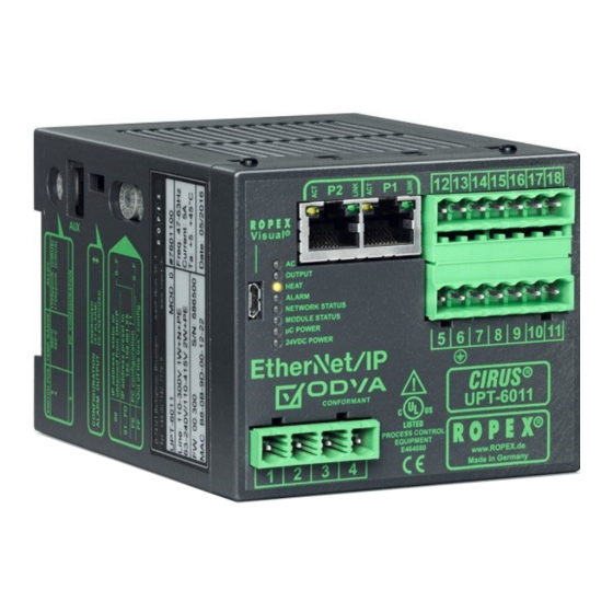
CIRUS
UPT-6011
Operating
instructions
®
The CIRUS
Temperature Controller UPT-6011 is a key component in an ULTRA-PULSE system,
because it is responsible for all heat management functions, i.e. controlling the temperature of
the heating element.
Important features
•
Complete control via EtherNet/IP
•
Automatic zeroing (AUTOCAL)
•
Automatic configuration of the secondary voltage and current range (AUTORANGE)
•
Automatic frequency adaptation
•
Booster output standard
•
Analogue output 0...10 VDC for ACTUAL temperature
•
Alarm function with error diagnosis
•
Heating element alloy and temperature range can be selected
•
Cooling system monitored
•
Wide voltage range for the use of 110...480 V
•
Eight channels for administration of various calibration values
•
Micro-USB interface for ROPEXvisual
•
cULus approval
1. Standard: 415 V, optional and on request: 480 V
ROPEX Industrie-Elektronik GmbH
Adolf-Heim-Str. 4
74321 Bietigheim-Bissingen (Germany)
TM
interface (2 x RJ-45)
1
(as from 02/2021)
®
Tel.: +49 (0)7142-7776-0
Fax: +49 (0)7142-7776-211
E-Mail:
info@ropex.de
Internet:
https://ropex.de
Data subject to change
Advertisement
Table of Contents

Subscribe to Our Youtube Channel
Related Manuals for Ropex CIRUS UPT-6011


Summary of Contents for Ropex CIRUS UPT-6011
- Page 1 Eight channels for administration of various calibration values ® • Micro-USB interface for ROPEXvisual • cULus approval 1. Standard: 415 V, optional and on request: 480 V ROPEX Industrie-Elektronik GmbH Tel.: +49 (0)7142-7776-0 E-Mail: info@ropex.de Adolf-Heim-Str. 4 Fax: +49 (0)7142-7776-211 Internet: https://ropex.de...
-
Page 2: Table Of Contents
Contents Revision list ......3 Device functions ....22 LEDs and controls . -
Page 3: Revision List
Version Change • Creation of documentation • Change to one column layout • ROPEX logo changed • Covering page with important features • Additions in general information section 2 "General information" on page 3 • Addition in Communication protocol: Status bit measurement interruption ... -
Page 4: Copyright
® The current transformer supplied with the CIRUS Temperature Controller is an integral part of the control system. Only the original ROPEX PEX-W4 or PEX-W5 current transformer may be used. Other transformers may cause the equipment to malfunction. ® The current transformer may only be operated if it is correctly connected to the CIRUS Temperature Controller (see section "Startup and operation"). -
Page 5: Line Filter
The use of an original ROPEX line filter is mandatory in order to comply with the standards and provisions mentioned in section 2.7 "Standards / CE marking" on page 5. This device must be installed and connected according to the instructions contained in section "Power supply"... -
Page 6: Maintenance
General information Maintenance The controller requires no special maintenance. Regular inspection and / or tightening of the terminals – including the terminals for the winding connections on the impulse transformer – is recommended. Dust deposits on the con- troller can be removed with dry compressed air. Dust deposits and dirt from liquids result in a loss of function. -
Page 7: Declaration Of Conformity
We also wish to point out that the transformer which is used must be designed in accordance with VDE 0551/EN 61558 or UL 5058 for safety reasons. July 12, 2020 J. Kühner (CEO) ROPEX Industrie-Elektronik GmbH Adolf-Heim-Str. 4 74321 Bietigheim-Bissingen (Germany) Page 7... -
Page 8: Application
Application Application ® This CIRUS Temperature Controller is an integral part of the "series 6000". Its sole purpose is to control the tem- perature of CIRUS/UPT heating elements.The main application area is sealing or cutting of thermoplastics using the thermal impulse process. The most common application areas are: •... -
Page 9: Functional Principle
Exact compliance with the installation and wiring instructions is essential. The system has been evolved and optimized by ROPEX GmbH in an intensive development process. Users who follow our technical recommendations will profit from the unique functionality of this technology, which reduces the customer's effort for installation, commissioning and maintenance to a minimum. -
Page 10: Mounting And Installation
5. Ensure an adequate cable cross-section for the primary and secondary circuits (Ä Application Report). 6. Use only ROPEX impulse transformers or transformers approved by ROPEX. Please note the power, duty cycle, and primary and secondary voltages (Ä Application Report). - Page 11 If one such device is not adequate for the heatsealing application, two separate overcurrent protective devices should be provided – one for the controller and one for the application ( ROPEX Application Report). The overcurrent protective device must be located directly adjacent to the controller.
-
Page 12: Power Supply
Connect core to ground. Use transformers with a one section bobbin. The power, duty cycle and voltage values must be deter- mined individually according to the application ( ROPEX SEC. Application Report and "Accessories" leaflet for impulse transformers). -
Page 13: Line Filter
ROPEX line filters are specially optimized for use in CIRUS control loops. Providing that they are installed and wired correctly, they guarantee compliance with the EMC limit values. You can find the exact specification of the line filter in the ROPEX Application Report calculated for your particular heatsealing application. - Page 14 Mounting and installation 6.5.1 PEX-W4 terminal wires terminal block Snap-on for DIN-rail 35 x 7,5 mm or 35 x 15 mm (EN 60715) 6.5.2 PEX-W5 Mounting on DIN-rail 35 x 7.5 mm or 35 x 15 mm (EN 50022). If the high-current wire cannot be routed through the opening provided, an HCB-1 high-current rail must be used. Version 5 UPT-6011 Page 14...
-
Page 15: Wiring Diagram (Standard)
Mounting and installation Wiring diagram (standard) Line filter UPT-6011 LINE Ethernet PORT 1 (RJ45) BOOSTER OUTPUT Ethernet module prim. Shield Impulse Ethernet transformer PORT 2 (RJ45) (for assignment sec. see PORT 1) Ground Must be grounded Heating externally to element prevent twisted electrostatic... -
Page 16: Wiring Diagram With Booster Connection
Mounting and installation Wiring diagram with booster connection Line filter UPT-6011 LINE Ethernet PORT 1 (RJ45) Booster twisted Ethernet Max. length 1m module prim. Shield Impulse Ethernet transformer PORT 2 (RJ45) (for assignment sec. see PORT 1) Ground Must be grounded Heating externally to element... -
Page 17: Startup And Operation
( section 8.19 "Error messages" on page 67). If the secondary current I is less than 30 A, the secondary high-current wire must be laid twice (or several times) through the PEX-W4 or PEX-W5 current transformer ( ROPEX Application Report). Page 17 UPT-6011... - Page 18 The setting of the rotary coding switch for the temperature range and alloy can be overwritten with the parameter data ( section 8.7 "Parameter object (class: 0x0F)" on page 31). If the switch is set to "9", more temperature ranges and alloys can be selected in the ROPEX visualization software ®...
-
Page 19: Heating Element
(factory setting) If the switch is set to "Alarm relay de-energized at alarm / PC CONFIGURATION", you can select more alarm output configurations in the ROPEX visualization software ( section 8.12 "USB interface for visualization soft- ® ware ROPEXvisual "... -
Page 20: Commissioning Rules
(1 Hz). In this case the controller configuration is incorrect ( section 7.2 "Device configuration" on page 17, ROPEX Application Report). Repeat the calibration after correcting the controller configuration. 9. After the zero point has been successfully calibrated, specify a defined temperature by means of the EtherNet/ protocol (set point) and set the ST bit. - Page 21 Startup and operation abruptly, fluctuate, or temporarily deviate in the wrong direction. This kind of behaviour would indicate that the measurement cable was laid incorrectly. If an error code is displayed, proceed as described in section 8.19 "Error messages" on page 67. 10.Optimize the heating and control process either by adjusting the correction factor Co in the parameter data (EDS file) or using the parameter object (...
-
Page 22: Device Functions
E QUI P M E NT 24 V POWER Lit if external 24 VDC power E 464680 www. ROPEX (green LED) supply is present. Made in Germany In addition to the functions shown above, the LEDs also indicate various controller operating states. These states... -
Page 23: Ethernet/Ip Tm Communication
ROPEX_UPT-6011_V2_5.eds file of the UPT-6011 contains all essential controller information for the configura- tion, e.g. the I/O data description, parameter descriptions etc. The device description files and the associated image files (.BMP and .ICO) can be requested by e-mail (support@ropex.de) or downloaded from our website (https://ropex.de). -
Page 24: Communication Protocol
Device functions If the controller already has an IP address, the device description file can also be downloaded from the integrated web server. Alternatively, you can download it from the controller via the file object using CIP services. After linking the required device description file into the configuring tool, you must assign an IP address to the con- troller. - Page 25 Device functions 8.5.1 Automatic zero calibration AUTOCAL (AC) Owing to the automatic zero calibration (AUTOCAL) function, there is no need to adjust the zero point manually on the controller. This function adjusts the controller to the current and voltage signals present in the system and calibrates it to the value which is predefined in the parameter data (...
- Page 26 Device functions The base resistance of the heatsealing element increases during the operation determined by the design continuously. To prevent measurement errors of the ACTUAL temperature the AUTOCAL function must be performed approximately every 100000 sealing cycles. 8.5.2 Start (ST) When the START bit is set (ST bit = 1), the controller’s internal set / actual comparison is enabled and the heating element is heated to the SET temperature.
-
Page 27: Output Data
Device functions This reference value serves to calculate the deviation from the calibration value for all subsequent calibrations (ini- tiated with the AC bit). This deviation helps you assess aging of the heating element. The deviation from the calibration value is queried by means of the parameter object. 8.5.6 Channel selection (CH0…CH2) The temperature controller has separate memories for up to eight calibration data records. - Page 28 Device functions 8.6.4 Warning active (WA) This bit can be set in addition to the AL bit. If the WA bit is set, a warning is output to indicate the current fault. In this case, the alarm relay is not active. 8.6.5 Temperature achieved (TE) The TE bit is set if the actual temperature exceeds 95% of the set temperature.
- Page 29 Device functions a.) Temperature not ok b.) Temperature ok Actual value Actual value Set+ Set+ high high Setpoint Setpoint Set+ Set+ Time Time ST bit ST bit Time Time TO bit TO bit Time Time ± The limits of the tolerance band are adjustable up to a maximum of 99 K.
- Page 30 Device functions Behaviour of the temperature controller In order to be able to assess the behaviour of the temperature controller, you will find examples of the statuses of the voltage supply and the resulting statuses of the controller in the table. The table represents a chronological sequence.
-
Page 31: Parameter Object (Class: 0X0F)
Device functions 1. If the alarm is acknowledged, but the line voltage is still switched off, error code 901 will immediately be displayed. If the line voltage is then switched on and the alarm is acknowledged once again, the temper- ature controller goes into control mode. - Page 32 Device functions The parameter object has the following structure: Attri- Data Instanc Default bute Name Value range value type UINT Revision (class) UINT Max. instance UINT Max. class attribute UINT Max. instance attribute UINT Parameter class description UINT Configuration assembly USINT Temperature range / alloy 0, 4, 9, 10, 11...
- Page 33 Device functions Attri- Data Instanc Default bute Name Value range value type SINT Calibration temperature 20 °C -1 (= variable), 0…40 °C USINT Link path length EPATH Link path 20 0F 24 04 30 01 WORD Descriptor 0x0000 USINT Data type 0xC2 USINT Data length...
- Page 34 Device functions Attri- Data Instanc Default bute Name Value range value type BOOL Data format Little Endian, Little Endian, Intel Intel (0) (0), Big Endian, Motorola USINT Link path length EPATH Link path 20 0F 24 07 30 01 WORD Descriptor 0x0000 USINT...
- Page 35 Device functions Attri- Data Instanc Default bute Name Value range value type USINT Temperature range 1 (300 °C) 0 (200 °C), 1 (300 °C), 2 (400 °C), 3 (500 °C) USINT Link path length EPATH Link path 20 0F 24 0B 30 01 WORD Descriptor 0x0000...
- Page 36 Device functions Attri- Data Instanc Default bute Name Value range value type UINT Heatup timeout 0…999 (10 ms steps) (0…9.99 s) USINT Link path length EPATH Link path 20 0F 24 0F 30 01 WORD Descriptor 0x0004 (scaling supported) USINT Data type 0xC7 USINT...
- Page 37 Device functions Attri- Data Instanc Default bute Name Value range value type SINT Calibration temperature, channel 1 20 °C -1 (= variable), 0…40 °C USINT Link path length EPATH Link path 20 0F 24 12 30 01 WORD Descriptor 0x0000 USINT Data type 0xC2...
- Page 38 Device functions Attri- Data Instanc Default bute Name Value range value type UINT Temperature coefficient, channel 2 1700 ppm/K 400…4000 ppm/K USINT Link path length EPATH Link path 20 0F 24 17 30 01 WORD Descriptor 0x0000 USINT Data type 0xC7 USINT Data length...
- Page 39 Device functions Attri- Data Instanc Default bute Name Value range value type UINT Correction factor, channel 4 25…200% USINT Link path length EPATH Link path 20 0F 24 1C 30 01 WORD Descriptor 0x0000 USINT Data type 0xC7 USINT Data length UINT Temperature coefficient, channel 4 1700 ppm/K...
- Page 40 Device functions Attri- Data Instanc Default bute Name Value range value type SINT Calibration temperature, channel 6 20 °C -1 (= variable), 0…40 °C USINT Link path length EPATH Link path 20 0F 24 21 30 01 WORD Descriptor 0x0000 USINT Data type 0xC2...
- Page 41 Device functions Attri- Data Instanc Default bute Name Value range value type UINT Temperature coefficient, channel 7 1700 ppm/K 400…4000 ppm/K USINT Link path length EPATH Link path 20 0F 24 26 30 01 WORD Descriptor 0x0000 USINT Data type 0xC7 USINT Data length...
- Page 42 Device functions Attri- Data Instanc Default bute Name Value range value type UDINT Cycle counter (clearable) 0…99999999 USINT Link path length EPATH Link path 20 0F 24 2B 30 01 WORD Descriptor 0x0000 USINT Data type 0xC8 USINT Data length UDINT Cycle counter, channel 0 0…99999999...
- Page 43 Device functions Attri- Data Instanc Default bute Name Value range value type UDINT Cycle counter, channel 4 0…99999999 USINT Link path length EPATH Link path 20 0F 24 30 30 01 WORD Descriptor 0x0000 USINT Data type 0xC8 USINT Data length UDINT Cycle counter, channel 5 0…99999999...
- Page 44 Device functions Attri- Data Instanc Default bute Name Value range value type Device temperature -60…190 °C USINT Link path length EPATH Link path 20 0F 24 35 30 01 WORD Descriptor 0x0010 USINT Data type 0xC3 USINT Data length Calibration deviation, channel 0 -100.00…100.00% USINT Link path length...
- Page 45 Device functions Attri- Data Instanc Default bute Name Value range value type Calibration deviation, channel 4 -100.00…100.00% USINT Link path length EPATH Link path 20 0F 24 3A30 01 WORD Descriptor 0x0010 USINT Data type 0xC3 USINT Data length Calibration deviation, channel 5 -100.00…100.00% USINT Link path length...
- Page 46 Device functions Attri- Data Instanc Default bute Name Value range value type UINT Calibration resistance, channel 0 0…65535 (in 0.1 m (0…6553.5 m USINT Link path length EPATH Link path 20 0F 24 3F 30 01 WORD Descriptor 0x0014 (scaling supported) USINT...
- Page 47 Device functions Attri- Data Instanc Default bute Name Value range value type UINT Calibration resistance, channel 3 0…65535 (in 0.1 m (0…6553.5 m USINT Link path length EPATH Link path 20 0F 24 42 30 01 WORD Descriptor 0x0014 (scaling supported) USINT...
- Page 48 Device functions Attri- Data Instanc Default bute Name Value range value type UINT Calibration resistance, channel 6 0…65535 (in 0.1 m (0…6553.5 m USINT Link path length EPATH Link path 20 0F 24 45 30 01 WORD Descriptor 0x0014 (scaling supported) USINT...
- Page 49 Device functions Attri- Data Instanc Default bute Name Value range value type UINT Initial calibration resistance, 0…65535 channel 1 (in 0.1 m (0…6553.5 m USINT Link path length EPATH Link path 20 0F 24 48 30 01 WORD Descriptor 0x0014 (scaling supported)
- Page 50 Device functions Attri- Data Instanc Default bute Name Value range value type UINT Initial calibration resistance, 0…65535 channel 4 (in 0.1 m (0…6553.5 m USINT Link path length EPATH Link path 20 0F 24 4B 30 01 WORD Descriptor 0x0014 (scaling supported)
- Page 51 Device functions Attri- Data Instanc Default bute Name Value range value type UINT Initial calibration resistance, 0…65535 channel 7 (in 0.1 m (0…6553.5 m USINT Link path length EPATH Link path 20 0F 24 4E 30 01 WORD Descriptor 0x0014 (scaling supported)
- Page 52 Device functions Attri- Data Instanc Default bute Name Value range value type UINT 400…4000 ppm/K Calculated temperature coefficient 0 (error), 65535 ( 8.7.2) (error) USINT Link path length EPATH Link path 20 0F 24 51 30 01 WORD Descriptor 0x0010 USINT Data type 0xC7...
- Page 53 Device functions If the controller needs to be replaced, you must load the old parameter data into the new controller using a suitable network configuration tool and then run the "Save" service. The parameter object is also reset to the default values if a type 1 reset is triggered on the identity object (class 1).
- Page 54 Device functions 8.7.3 Low temperature OK threshold Low threshold value for the "OK" window. Refer to section 8.6.6 "Temperature OK (TO)" on page 28 and section 8.7.11 "Temperature diagnosis" on page 55. 8.7.4 High temperature OK threshold High threshold value for the "OK" window. Refer to section 8.6.6 "Temperature OK (TO)"...
- Page 55 Slowly increase the correction factor, starting either with the lowest value (50%) or with the value recommended in the ROPEX Application Report minus 25%, until the actual temperature at the end of the heating impulse cor- responds to the set temperature.
- Page 56 The high and low tolerance limits cannot be set in the ROPEX visualization software. The same limits apply as with the TO bit. They can only be set in the parameter data ( section 8.7 "Parameter object (class: 0x0F)" on page 31).
- Page 57 ROPEX visualization software. It has no effect on the ACTUAL temperature that appears at the controller’s analog output or is plotted in the graphics window of the ROPEX visualization software. Page 57...
- Page 58 Device functions The various hold modes are shown below: ST bit ACTUAL temperature ACTUAL indication Hold off Hold on Hold Hold Hold 2 s Hold Hold End of heatsealing phase The "Hold mode" function must be activated in the parameter data ( section 8.7 "Parameter object (class: 0x0F)" on page 31) (default setting: hold mode off).
-
Page 59: Integrated Web Server
You can go direct to the official ROPEX website by clicking on the ROPEX logo in the top right-hand corner. The web server uses JavaScript and has been successfully tested with Internet Explorer 9, 10, and 11 as well as with Microsoft Edge. - Page 60 Device functions 8.8.3 Parameters / Counters page This page shows all parameter values received by the temperature controller from the EtherNet/IP scanner. If the parameters have been changed using acyclic services, these changes are also indicated here. For the meanings of the parameter data, refer to section 8.7 "Parameter object (class: 0x0F)" on page 31. Under "Counters"...
- Page 61 Device functions The data can also be exported to a CSV file to enable further processing in another software program. By clicking on the appropriate button you can select a comma separated format or a semicolon separated format. The download may take a few seconds, depending on the number of entries which are stored here. The newest events appear at the top of the list.
-
Page 62: Undervoltage Detection
Device functions 8.8.6 Calibration page This page is first available as from firmware version 303. The temperature controller stores the absolute calibration resistance of each channel (Calibration resistance ch. 0…7) with an resolution of 0.1 mΩ. The calculation of the respective calibration resistance is done at the end of the AUTOCAL function (... -
Page 63: Temperature Meter (Actual Value Output)
Device functions Trouble-free operation of the controller is only guaranteed within the specified tolerance range of the input voltage. An external voltage monitor must be connected to prevent low line or 24 VDC supply voltage from resulting in defective heatseals. 8.10 Temperature meter (actual value output) The UPT-6011 supplies an analog 0…10 VDC signal, which is proportional to the real ACTUAL temperature, at... -
Page 64: Booster Connection
An indicating instrument can be connected to this output in order to visualize the temperature of the heating ele- ment. The ROPEX ATR-x temperature meter is optimally adapted to this application in every respect (size, scale, dynamic behaviour) and can be used for this, if needed ( section 13 "How to order" on page 76). -
Page 65: Usb Interface For Visualization Software Ropexvisual
The number of heatsealing cycles executed since the controller was shipped is stored in the internal memory (ST bit = 1). This is a read-only counter which cannot be reset. It can be displayed in the ROPEX visualization soft- ®... -
Page 66: Data Memory For Error Messages And Autocal
AUTOCAL" on page 66) together with their date and time of occurrence (timestamp). Error messages can thus be interpreted more accurately whenever a problem needs to be analyzed. The built-in clock can be set and read out in the ROPEX visualization software ( section 8.12 "USB interface for ®... -
Page 67: Error Messages
If a ROPEX temperature meter (e.g. an ATR-x) is connected to the controller’s analog output, the temperature indication can be directly assigned to the error codes if an alarm is signalled. - Page 68 Device functions Part 1 of 3: Error messages (faults) NOTE: The error messages shown here are output as faults (constant error voltage at actual value output, alarm LED lit continuously, alarm relay energized). Act. val. Action if machine Error output Action if machine already operated, Cause...
- Page 69 Device functions Part 2 of 3: Error messages (warnings) NOTE: The specified error messages are initially output as warnings (actual value output jumps back and forth between two values, alarm LED blinks, alarm relay de-energized). When the START signal is activated, the warning changes to a fault (actual value output no longer jumps back and forth, see bold italic values, alarm LED lit continuously, alarm relay energized).
- Page 70 Device functions Part 3 of 3: Error messages (warnings) NOTE: The specified error messages are initially output as warnings (actual value output jumps back and forth between two values, alarm LED blinks, alarm relay de-energized). When the START signal is activated, the warning changes to a fault (actual value output no longer jumps back and forth, see bold italic values, alarm LED lit continuously, alarm relay energized).
-
Page 71: Fault Areas And Causes
Device functions 8.20 Fault areas and causes Temperature controller HARDWARE The table below explains the possible fault causes. Fault area Explanation Possible causes Load circuit interrupted after U - Wire break, heating element break - Contact to heating element is defective pickoff point ... -
Page 72: Factory Settings
Factory settings Fault area Explanation Possible causes - Hardware fault (replace controller) Internal device fault / no line - Jumper for alarm relay not connected or incorrectly con- voltage nected - No line voltage Factory settings ® The CIRUS UPT-6011 temperature controller is configured at the factory as follows: Rotary coding switch Heatsealing element alloy: 1700 ppm/K... -
Page 73: Technical Data
ACD and DLR support: Yes Heating element type The temperature range and temperature coefficient settings can also be specified and temperature in the ROPEX visualization software ( section 8.12 "USB interface for visualiza- ® range tion software ROPEXvisual " on page 65) in addition to using the rotary coding... - Page 74 Technical data Analog output 0…10 VDC, I = 5 mA (actual value) Equivalent to 0…300 °C or 0…500 °C Terminals 17+18 Accuracy: ±1% plus 50 mV Alarm relay = 30 V (DC/AC), I = 1 A, changeover contact, potential-free Terminals 12, 13, 14 (for UL certification: I = 0.2 A) Power loss...
-
Page 75: Dimensions
Dimensions Dimensions 75.0 90.0 Modifications (MODs) ® Owing to its universal design, the CIRUS Temperature Controller UPT-6011 is suitable for a very wide range of heatsealing applications. ® One modification (MOD) is available for the CIRUS Temperature Controller UPT-6011 for implementing special applications. -
Page 76: How To Order
50520: Continuous curr. 50 A, 520 VAC, art. no. 885509 (with UL and CSA certification) Impulse transformer For design and order specifications, see ROPEX applica- tion report Design in accordance with EN 61558 Available with UL certifications and thermal switch, if nec- essary. - Page 77 Booster B- . . . 075415: Impulse loaded 75 A, 415 VAC, art. no. 885302 100400: Impulse loaded 100 A, 400 VAC, art. no. 885304 Lines For design and order specifications, see ROPEX applica- tion report Page 77 UPT-6011 Version 5...
-
Page 78: Index
Index Index Numbers EtherNet/IP interface External switching amplifier 24 VDC supply voltage Factory settings AA bit Fault AC bit Fault areas Actual value Fuse Actual value output AG bit AL bit Alarm output Heating element Alarm relay Heating element type Alloy Heatup timeout Altitude... - Page 79 Index Power supply system Temperature coefficient Temperature diagnosis Temperature meter Temperature OK RA bit Temperature range Relative humidity Thermal impulse process Replacing the heating element Time Reset Timestamp ROPEXvisual TO bit RS bit Transformer Transportation Type of construction Set point ST bit Standby mode UL file...
Need help?
Do you have a question about the CIRUS UPT-6011 and is the answer not in the manual?
Questions and answers