Table of Contents
Advertisement
Quick Links
CIRUS
UPT-6012
Operating
instructions
®
The CIRUS
temperature controller UPT-6012 is a key component in an ULTRA-PULSE system,
because it is responsible for all heat management functions, i.e. controlling the temperature of
the heating element.
Important features
•
Complete control via EtherCAT
•
Automatic zeroing (AUTOCAL)
•
Automatic configuration of the secondary voltage and current range (AUTORANGE)
•
Automatic frequency adaptation
•
Booster output standard
•
Analogue output 0...10 VDC for ACTUAL temperature
•
Alarm function with error diagnosis
•
Heating element alloy and temperature range can be selected
•
Cooling system monitored
•
Wide voltage range for the use of 110...415 V
•
Eight channels for administration of various calibration values
•
Micro-USB interface for ROPEXvisual
•
cULus approval
1. EtherCAT
tion GmbH, Germany.
ROPEX Industrie-Elektronik GmbH
Adolf-Heim-Str. 4
74321 Bietigheim-Bissingen (Germany)
®
interface
is a registered trademark and patented technology, licensed by Beckhoff Automa-
®
Tel.: +49 (0)7142-7776-0
Fax: +49 (0)7142-7776-211
1
(2 x RJ-45)
®
E-Mail:
info@ropex.de
Internet:
https://ropex.de
Technische Änderungen vorbehalten
Advertisement
Table of Contents

Related Manuals for Ropex CIRUS UPT-6012


Summary of Contents for Ropex CIRUS UPT-6012
- Page 1 • Micro-USB interface for ROPEXvisual • cULus approval 1. EtherCAT is a registered trademark and patented technology, licensed by Beckhoff Automa- ® tion GmbH, Germany. ROPEX Industrie-Elektronik GmbH Tel.: +49 (0)7142-7776-0 E-Mail: info@ropex.de Adolf-Heim-Str. 4 Fax: +49 (0)7142-7776-211 Internet: https://ropex.de 74321 Bietigheim-Bissingen (Germany) Technische Änderungen vorbehalten...
-
Page 2: Table Of Contents
Contents Revision list ......3 Device functions ....19 LEDs and controls . -
Page 3: Revision List
Revision list Revision list Version Change • Creation of documentation General information ® This CIRUS temperature controller is manufactured according to DIN EN 61010-1. In the course of its manufacture it passed through quality assurance, whereby it was subjected to extensive inspections and tests. As a result of this, the product left our factory in perfect condition. -
Page 4: Current Transformer Pex-W4/-W5
The use of an original ROPEX line filter is mandatory in order to comply with the standards and provisions mentioned in section 2.7 "Standards / CE marking" on page 4. This device must be installed and connected according to the instructions contained in section "Power supply"... -
Page 5: Maintenance
Compliance with these standards and provisions is only guaranteed if original accessories and / or peripheral components approved by ROPEX are used. If not, then the equipment is operated on the user's own responsibility. The CE marking on the controller confirms that the device itself complies with the above-mentioned standards. -
Page 6: System Description
Exact compliance with the installation and wiring instructions is essential. The system has been evolved and optimized by ROPEX GmbH in an intensive development process. Users who follow our technical recommendations will profit from the unique functionality of this technology, which reduces the customer's effort for installation, commissioning and maintenance to a minimum. -
Page 7: Device Features
Device features A highly dynamic thermoelectric control loop is established in this way because purely electrical variables are measured in rapid succession and the heating layer of the UPT heating element has a small mass. Temperature impulse Current impulses Time Thanks to the microprocessor based technology, the controller has an optimized control algorithm as well as numerous functions tailored to specific tasks such as AUTOCAL, ALARM with error diagnosis etc. -
Page 8: Mounting And Installation
5. Ensure an adequate cable cross-section for the primary and secondary circuits (Ä Application Report). 6. Use only ROPEX impulse transformers or transformers approved by ROPEX. Please note the power, duty cycle, and primary and secondary voltages (Ä Application Report). - Page 9 If one such device is not adequate for the heatsealing application, two separate overcurrent protective devices should be provided – one for the controller and one for the application ( ROPEX Application Report). The overcurrent protective device must be located directly adjacent to the controller.
-
Page 10: Power Supply
Connect core to ground. Use transformers with a one section bobbin. The power, duty cycle and voltage values must be deter- mined individually according to the application ( ROPEX SEC. Application Report and "Accessories" leaflet for impulse transformers). -
Page 11: Line Filter
ROPEX line filters are specially optimized for use in CIRUS control loops. Providing that they are installed and wired correctly, they guarantee compliance with the EMC limit values. You can find the exact specification of the line filter in the ROPEX Application Report calculated for your particular heatsealing application. - Page 12 Mounting and installation 6.5.1 PEX-W4 terminal wires terminal block Snap-on for DIN-rail 35 x 7.5 mm or 35 x 15 mm (DIN EN 50022) 6.5.2 PEX-W5 Mounting on DIN-rail 35 x 7.5 mm or 35 x 15 mm (DIN EN 50022). Seite 12 UPT-6012 Version 2...
-
Page 13: Wiring Diagram (Standard)
Mounting and installation Wiring diagram (standard) Line filter UPT-6012 LINE Ethernet PORT 1 (RJ45) BOOSTER OUTPUT Ethernet module prim. Shield Impulse Ethernet transformer PORT 2 (RJ45) (for assignment sec. see PORT 1) Ground Must be grounded Heating externally to element prevent twisted electrostatic... -
Page 14: Wiring Diagram With Booster Connection
Mounting and installation Wiring diagram with booster connection Line filter UPT-6012 LINE Ethernet PORT 1 (RJ45) Booster twisted Ethernet Max. length 1m module prim. Shield Impulse Ethernet transformer PORT 2 (RJ45) (for assignment sec. see PORT 1) Ground Must be grounded Heating externally to element... -
Page 15: Startup And Operation
( section 8.19 "Error messages" on page 47). If the secondary current I is less than 30 A, the secondary high-current wire must be laid twice (or several times) through the PEX-W4 or PEX-W5 current transformer ( ROPEX Application Report). Version 2 UPT-6012... - Page 16 The setting of the rotary coding switch for the temperature range and alloy can be overwritten with the parameter data ( section 8.7 "Object dictionary" on page 28). If the switch is set to "9", more temperature ranges and alloys can be selected in the ROPEX visualization software ®...
-
Page 17: Heating Element
(factory setting) If the switch is set to "Alarm relay de-energized at alarm / PC CONFIGURATION", you can select more alarm output configurations in the ROPEX visualization software ( section 8.12 "USB interface for visualization soft- ® ware ROPEXvisual "... -
Page 18: Commissioning Rules
(1 Hz). In this case the controller configuration is incorrect ( section 7.2 "Device configuration" on page 15, ROPEX Application Report). Repeat the calibration after correcting the controller configuration. 9. After the zero point has been successfully calibrated, specify a defined temperature by means of the EtherCAT ®... -
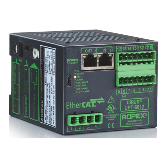
Page 19: Device Functions
EtherCAT interface is OK. UPT-6012 P ROCE S S CONTROL E QUI P M E NT 24V POWER Lit if external 24VDC power E 464680 www. ROPEX (green LED) supply is present. Made in Germany Version 2 UPT-6012 Seite 19... -
Page 20: Ethercat Communication
Device functions In addition to the functions shown above, the LEDs also indicate various controller operating states. These states are described in detail in the table below: Blinks slowly (1 Hz) Blinks fast (4 Hz) Lit continuously AUTOCAL requested but RS bit set (reset) function blocked (e.g. -
Page 21: Ethercat ® Slave Information (Esi)
The ESI file ROPEX RES-5012 UPT-6012 V1.2.xml of the UPT-6012 contains all essential controller information for the con- figuration, e.g. the I/O data description, parameter descriptions, error messages etc. The ESI file can be requested by e-mail (support@ropex.de) or downloaded from our website (https://ropex.de). -
Page 22: Input Data
Device functions Start temperature (signed) Name: Bit no.: Input data The term "input data" refers to the data that is transferred from the EtherCAT ® master to the UPT-6012. It contains the set point as well as the control functions such as START or AUTOCAL for the UPT-6012. These functions are explained in the following. - Page 23 Device functions The base resistance of the heatsealing element increases during the operation continuously (deter- mined by the design). Therfore the AUTOCAL function must be performed approximately every 100000 sealing cycles to prevent measurement errors of the ACTUAL temperature. 8.5.2 Start (ST) When the START bit is set (ST bit = 1), the controller’s internal set / actual comparison is enabled and the heating element is heated to the SET temperature.
-
Page 24: Output Data
Device functions This reference value serves to calculate the deviation from the calibration value for all subsequent calibrations (ini- tiated with the AC bit). This deviation helps you assess aging of the heating element. The deviation from the calibration value is queried by means of the object 0x4306. 8.5.6 Channel selection (CH0…CH2) The temperature controller has separate memories for up to eight calibration data records. - Page 25 Device functions 8.6.4 Warning active (WA) This bit can be set in addition to the AL bit. If the WA bit is set, a warning is output to indicate the current fault. In this case, the alarm relay is not active. 8.6.5 Temperature achieved (TE) The TE bit is set if the actual temperature exceeds 95% of the set temperature.
- Page 26 Device functions a.) Temperature not ok b.) Temperature ok Actual value Actual value Set+ Δϑ Set+ Δϑ high high Setpoint Setpoint Set+ Δϑ Set+ Δϑ Time Time ST bit ST bit Time Time TO bit TO bit Time Time ± The limits of the tolerance band are adjustable up to a maximum of 99 K.
- Page 27 Device functions 8.6.13 Error codes If a fault is signalled (AL bit = 1), you can determine the exact cause with the help of the error code. The error code is contained in the third word at bit positions 0…9 ( section 8.19 "Error messages" on page 47). Version 2 UPT-6012 Seite 27...
-
Page 28: Object Dictionary
Device functions Object dictionary Index: Acces Data Name Range Default value type index 1000 Device Type UINT32 1001 Error Register 0…255 UINT8 1008 Manufacturer Device Name UPT-6012 STRING UINT8 100A Manufacturer Software Version UINT32 1018:00 Identity Object UINT8 1018:01 Vendor ID 0x00000576 UINT32 1018:02... - Page 29 Device functions Index: Acces Data Name Range Default value type index 1A00:05 SubIndex 005 0x30000501 UINT32 1A00:06 SubIndex 006 0x30000601 UINT32 1A00:07 SubIndex 007 0x30000701 UINT32 1A00:08 SubIndex 008 0x30000801 UINT32 1A00:09 SubIndex 009 0x30000901 UINT32 1A00:0A SubIndex 010 0x30000A01 UINT32 1A00:0B SubIndex 011...
- Page 30 Device functions Index: Acces Data Name Range Default value type index 2000:09 Reserved_2 BIT5 3000:00 Inputs UINT8 3000:01 Actual temperature -99…999 INT16 3000:02 0 (off), 1 (on) BOOL 3000:03 0 (off), 1 (on) BOOL 3000:04 0 (off), 1 (on) BOOL 3000:05 0 (off), 1 (on) BOOL...
- Page 31 Device functions Index: Acces Data Name Range Default value type index 4005 Diagnosis off (0), on (1) UINT8 4006 Measurement impulse duration 17…30 UINT8 (0.1 ms units) (1.7…3.0 ms) 4007 Data format Little Endian Little Endian (Intel) UINT8 (Intel) (0), Big Endian (Moto- rola) (1) 4008:00...
- Page 32 Device functions Index: Acces Data Name Range Default value type index 4011 Temperature-OK-bit (output 1) off (0), UINT8 active, if active, if ACT=SET ACT=SET active, if ACT=SET with latch (2) 4012 Hold mode off (0), on (1), UINT8 2 seconds (2) 4300 System date UINT32...
- Page 33 Device functions Index: Acces Data Name Range Default value type index 4306:08 SubIndex 008 -10000…10000 INT16 (-100.00…100.00%) 4307 Passes through current transformer 1…9 UINT8 4308:00 Calibration resistance UINT8 4308:01 SubIndex 001 0…65535 UINT16 (0…6553.5mΩ) 4308:02 SubIndex 002 0…65535 UINT16 (0…6553.5mΩ) 4308:03 SubIndex 003 0…65535...
- Page 34 Device functions 8.7.1 Temperature range and alloy This parameter determines both the temperature range and the heating element alloy. You can overwrite the set- ting of the rotary coding switch ( section 7.2.2 "Configuration of the rotary coding switch for the temperature range and alloy"...
- Page 35 Slowly increase the correction factor, starting either with the lowest value (50%) or with the value recommended in the ROPEX Application Report minus 25%, until the actual temperature at the end of the heating impulse cor- responds to the set temperature.
- Page 36 Device functions Start temperature if cooling Temperature system faulty Set start temperature Time Start temperature if cooling system OK If the cooling system is intact, curve 1) applies. If the cooling system is faulty, curve 2) applies instead because the water is no longer cooled. The temperature never falls below the value set with this menu step. In this case, the controller ignores the next heatup command.
- Page 37 The high and low tolerance limits cannot be set in the ROPEX visualization software. The same limits apply as with the TO bit. They can only be set in the parameter data ( section 8.7 "Object dictionary" on page 28).
-
Page 38: Integrated Web Server
You can go direct to the official ROPEX website by clicking on the ROPEX logo in the top right-hand corner. The web server uses JavaScript and has been successfully tested with Internet Explorer 9, 10, and 11 as well as with Microsoft Edge. - Page 39 Device functions 8.8.1 Home page This page contains general product information under "Device Information", for instance the product name, serial number, firmware version, MAC address, and real-time Ethernet protocol. You can also download the correct ® device description file for your product here ( section 8.3 "EtherCAT Slave Information (ESI)"...
- Page 40 Device functions Under "Counters" you see a list of all cycle and operating hours counters, which are useful for statistical purposes. 8.8.4 Protocol page You can download and display the device protocol for the temperature controller on this page. You see the overall size of the protocol ("Total event entries") as well as the upload progress.
- Page 41 Device functions If any new events occur while this page is displayed, you do not see them until you refresh the list by clicking on the "Protocol" menu again. 8.8.5 Graphic page The temperature controller has an internal memory which can store temperature curves over a period of up to 5 seconds.
-
Page 42: Undervoltage Detection
Device functions These initial calibration resistances are the basis for the calculation of the calibration deviation. Each execution of the AUTOCAL function will calculate both, the absolute calibration resistance and likewise the percentual calibra- tion deviation towards the initial calibration resistance. These values are displayed on the Calibration page. -
Page 43: Temperature Meter (Actual Value Output)
Device functions 8.10 Temperature meter (actual value output) The UPT-6012 supplies an analog 0…10 VDC signal, which is proportional to the real ACTUAL temperature, at terminals 17+18. UPT-6012 Max. 5mA Actual value output 0…10 VDC 0…10 VDC Temperature meter e.g. ATR-3 Voltage values: 0 VDC 0 °C... -
Page 44: Booster Connection
An indicating instrument can be connected to this output in order to visualize the temperature of the heating ele- ment. The ROPEX ATR-x temperature meter is optimally adapted to this application in every respect (size, scale, dynamic behaviour) and can be used for this, if needed ( section 13 "How to order" on page 56). -
Page 45: Aux Interface
The number of heatsealing cycles executed since the controller was shipped is stored in the internal memory (ST bit = 1). This is a read-only counter which cannot be reset. It can be displayed in the ROPEX visualization soft- ®... -
Page 46: System Monitoring / Alarm Output
Device functions The built-in clock can be set and read out in the ROPEX visualization software ( section 8.12 "USB interface for ® visualization software ROPEXvisual " on page 44) or using the acyclic services of the EtherCAT ® interface. The date and time can be read out but not set via the integrated server. -
Page 47: Error Messages
If a ROPEX temperature meter (e.g. an ATR-x) is connected to the controller’s analog output, the temperature indication can be directly assigned to the error codes if an alarm is signalled. - Page 48 Device functions Part 1 of 3: Error messages (faults) NOTE: The error messages shown here are output as faults (constant error voltage at actual value output, alarm LED lit continuously, alarm relay energized). Act. val. Action if machine Error output Action if machine already operated, Cause...
- Page 49 Device functions Part 2 of 3: Error messages (warnings) NOTE: The specified error messages are initially output as warnings (actual value output jumps back and forth between two values, alarm LED blinks, alarm relay de-energized). When the START signal is activated, the warning changes to a fault (actual value output no longer jumps back and forth, see bold italic values, alarm LED lit continuously, alarm relay energized).
- Page 50 Device functions Part 3 of 3: Error messages (warnings) NOTE: The specified error messages are initially output as warnings (actual value output jumps back and forth between two values, alarm LED blinks, alarm relay de-energized). When the START signal is activated, the warning changes to a fault (actual value output no longer jumps back and forth, see bold italic values, alarm LED lit continuously, alarm relay energized).
-
Page 51: Fault Areas And Causes
Device functions 8.20 Fault areas and causes Temperature controller HARDWARE The table below explains the possible fault causes. Fault area Explanation Possible causes Load circuit interrupted after U - Wire break, heating element break - Contact to heating element is defective pickoff point ... -
Page 52: Factory Settings
Factory settings Fault area Explanation Possible causes - Hardware fault (replace controller) Internal device fault / no line - Jumper for alarm relay not connected or incorrectly con- voltage nected - No line voltage Factory settings ® The CIRUS UPT-6012 temperature controller is configured at the factory as follows: Rotary coding switch Heatsealing element alloy: 1700 ppm/K... -
Page 53: Technical Data
Addressing: automatic by means of topology or rotary coding switch Heating element type The temperature range and temperature coefficient settings can also be specified and temperature in the ROPEX visualization software ( section 8.12 "USB interface for visualiza- ® range tion software ROPEXvisual "... - Page 54 Technical data Analog output 0…10 VDC, I = 5 mA (actual value) Equivalent to 0…300 °C or 0…500 °C Terminals 17+18 Accuracy: ±1% plus 50 mV Alarm relay = 30 V (DC/AC), I = 0.2 A, changeover contact, potential-free Terminals 12, 13, 14 Power loss Max.
-
Page 55: Dimensions
Dimensions Dimensions 75.0 90.0 Modifications (MODs) ® Owing to its universal design, the CIRUS temperature controller UPT-6012 is suitable for a very wide range of heatsealing applications. ® One modification (MOD) is available for the CIRUS temperature controller UPT-6012 for implementing special applications. -
Page 56: How To Order
50520: Continuous curr. 50 A, 520 VAC, art. no. 885509 (with UL and CSA certification) Impulse transformer For design and order specifications, see ROPEX applica- tion report Design in accordance with EN 61558 Available with UL certifications and thermal switch, if nec- essary. - Page 57 Booster B- . . . 075415: Impulse loaded 75 A, 415 VAC, art. no. 885302 100400: Impulse loaded 100 A, 400 VAC, art. no. 885304 Lines For design and order specifications, see ROPEX applica- tion report Version 2 UPT-6012 Seite 57...
-
Page 58: Index
Index Index Numbers 24 VDC supply voltage Factory settings Fault Fault areas Fuse AA bit AC bit Actual value Actual value output Heating element AG bit Heating element type AL bit Heatup timeout Alarm output Alarm relay Alloy Impulse transformer Altitude Input data Ambient conditions... - Page 59 Index Temperature meter Temperature OK RA bit Temperature range Relative humidity Thermal impulse process Replacing the heating element Time Reset Timestamp ROPEXvisual TO bit RS bit Transformer Transportation Type of construction Set point ST bit Standby mode UL file Start USB interface Start temperature Startup...
Need help?
Do you have a question about the CIRUS UPT-6012 and is the answer not in the manual?
Questions and answers