Table of Contents
Advertisement
Quick Links
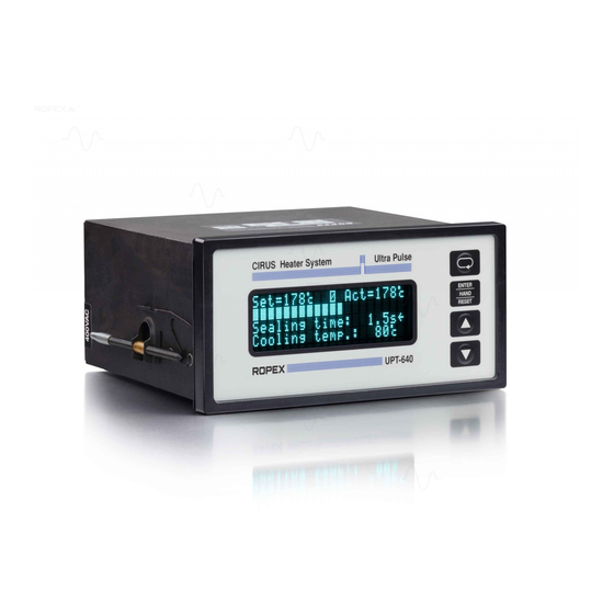
CIRUS
UPT-640
(as of SW 100)
Operating
Instructions
The UPT-640 temperature controller is a key component in an ULTRA-PULSE system, because it
is responsible for all heat management functions, i.e. controlling the temperature of the heating
element and ensuring that this highly dynamic impulse heatsealing method is accurately timed.
Important features
•
Microprocessor technology
•
LC display (green), 4 lines, 20 characters, (multilingual)
Alternatively:
VF display (blue), 4 lines, 20 characters, (multilingual)
•
Automatic zero calibration (AUTOCAL)
•
Automatic configuration of the secondary voltage and current ranges (AUTORANGE)
•
Booster connection as standard
•
Heatsealing band alloy and temperature range selectable
•
Time control, heatsealing time and cooling time settable
•
Externally or internally generated release impulse with programmable parameters
•
Configurable relay output, e.g. "end of cycle"
•
Time or temperature-controlled cooling phase
•
Signal output for "Temperature OK"
•
0...10VDC analog input for set point selection, electrically isolated
•
0...10VDC analog output for ACTUAL temperature, electrically isolated
•
24VDC control inputs for START, AUTOCAL, RELEASE and RESET, electrically isolated
•
Alarm function with fault diagnosis
•
Cooling system monitored
Industrie-Elektronik GmbH
Gansäcker 21
D-74321-Bietigheim-Bissingen (Germany)(Германия)(Alemania)
GB
TelТел: +49/(0)7142/7776-0
FaxФакс: +49/(0)7142/7776-211 InternetИнтернет:
E-MailЭл. почта:
info@ropex.de
www.ropex.de
Data subject to changeПраво на
Advertisement
Table of Contents

Related Manuals for Ropex CIRUS UPT-640


Summary of Contents for Ropex CIRUS UPT-640
- Page 1 24VDC control inputs for START, AUTOCAL, RELEASE and RESET, electrically isolated • Alarm function with fault diagnosis • Cooling system monitored Industrie-Elektronik GmbH TelТел: +49/(0)7142/7776-0 E-MailЭл. почта: info@ropex.de Gansäcker 21 FaxФакс: +49/(0)7142/7776-211 InternetИнтернет: www.ropex.de D-74321-Bietigheim-Bissingen (Germany)(Германия)(Alemania) Data subject to changeПраво на...
-
Page 2: Table Of Contents
Contents Safety and warning notes ....3 ....23 Controller functions Use . -
Page 3: Safety And Warning Notes
Line filter controller is specially adapted to CIRUS heating ele- ments. The use of an original ROPEX line filter is mandatory in order to comply with the standards and provisions The controller is not allowed to be operated mentioned in section 1.6 "Standards / CE marking" on with any other heatsealing bands because page 4. -
Page 4: Standards / Ce Marking
Warranty claims must be examined in the factory and components approved by ROPEX are used. If not, then approved by ROPEX. the equipment is operated on the user's own responsibility. -
Page 5: System Description
The trolled transformer so that set = actual. system has been evolved and optimized by ROPEX The fact that purely electrical variables are measured in GmbH in an intensive development process. Users... -
Page 6: Current Transformer Pex-W2/-W3
HS-Adapter-01” on page 8). Current transformer PEX-W2/-W3 The PEX-W2 current transformer supplied with the CIRUS UPT-640 (as of SW 100) controller is an integral part of the control system. Only this original ROPEX current transformer is allowed to be used. -
Page 7: Accessories And Modifications
Designed according to VDE 0570/EN 61558 with a one-section bobbin. Optimized for impulse operation with CIRUS temperature controllers. Specified according to the heatsealing application ( ROPEX Application Report). Communication interface CI-USB-1 Interface for connecting a RESISTRON temperature controller with diagnostic inter- face (DIAG) to the PC (USB port). -
Page 8: Modifications (Mods)
Accessories and modifications Monitoringcurrent transformer For detecting frame short-circuits on the heatsealing band. Used as an alternative to the standard PEX-W2/-W3 current transformer. Transparent front cover TFA-1 For increasing the degree of protection on the front of the controller to IP65. Also facilitates applications in the food technology sector (GMP). -
Page 9: Technical Data
Technical data Technical data Housing for front panel mounting Type of construction Dimensions (W x H): 144 x 72mm; depth: 161mm (incl. terminals) 400VAC version: 380VAC -15%…415VAC +10% (equivalent to 323…456VAC) Line voltage depending on device version ( Kap. 12 „How to order“ auf Seite 53) 47…63Hz, automatic adjustment to frequencies in this range Line frequency The temperature range and temperature coefficient can be set independently of... - Page 10 Technical data Front: IP42 (IP65 with transparent front cover, Art. No. 887000) Degree of protection Back: IP20 (+-0.2) (+-0.2) Installed in front panel cutout with (W x H) 138 x 68 Installation Fastened with clips Approx. 1.0kg (incl. connector plug-in parts) Weight Black plastic, type Noryl SE1 GFN2 Housing material...
-
Page 11: Dimensions/Front Panel Cutout
Dimensions/front panel cutout Dimensions/front panel cutout outline dimensions panel cutout front frame ±0.2 ±0.2 x 68 rubber seal mounting clamp terminal wires terminal blocks terminal blocks front panel terminal wires front frame DIP-switch to select U , I UPT-640 (as of SW 100) -
Page 12: Installation
( section 1 "Safety and warning notes" on page 3). machine. The line frequency is automatically 2. The information provided in the customized ROPEX detected by the temperature controller in the range Application Report, which is prepared by ROPEX from 47Hz to 63Hz. -
Page 13: Power Supply
Use transformers with a one section bobbin. The power, duty cycle and voltage values must be deter- SEC. mined individually according to the application ( ROPEX Application Report and "Accessories" leaflet for impulse transformers). Wiring The wire cross-sections depend on the application (... -
Page 14: Line Filter
CE mark. The wiring instructions contained in section 7.3 "Power ROPEX line filters are specially optimized for use in supply" on page 13 must be observed. RESISTRON control loops. Providing that they are Large cross-section wire to ground max. -
Page 15: Wiring Diagram (Standard)
Only principal diagram. externally to prevent Heating/sensor elements, electrostatic impulse transformer and wiring charging! must be determined individually according to the application (see ROPEX-Application Report). AUTOCAL with 24VDC signal 0V (Internal ground) RESET Terminal 2 with 24VDC signal START (HEAT) TEMP. -
Page 16: Wiring Diagram With Booster Connection
Only principal diagram. externally to prevent Heating/sensor elements, electrostatic impulse transformer and wiring charging! must be determined individually according to the application (see ROPEX-Application Report). AUTOCAL with 24VDC signal 0V (Internal ground) RESET Terminal 2 with 24VDC signal TEMP. IN... -
Page 17: Startup And Operation
Diagnostic interface (on rear of controller) Nameplate Clips Display Rear view of the controller Printed wiring diagram ROPEX E6014431 19 20 21 22 23 24 25 26 16 17 18 19 20 21 22 23 24 25 26 SEC. PRIM. -
Page 18: Controller Configuration
500°C shall be used after confirmation of The menu language can be changed on the controller ROPEX only. The lifetime of the UPT heating ele- without interrupting operation. It is set with step 201 in ments is significantly reduced when using higher the Configuration menu: sealing temperatures. - Page 19 Startup and operation Other settings are available in this menu when time 8.3.7 Relay K1 (without time control) control (timer function) is active. They are described in The function of relay K1 is specified with step 212 in the section 9.23.6 "Relay K1 (with time control)" on Configuration menu.
- Page 20 Startup and operation 3. "Active if Tact = Tset", with latch function If the temperature diagnosis is not activated by the time the "START" signal is deactivated (i.e. if the ACTUAL (factory setting) "Output 1" is conductive if the actual value is inside temperature does not exceed the upper or lower tole- specified temperature...
-
Page 21: Heating Element
Startup and operation Heating element sons who are familiar with the associated risks and warranty provisions. 8.4.1 General 8.5.1 Initial startup The heating element is a key component in the control Prerequisites: The controller must be correctly installed loop, since it is both a heating element and a sensor. and connected (... - Page 22 ( Kap. 8.3 „Controller configuration“ auf Seite 18 ment will be compensated. and ROPEX Application Report). Repeat the zero point calibration after the controller has been confi- If the heatsealing temperature is selected via gured correctly.
-
Page 23: Controller Functions
> 2 sec. Press (Hold): Return to home position ENTER HAND RESET "ENTER" key ENTER function: Save values ROPEX UPT-640 HAND function: Manual mode RESET function: Reset after alarm "UP" and "DOWN" keys for setting values Press (< 2 sec.): Slow change Hold (>... - Page 24 Controller functions a digital value and the ACTUAL temperature as a digital 9.2.2 Display in home position value and a dynamic bar. If time control (timer function) If no settings are entered on the controller and no error is active, the time control settings are also displayed. message are present, the display is in the home posi- tion, in other words it indicates the SET temperature as Specified heatsealing...
-
Page 25: Navigation In The Menus
Controller functions troller alarm is not active. In this case, the Alarm menu Navigation in the menus is opened instead. If the display is in the home position or an alarm is indi- 9.3.1 Navigation in menus without a fault cated and you press the "MENU"... - Page 26 Controller functions can then activate the "AUTOCAL" function by pressing 9.3.2 Navigation in menus with a fault the "ENTER" key ( section 9.8 "Automatic zero cali- If an alarm is signaled, the controller switches to the bration (AUTOCAL)" on page 32). Alarm menu.
-
Page 27: Menu Structure
Controller functions Menu structure Settings Configuration Power-up message Home position Language 1) Time control: ON 2) Time control: OFF Factory settings 101 Heatsealing temp. 3) TCR variable 4) TCR not variable Alloy 102 Preheating temp. 5) Cooling mode: abso- lute, relative, time 6) Cooling mode: none 204 Temp. - Page 28 Controller functions Configuration Continued from previous page Heatup timeout 220 Meas. imp. length Autocomp "Output 1" Starting temp. 225 Temperature unit Back to home position UPT-640 (as of SW 100)
-
Page 29: Two-Digit Numbering System Up To Software Revision 022
Controller functions revision 022. Three-digit numbers were introduced in Two-digit numbering system software revision 100 to improve the clarity of the menu up to software revision 022 structure. The table below compares the two numbering systems: A system of one and two-digit numbers was used for the Settings and Configuration menus up to software Numbering Numbering... -
Page 30: Temperature Setting (Set Point Selection)
Controller functions aling band will not be heated up when the "START" Temperature setting (set point signal is activated or the "HAND" key is pressed. selection) The set heatsealing temperature is displayed in the main menu once it has been entered. The heatsealing temperature can be set on the UPT-640 (as of SW 100) controller in three ways: If the heatsealing temperature is specified via... -
Page 31: Output
0…500°C. An indicating instrument can be connected to this output in order to visualize the temperature of the heat- sealing band. The characteristics of the ROPEX ATR-x temperature meter (size, scaling, dynamic response) are ideally UPT-640 (as of SW 100) -
Page 32: Automatic Zero Calibration (Autocal)
Controller functions suited to this application ( section 4 "Accessories and • By means of a 24VDC signal at terminals 20+25. modifications" on page 7). It not only facilitates SET-ACTUAL comparisons, but 24VDC UPT-640 also enables other criteria such as the heating rate, set AUTOCAL point reached within the specified time, cooling of the heatsealing band etc. -
Page 33: Start" Signal (Heat)
Controller functions the display is in the home position. You should always wait for the heatsealing band and the bar to cool down (to ambient 2. Time control on (activated): temperature) before activating the "AUTOCAL" If time control (timer function) is on, activating the function. -
Page 34: Reset" Signal
Slowly increase the correction factor – starting either with the lowest value (50%) or with the value recom- mended in the ROPEX Application Report minus 25% – to the indicated hold value = set temperature. The correction factor should be checked, and if neces- sary corrected, whenever the machine is operated or ≥... -
Page 35: Maximum Starting Temperature
Controller functions run, to enable the optimum working parameters to be 9.12 Maximum starting temperature established correctly. You can set the required maximum starting tempera- ture in step 224. This temperature is the maximum per- missible actual value at the start time. The value is 9.13 Cycle counter determined by the controller at the start of each impulse... -
Page 36: Measuring Impulse Duration
The various hold modes are shown below: step 220. It may be necessary to set a measuring impulse that is longer than the default 1.7ms for certain START applications ( ROPEX Application Report). signal 24VDC 9.16 Locking the "HAND" key The "HAND"... -
Page 37: Disabling The Configuration Menu
HAND RESET pressing the "MENU" key for 2.0seconds while the power-up message is displayed (after switching on the ROPEX controller, section 9.2.1 "Power-up message" on UPT-640 page 23). The display then shows a message confir- ming that the disable function is active for 3.0seconds before returning to the home position. -
Page 38: Diagnostic Interface/Visualization
"START" signal is deactivated before the end of the cooling phase - or if the "RESET" signal is The ROPEX visualization software is described in a activated - the timeout is interrupted. separate document. If time control is on, activating the "START" signal starts the internally parameterized timeout. - Page 39 Controller functions The active cooling phase is subsequently marked with of the internal time control cannot be started with the direction arrow at the end of the heating phase. this key. START signal 24VDC ACTUAL The direction arrow disappears again at the end of the temp.
- Page 40 Controller functions The starting delay can be set in the range from 0 to 2. "Relative" 9.99s. A delay of 0s is defined as the factory setting. In The cooling phase ends when the ACTUAL tempe- this case, the heating process begins as soon as the rature falls to a value corresponding to X% of the "START"...
- Page 41 Controller functions elapses. This time can be set between 0 and 9.99s. 9.23.5 Setting the cooling value The factory setting is 1.00s. After the cooling phase has been configured with step 210 in the Configuration menu ( section 9.23.4 9.23.6 Relay K1 (with time control) "Setting the cooling mode"...
- Page 42 Controller functions The possible settings are shown below: ance band, relay K1 is deactivated (see graph below). START signal 24VDC Actual value Set+ Δϑ upper ACTUAL Setl+ Δϑ 95% of set point lower temperature end of cooling Time NO contact of Relay K1 Closed Relay K1...
- Page 43 Controller functions If time control (timer function) is active, the switching 9.23.7 “Output 1“/ output at terminals 20+21 ("Output 1") can be parame- „Temperature OK“ signal terized in the same way as relay K1. The options for (with time control) "Output 1"...
-
Page 44: Release Impulse
Controller functions lying a short heat impulse and simultaneously tautening 9.24 Release impulse The principle is shown in the diagram below. If a film sticks to the heating element after the heatse- aling process, it can be released by subsequently app- The sealing impulse The sealing bar A release impulse is... - Page 45 Controller functions • By means of a control contact at terminals 2+19. 9.24.1 Temperature setting The temperature of the release impulse can either be max. set in step 115 or specified by applying an external UPT-640 voltage at the analog input (terminals 23+20). Release The release impulse temperature is set in the impulse...
-
Page 46: System Monitoring/Alarm Output
Error code output via the 0 to 10VDC The error codes described below can also be displayed actual value output (terminals 20+24): in the ROPEX visualization software ( section 9.21 "Diagnostic interface/visualization software"... - Page 47 Controller functions UPT-640 (as of SW 100)
- Page 48 Controller functions UPT-640 (as of SW 100)
- Page 49 Controller functions UPT-640 (as of SW 100)
-
Page 50: Fault Areas And Causes
Controller functions 9.27 Fault areas and causes Temperature controller HARDWARE The table below explains the possible fault causes. Fault area Explanation Possible causes Load circuit interrupted after U - Wire break, heatsealing band break - Contacting to heatsealing band defective pickoff point ... -
Page 51: Factory Settings
Factory settings Factory settings The CIRUS temperature controller UPT-640 (as of SW 100) is configured in the factory as follows: Values in the Settings Settings menu and Configuration No. 101 Heatsealing temperature: 0°C menus No. 102 Preheating temperature: 0°C No. 103 Starting delay: No. -
Page 52: Customer Settings
"MENU", cursor "UP" or cursor "DOWN" keys. tion menus as "customer settings". These "cus- Step 203 then appears on the display. tomer settings" are independent of the Ropex settings. Machine-specific settings can be stored in The language which is selected with step 201 the controller in this way. -
Page 53: How To Order
Line filter LF- . . 480 06: Continuous current 6A, 480VAC, Art. No. 885500 35: Continuous current 35A, 480VAC, Art. No. 885506 Impulse transformer See ROPEX Application Report for design and ordering information Communication interface CI-USB-1 Art. No. 885650 Temp. meter ATR- . -
Page 54: Index
Index Index Accessories HEAT Actual value output Heating element Adapter for top hat rail mounting Heatsealing band type Additional relay K1 Heatsealing time Alarm output Heatup timeout Alarm relay Hold mode Alloy Ambient temperature Analog temperature meter Impulse transformer Application Installation Application Report AUTOCAL... - Page 55 Index Type of construction Temperature coefficient Temperature diagnosis Undervoltage detection Temperature indication Temperature meter Temperature OK View of controller Temperature OK signal Visualization software Temperature range Temperature setting Temperature unit Wiring Time control Wiring diagram Timer function Transformer UPT-640 (as of SW 100)
Need help?
Do you have a question about the CIRUS UPT-640 and is the answer not in the manual?
Questions and answers