Table of Contents
Advertisement
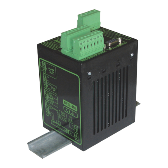
RESISTRON
RES-408
Operating
Instructions
Important features
•
Microprocessor technology
•
Separate terminal for operation and display
•
Automatic zero calibration (AUTOCAL)
•
Automatic optimization (AUTOTUNE)
•
Automatic configuration of the secondary voltage and current ranges
(AUTORANGE, as of May 2006)
•
Automatic phase angle compensation (AUTOCOMP, as of June 2006)
•
Automatic frequency adjustment
•
Wide current and voltage range
•
0...10VDC analog output for ACTUAL temperature
•
24VDC control signals for START and PREHEAT with electrical isolation
•
Alarm function with fault diagnosis
•
Heatsealing band alloy and temperature range selectable as standard (as of June 2006)
ROPEX Industrie-Elektronik GmbH
Adolf-Heim-Str. 4
74321 Bietigheim-Bissingen (Germany)
Tel.: +49 (0)7142-7776-0
Fax: +49 (0)7142-7776-211
E-Mail:
info@ropex.de
Internet:
https://ropex.de
Data subject to change
Advertisement
Table of Contents

Subscribe to Our Youtube Channel
Related Manuals for Ropex Resistron RES-408


Summary of Contents for Ropex Resistron RES-408
- Page 1 24VDC control signals for START and PREHEAT with electrical isolation • Alarm function with fault diagnosis • Heatsealing band alloy and temperature range selectable as standard (as of June 2006) ROPEX Industrie-Elektronik GmbH Tel.: +49 (0)7142-7776-0 E-Mail: info@ropex.de Adolf-Heim-Str. 4...
-
Page 2: Table Of Contents
Contents General information ....3 Controller functions ....30 Copyright . -
Page 3: General Information
The temperature coefficient must be taken from the ROPEX application report and must be set accordingly. The use of incorrect alloys with a too low temperature coefficient and incorrect coding of the ®... -
Page 4: Impulse Transformer
The use of an original ROPEX line filter is mandatory in order to comply with the directives mentioned in section "DECLARATION OF CONFORMITY" on page 6. This device must be installed and connected according to the instructions contained in section "Power supply"... -
Page 5: Disposal
General information Disposal This device is subject to Directive 2012/19/EU concerning the reduction of the increasing amount of waste electrical and electronic equipment and the disposal of such waste in an environmentally sound way. To guarantee proper disposal and / or the recover of reusable material, please take the device to a designated municipal collection point and observe local regulations. - Page 6 We also wish to point out that the transformer which is used must be designed in accordance with VDE 0551/EN 61558 or UL 5058 for safety reasons. July 12, 2020 J. Kühner (CEO) ROPEX Industrie-Elektronik GmbH Adolf-Heim-Str. 4 74321 Bietigheim-Bissingen (Germany) Page 6...
-
Page 7: Application
Application Application This RESISTRON temperature controller is an integral part of the "series 400", the outstanding feature of which is its microprocessor technology. All RESISTRON temperature controllers are used to control the temperature of heating elements (heatsealing bands, beaded bands, cutting wires, heatsealing blades, solder elements etc.), as required in a variety of heatsealing processes. -
Page 8: Description Of The Controller
Description of the controller the system components, in other words the heatsealing band, the impulse transformer, the wiring, the timing sig- nals and the controller itself, are compatible with one another. We will be pleased to contribute our many years of experience your towards optimizing heatsealing system. -
Page 9: Accessories And Modifications
Designed according to VDE 0570/EN 61558 with a one-section bobbin. Optimized for impulse operation with RESISTRON temperature controllers. Specified according to the heatsealing application ( ROPEX Application Report). CI-USB-1 communication interface Interface for connecting a RESISTRON temperature controller with a diagnostic interface (DIAG) to the PC (USB port). -
Page 10: Modifications (Mods)
Accessories and modifications Booster External switching amplifier, necessary for high primary currents (continuous current > 5A, pulsed current > 25A). Monitoringcurrent transformer For detecting frame short-circuits on the heatsealing band. Used as an alternative to the standard PEX-W2/-W3 current transformer. Modifications (MODs) Owing to its universal design, the RES-408 RESISTRON temperature controller is suitable for a very wide range of heatsealing applications. - Page 11 Accessories and modifications This modification is supplied as standard with all controllers manufactured as of June 2006 ( section 10.2.2 "Configuration of the rotary coding switch for the temperature range and alloy (as of June 2006)" on page 26). Switch Temp.
-
Page 12: Technical Data
The temperature range and temperature coefficient settings can also be specified range in the ROPEX visualization software ( section 11.19 "Diagnostic interface / vis- ualization software (as of June 2006)" on page 51) in addition to using the rotary coding switch (see below): Temperature range: 200°C, 300°C, 400°C or 500°C... -
Page 13: Controller/Terminal Compatibility
Controller/terminal compatibility Alarm relay = 30V (DC/AC), I = 0.2A, changeover contact, potential-free Terminals 12, 13, 14 Can be inverted by means of a plug-in jumper Maximum load = 5A (duty cycle = 100%) (primary current of = 25A (duty cycle = 20%) impulse transformer) Power loss max. - Page 14 Controller/terminal compatibility Please pay attention to the controller and terminal versions when ordering spare parts. The controller may have to be exchanged together with the terminal. Refer to the compatibility table below: Page 14 RES-408 Version 1...
-
Page 15: Dimensions
Dimensions New version (as of June 2006): Controller type Art. No. Compatible with RES-408/115VAC 740841 Terminal T-408-1 RES-408/230VAC 740842 Art. No. 885441 RES-408/400VAC 740843 Old version (up to May 2006): Controller type Art. No. Compatible with RES-408-0-3/115VAC 740801 or 740831 RES-408-0-3/230VAC 740802 or 740832 Terminal T-400... -
Page 16: Installation
( section 7 "Controller/terminal compatibility" on page 13). 6. Wire the system in accordance with the instructions in section 9.3 "Power supply" on page 19 and the ROPEX Application Report. The information provided in section 9.2 "Installation steps" on page 18 must be heeded additionally. - Page 17 Installation Check the tightness of all system connections, including the terminals for the impulse transformer winding wires. 7. Make sure that the wiring conforms to the relevant national and international installation regulations. Version 1 RES-408 Page 17...
-
Page 18: Installation Steps
Installation Installation steps Use heatseal bands with suitable temperature coefficient Heatseal element push-on with coppered ends connectors Heatsealing band R= f (T) No additional Connect U measuring resistance wires directly to in secondary Note heatsealing band ends circuit number Sufficient wire of turns Twisted cross-section... -
Page 19: Power Supply
Connect core to ground. Use transformers with a one section bobbin. The power, duty cycle and voltage values must be deter- mined individually according to the application ( ROPEX SEC. Application Report and "Accessories" leaflet for impulse transformers). -
Page 20: Line Filter
ROPEX line filters are specially optimized for use in RESISTRON control loops. Providing that they are installed and wired correctly, they guarantee compliance with the EMC limit values. You can find the exact specification of the line filter in the ROPEX Application Report calculated for your particular heatsealing application. - Page 21 Installation 9.5.1 PEX-W4 terminal wires terminal block Snap-on for DIN-rail 35 x 7.5 mm or 35 x 15 mm (DIN EN 50022) 9.5.2 PEX-W5 Mounting on DIN-rail 35 x 7.5 mm or 35 x 15 mm (DIN EN 50022). Version 1 RES-408 Page 21...
-
Page 22: Wiring Diagram (Standard)
Current transformer May 2006 (Internal ground) No external °C grounding allowed! ANALOG OUTPUT +0...10VDC ROPEX T-408 SEALHE AT PREHEAT HOLD ENTER HAND RESET Display- and operation panel Up to production date March 2003 the standard output power circuit (terminals 3+4) has NO function when the booster-connection (MOD 26) is installed. -
Page 23: Wiring Diagram With Booster Connection (Mod 26)
Current transformer May 2006 (Internal ground) °C No external grounding allowed! ANALOG OUTPUT +0...10VDC ROPEX T-408 SEALHE AT PREHEAT HOLD ENTER HAND RESET Display- and operation panel Up to production date March 2003 the standard output power circuit (terminals 3+4) has NO function when the booster-connection (MOD 26) is installed. -
Page 24: Startup And Operation
Startup and operation Startup and operation 10.1 View of the controller RES-408 controller LEDs Terminals Connection for terminal Wiring diagram Nameplate Coding switches and plug-in jumpers T-400 or T-408-1 terminal Nameplate Cable connection Display Fixing clips (4x) Operator keys Page 24 RES-408 Version 1... -
Page 25: Controller Configuration
Set the DIP switches for matching the secondary voltage U and the secondary current I to the correct position for your application. You can find the exact configuration of the DIP switches in the ROPEX Application Report calculated for your particular application. Factory settings DIP switch DIP switch 1...10V... - Page 26 2006)" on page 10). If the switch is set to "9" (as of June 2006), other temperature ranges and alloys can be selected in the ROPEX visualization software ( see section 11.19 "Diagnostic interface / visualization software (as of June 2006)" on page 51).
-
Page 27: Heatsealing Band
Startup and operation 10.3 Heatsealing band 10.3.1 General The heatsealing band is a key component in the control loop, since it is both a heating element and a sensor. The geometry of the heatsealing band is too complex to be discussed at length here. We shall therefore only refer to a few of the most important physical and electrical properties. - Page 28 3. In the case of controllers manufactured up to May 2006, the DIP switches on the controller must be set according to the ROPEX Application Report and depend on the heatsealing band that is used (section 10.2 "Controller configuration" on page 25).
- Page 29 "ALARM" LED blinks slowly (1Hz) on all controllers manufactured as of June 2006. In this case the controller configuration is incorrect ( section 10.2 "Controller configuration" on page 25 and ROPEX Applica- tion Report). Repeat the calibration after the controller has been configured correctly.
-
Page 30: Controller Functions
AUTOCAL process. RESISTRON RES- 408 Temperature controller ROPEX Tel:+49(0)7142-7776-0 Made in Germany In addition to the functions shown in the diagram above, various operating states are indicated by the controller LEDs. These states are described in detail in the table below:... - Page 31 Controller functions T-408-1 terminal LED display, 5 characters ROPEX T-408 SEALHEAT PREHEAT 1 Yellow LED: Heatung up/temp. control to set temperature active HOLD 2 Yellow LED: PREHEAT active ENTER 3 Green LED: Hold mode active HAND RESET “UP” and “DOWN” keys for setting values Press (<...
- Page 32 Green LED, indicates pulses in measure- POWER ON ment mode. In control mode, luminous OUTPUT intensity is proportional to heating current. RESISTRON μP-Controller ROPEX INDUSTRIE - ELEKTRONIK T-400 terminal LED display, 5 characters ROPEX SEALHEAT PREHEAT 1 Red/Green LED: Red, during heating up Green, set temp.
-
Page 33: Display
A power-up message appears on the display for approximately 3 seconds when the controller is switched on. On controllers manufactured as of June 2006, this message shows the SW revision of the terminal for the first 1.5s (e.g.: 00.105) and the SW revision of the controller for the next 1.5s (e.g.: 00.105). ROPEX T-408 SEALHEAT... -
Page 34: Navigation In The Menus
Controller functions 11.3 Navigation in the menus 11.3.1 Navigation in menus without an alarm A "MENU" key is provided for navigating through the various menu steps. By pressing this key briefly (<2s) at any time, you can jump to the next menu step. By pressing the key for longer (>2s), you can return to the home position from anywhere in the menu structure, providing a controller alarm is not active. -
Page 35: Menu Structure
Controller functions 11.4 Menu structure 1) AUTOCOMP: OFF Power-up message 2) AUTOCOMP: ON °C Home position SH Heatsealing temp. Preheat temp. Autocal? Autocal Autocomp? Autocomp Fault Alarm Autocal? Autocal Version 1 RES-408 Page 35... -
Page 36: Menu Steps
Controller functions 11.5 Menu steps Name Description Setting range °C Home position The current actual value appears on the terminal display. The heatsealing band can be heated man- ually (to the specified heatsealing or preheat tem- perature) by pressing the "HAND" key. [HAnd] The heatsealing band can be heated manually (to Hand menu... - Page 37 Controller functions Name Description Setting range [AutoCal] The AUTOCAL function matches the controller to Controllers manufactured Automatic calibra- the current and voltage signals that are present in up to May 2006: tion AUTOCAL the system. Setting not possible The required calibration temperature can be set with the "UP"...
-
Page 38: Temperature Setting (Set Point Selection)
"START" signal is activated or the "HAND" key is pressed. The 1…39°C setting range is not available on controllers manufactured as of June 2006. 11.7 Temperature indication / actual value output If the display is in the home position ("°C"), the ACTUAL temperature is indicated. ROPEX T-408 SEALHEAT PREHEAT HOLD... -
Page 39: Output
Controller functions In addition, the RES-408 controller outputs an analog 0…10VDC signal, which is proportional to the real ACTUAL temperature, at terminals 17+18. RES-408 Actual value max. 5mA R=33ohm output 0…10VDC 0…10VDC Temperature meter e.g. ATR-3 Voltage values: 0VDC 0°C 10VDC ... -
Page 40: Automatic Zero Calibration (Autocal)
An indicating instrument can be connected to this output in order to visualize the temperature of the heatsealing band. The characteristics of the ROPEX ATR-x temperature meter (size, scaling, dynamic response) are optimized for this application ( section 5 "Accessories and modifications" on page 9). -
Page 41: Heating To The Heatsealing Temperature
Controller functions You should always wait for the heatsealing band and the bar to cool down (to ambient temperature) before activating the "AUTOCAL" function. Reasons for locked AUTOCAL function: 1. The "AUTOCAL" function cannot be activated if the heatsealing band cools down at a rate of more than 0.1K/ s. - Page 42 Controller functions If a "PREHEAT" signal is used, it must be deactivated during the heating and control process. If not, the heatsealing band is heated to the set preheat temperature instead of the heatsealing tempera- ture ( section 11.10 ""PREHEAT" signal" on page 43). Page 42 RES-408 Version 1...
-
Page 43: Preheat" Signal
Controller functions 11.10 "PREHEAT" signal The heatsealing band can be heated to a specified preheat temperature with the "PREHEAT" function, in order to shorten the heating time to the selected SET temperature in time-critical applications. The preheat temperature is set with the "PH" [PreHeat] step in the Settings menu. The value selected for the pre- heat temperature must be greater than 40°C. -
Page 44: Hold Mode
Controller functions trollers manufactured up to December 2000, the same effect can be achieved by pressing the "HAND" key in the "HA" [HAnd] step. 11.11 Hold mode The behavior of the ACTUAL temperature display in the home position can be changed with the "HO" [HOld] step. The following settings are possible: 1. -
Page 45: Temperature Unit Celsius / Fahrenheit (As Of Controller Sw Revision 106 And Terminal Sw Revision 103)
Controller functions The various hold modes are shown below: START signal 24VDC ACTUAL temperature ACTUAL indication Hold OFF Hold On Hold Hold Hold On2 Hold Hold End of Heatsealing phase The "HOLD" LED on the terminal lights up if a temperature value is indicated in hold mode. 11.12 Temperature unit Celsius / Fahrenheit (as of controller SW revision 106 and ter- minal SW revision 103) - Page 46 Controller functions the „UP“ and „DOWN“ keys simultaneously when the home position is displayed. The keys must be pressed together for 2seconds minimum. ROPEX T-408 SEALHEAT PREHEAT HOLD ENTER HAND RESET The following settings are possible: 1. „Celsius“ (Factory setting) Temperature indication and value selection in Celsius (°C).
-
Page 47: Measuring Impulse Duration
The length of the measuring impulses generated by the controller can be set with this parameter. It may be nec- essary to set a measuring impulse that is longer than the default 1.7ms for certain applications ( ROPEX Appli- cation Report). -
Page 48: Temperature Diagnosis
11.15 Temperature diagnosis (as of June 2006) An additional temperature diagnosis can be activated in the ROPEX visualization software ( section 11.19 "Diagnostic interface / visualization software (as of June 2006)" on page 51). The RES-408 checks whether the ACTUAL temperature is within a settable tolerance band ("OK" window) on either side of the SET temperature. -
Page 49: Heatup Timeout (As Of June 2006)
An additional delay time (0..9.9s) can be set in the ROPEX visualization software. The first time the lower tolerance band limit is exceeded, the temperature diagnosis is not activated until the parameterized delay time has elapsed. -
Page 50: Communication Error Between The Controller And The Terminal (As Of June 2006)
Communication error between the controller and the terminal (as of June 2006) If a data communication error occurs between the T-408 terminal and the RES-408 controller or if communication is interrupted, the display on the terminal changes to indicate this (rotating segments). ROPEX T-408 SEALHEAT... -
Page 51: Diagnostic Interface / Visualization Software (As Of June 2006)
Diagnostic interface / visualization software (as of June 2006) An interface with a 6-pole Western socket is provided for system diagnostics and process visualization. This inter- face allows a data connection to be set up to the ROPEX visualization software using the ROPEX CI-USB-1 com- munication interface. -
Page 52: Error Messages
An alarm can only be reset by pressing the "RESET" key or by switching the controller off and then on again. The alarm is not reset until the key is released. ROPEX T-408 SEALHEAT... - Page 53 June 2006. The error messages are differentiated even more finely in the controller. The error codes described below can be displayed in the ROPEX visualization software ( section 11.19 "Diagnostic interface / visualization software (as of June 2006)" on page 51) to facilitate troubleshooting.
- Page 54 Controller functions Page 54 RES-408 Version 1...
- Page 55 Controller functions Version 1 RES-408 Page 55...
- Page 56 Controller functions Page 56 RES-408 Version 1...
- Page 57 Controller functions Version 1 RES-408 Page 57...
-
Page 58: Fault Areas And Causes
Controller functions 11.22 Fault areas and causes Temperaturregler HARDWARE The table below explains the possible fault causes. Fault area Explanation Possible causes Load circuit interrupted after U - Wire break, heatsealing band break - Contacting to heatsealing band defective pickoff point ... -
Page 59: Factory Settings
Factory settings Fault area Explanation Possible causes - Up to May 2006: DIP switches 4 + 5 configured incorrectly range) signal incorrect - As of June 2006: I outside permissible range from 30…500A Turns through PEX-W2/-W3 cur- - Check number of turns (two or more turns required for rent transformer incorrect currents <... -
Page 60: Maintenance
Heatup timeout: OFF timeout [X] As of June 2006: Only in ROPEX visualization software Maintenance The controller requires no special maintenance. Regular inspection and/or tightening of the terminals – including the terminals for the winding connections on the impulse transformer – is recommended. Dust deposits on the con- troller can be removed with dry compressed air. -
Page 61: How To Order
Line filter LF- . . 480 06: Continuous current 6A, 480VAC, Art. No. 885500 35: Continuous current 35A, 480VAC, Art. No. 885506 Impulse transformer See ROPEX Application Report for design and ordering information Communication interface CI-USB-1 Art. No. 885650 Version 1... - Page 62 How to order Temperature meter ATR- . 3: 300°C range, Art. No. 882130 5: 500°C range, Art. No. 882150 Booster B- . . . 400 075: Max. pulse load 75A, 400VAC, Art. No. 885301 100: Max. pulse load 100A, 400VAC, Art. No. 885304 For more accessories: "Accessories"...
-
Page 63: Index
Index Index Accessories HEAT Actual value output Heatsealing band type Alarm output Heatsealing temperature Alarm relay Heatup timeout Alloy How to order Ambient temperature Analog input Analog output Impulse heatsealing method Analog temperature meter Impulse transformer Application Installation Application Report Installation procedure AUTOCAL Installation regulations... - Page 64 Index System monitoring Transportation Type of construction Technical data Undervoltage detection Temperature coefficient Temperature control Temperature diagnosis View of the controller Temperature indication Visualization software Temperature meter Temperature range Temperature setting Wiring Temperature unit Wiring diagram Transformer Page 64 RES-408 Version 1...
Need help?
Do you have a question about the Resistron RES-408 and is the answer not in the manual?
Questions and answers