Table of Contents
Advertisement
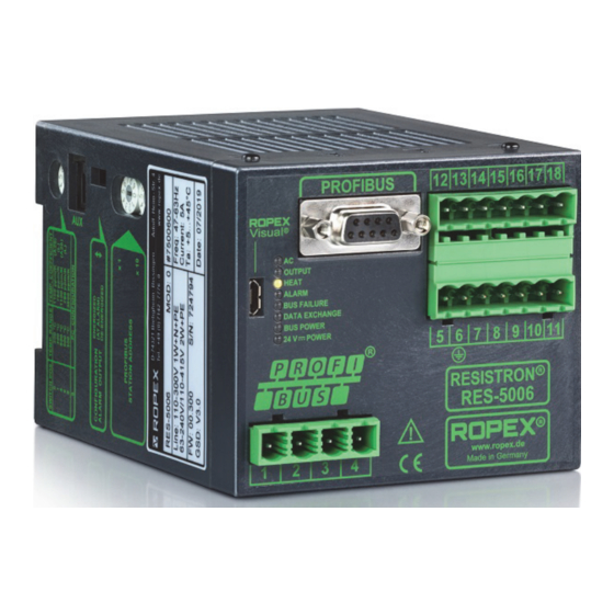
RESISTRON
RES-5006
User Guide
Important features
•
PROFIBUS DP interface for complete control
•
Automatic zeroing (AUTOCAL)
•
Automatic optimisation (AUTOTUNE)
•
Automatic configuration of the secondary voltage and current range (AUTORANGE)
•
Automatic phase correction (AUTOCOMP)
•
Automatic frequency adaptation
•
Booster output standard
•
Analogue output 0...10 VDC for ACTUAL temperature
•
Alarm function with error diagnosis
•
Heating element alloy and temperature range can be selected
•
Wide voltage range for the use of 110...415 V
•
Eight channels for administration of various calibration values
•
Micro-USB interface for ROPEXvisual
ROPEX Industrie-Elektronik GmbH
Adolf-Heim-Str. 4
74321 Bietigheim-Bissingen (Germany)
®
Tel.: +49 (0)7142-7776-0
Fax: +49 (0)7142-7776-211
E-Mail:
info@ropex.de
Internet:
https://ropex.de
Data subject to change
Advertisement
Table of Contents

Subscribe to Our Youtube Channel
Related Manuals for Ropex RESISTRON RES-5006


Summary of Contents for Ropex RESISTRON RES-5006
- Page 1 • Wide voltage range for the use of 110…415 V • Eight channels for administration of various calibration values ® • Micro-USB interface for ROPEXvisual ROPEX Industrie-Elektronik GmbH Tel.: +49 (0)7142-7776-0 E-Mail: info@ropex.de Adolf-Heim-Str. 4 Fax: +49 (0)7142-7776-211 Internet: https://ropex.de...
-
Page 2: Table Of Contents
Contents Revision list ......3 Device functions ....20 Display and operating elements . -
Page 3: Revision List
Revision list Revision list Version Change • Creation of documentation General information ® This RESISTRON temperature controller is manufactured according to EN 61010-1. In the course of its manu- facture it passed through quality assurance, whereby it was subjected to extensive inspections and tests. As a result of this, the product left our factory in perfect condition. -
Page 4: Impulse Transformer
The use of an original ROPEX line filter is mandatory in order to comply with the standards and provisions mentioned in section 2.7 "Standards / CE marking" on page 4. This device must be installed and connected according to the instructions contained in section "Power supply"... -
Page 5: Maintenance
Compliance with these standards and provisions is only guaranteed if original accessories and / or peripheral components approved by ROPEX are used. If not, then the equipment is operated on the user's own responsibility. The CE marking on the controller confirms that the device itself complies with the above-mentioned standards. -
Page 6: Use
Careless, uncontrolled disposal can cause damage to the environment and human health. By ensuring that your product is disposed of or recycled in a responsible way, you can help protect the environment and human health. This device must not be disposed of as residual waste! ®... -
Page 7: Device Features
Device features Device features ® The RESISTRON temperature controller RES-5006 is equipped with a PROFIBUS-DP interface. Through this interface, all functions and parameters can be parameterised by means of the higher level machine controller. In addition, important controller information is queried and can be processed accordingly. The ACTUAL temperature of the heating element is output through the PROFIBUS interface and through an ana- logue output 0…10 VDC. - Page 8 If this overcurrent protective device is not sufficient for the sealing application, two separate overcurrent pro- tective devices must be provided for the controller and the sealing application ( ROPEX application report). The overcurrent protective device must be located in the immediate vicinity of the device.
-
Page 9: Installation Notes
Mounting and installation Installation notes Sample depiction Use heatseal bands with suitable temperature coefficient Heatseal element push-on with coppered ends connectors Heatsealing band R= f (T) No additional Connect U measuring resistance wires directly to in secondary heatsealing band ends Note circuit number... -
Page 10: Power Supply
Connect core to ground. Use transformers with a one section bobbin. The power, duty cycle and voltage values must be deter- mined individually according to the application ( ROPEX SEC. Application Report and "Accessories" leaflet for impulse transformers). -
Page 11: Line Filter
ROPEX line filters are specially optimized for use in RESISTRON control loops. Providing that they are installed and wired correctly, they guarantee compliance with the EMC limit values. You can find the exact specification of the line filter in the ROPEX Application Report calculated for your particular heatsealing application. - Page 12 Mounting and installation 6.5.1 PEX-W4 terminal wires terminal block Snap-on for DIN-rail 35 x 7.5 mm or 35 x 15 mm (DIN EN 50022) 6.5.2 PEX-W5 Mounting on DIN-rail 35 x 7.5 mm or 35 x 15 mm (DIN EN 50022). Page 12 RES-5006 Version 1...
-
Page 13: Connection Diagram (Standard)
Mounting and installation Connection diagram (standard) PROFIBUS-PLUG Line filter SUB-D / 9-POLE RES-5006 LINE (GND pwr. supply) M24 PROFIBUS DGND controller electrically (+5 V) VP isolated (+24 V pwr. supply) P24 prim. Impulse transformer +24 VDC sec. POWER SUPPLY Heat- sealing Ground band... -
Page 14: Connection Diagram With Booster Connection
Mounting and installation Connection diagram with booster connection PROFIBUS-PLUG Line filter SUB-D / 9-POLE RES-5006 LINE Booster (GND pwr. supply) M24 PROFIBUS twisted DGND controller Max. length 1 m electrically (+5 V) VP isolated (+24 V pwr. supply) P24 prim. Impulse transformer +24 VDC... -
Page 15: Commissioning And Operation
( see section 8.19 "Error messages" on page 50). For secondary currents I less than 30 A, the secondary high-current line must be guided 2 times (or several times) through the transformer PEX-W4 or PEX-W5 ( ROPEX application report). Version 1 RES-5006... - Page 16 The setting of the rotary coding switch for temperature range and alloy can be overwritten by the parameter data ( section 8.7 "Parameter data" on page 32). When the switch position “9” is selected, additional temperature ranges and alloys can be set through the ROPEX ®...
-
Page 17: Replace And Burn In Heating Element
(factory setting) When the “Alarm relay contact opens with Alarm/PC CONFIGURATION” is selected, additional configurations for the behaviour of the alarm output can be set through the ROPEX visualisation software ( section 8.12 "USB ® interface for visualisation software ROPEXvisual "... -
Page 18: Commissioning Rules
Commissioning and operation 7.3.2 Changing the heating element ® To change the heating element, the supply voltage must be disconnected from the RESISTRON temperature controller on all pins. The heating element must be changed in accordance with the manufacturer’s instructions. After every heating element change, zeroing must be performed with the AUTOCAL function and with a cold heating element (and cold surroundings: i.e. - Page 19 (1 Hz). Then the configuration of the controller is not correct ( section 7.2 "Device configuration" on page 15, ROPEX application report). After the device configuration is correct, perform zeroing again. 10.After successful zeroing, specify a defined temperature over the PROFIBUS protocol (setpoint) and set the ST bit.
-
Page 20: Device Functions
24 V POWER LED) BUS POWER Lit if internal power supply for (green PROFINET interface is OK. RES-5006 24 V POWER Lit if external 24 VDC power www. ROPEX (green supply is present. Made in Germany Page 20 RES-5006 Version 1... -
Page 21: Profibus Communication
The GSD files in German (.GSG) and English (.GSD or .GSE) as well as the related image files .DIB for status visualisation can be requested by e-mail (support@ropex.de) or downloaded from our homepage (https:// ropex.de). -
Page 22: Profibus Protocol
Device functions After the desired GSD file has been integrated into the design tool, one of the three communication modules (“compact”, “expanded” or “complete”) must be selected. This determines the protocol over which the RES-5006 communicates with the PROFIBUS master. To take advantage of the controller’s complete range of functions, the right GSD version must be used. - Page 23 Device functions The 16 bit output data from the RES-5006 to the PROFIBUS master contain the actual value or error number and status information and have the following structure: Error no., with AL = 1 Status information Actual value (compact), with AL = 0 Name: Bit no.: 8.4.2...
- Page 24 Device functions The 2x16 bit output data contain the setpoint value in the word and the error number and status information in the word : Actual value (with prefix) Name: Bit no.: Reserve Error no. Reserve Status information Name: Bit no.: 8.4.4...
- Page 25 Device functions 8.4.5 Protocol “complete” with 4-bit error number The 2x16 bit input data contain the setpoint value in the word and the control functions in the word : Reserve Setpoint value / AC temperature Name: Bit no.: ...
-
Page 26: Input Data
Device functions Reserve Channel Reserve Control function Name: Bit no.: The 4x16 bit output data contain the actual value in the word , the status information in the word , the error number in the word , and the start temperature in the word : ... - Page 27 Device functions must be entered in the input data “Setpoint/AC temperature” during activation of the AUTOCAL function (AC- Bit = 1). This specified value must remain entered until the end of the AUTOCAL function. If too high of a temperature (greater than 40 °C) or a fluctuating specification value is specified, a corresponding error message is output (error no.115 and 116;...
- Page 28 Device functions The reset request is not processed until the RS bit is processed. The PROFIBUS communication is not interrupted by resetting of the controller. During activation of the RS bit, the actual value output goes to 0…3 °C (i.e. about 0 VDC) and the SA bit is active. This can be evaluated as feedback by the higher-level controller (e.g.
-
Page 29: Output Data
Device functions 8.5.8 Setpoint Depending on the selected temperature range ( section 8.7.1 "Temperature range and alloy" on page 33), the setpoint can be specified up to 300°C or up to 500°C. With larger setpoints, there is an internal limitation to 300°C or 500°C. - Page 30 Time The TO bit can only be set over the parameter data in the PROFIBUS master (also over DPV1). Setting over the ROPEX visualisation software is not possible. The tolerance limits can be set up to max. ±99 K. 8.6.7 Regulation active (RA) The RES-5006 has successfully accepted the START request and is in the control mode when RA bit = 1.
- Page 31 Device functions 8.6.9 Information active (IA) This bit is intended for later use and is currently not supported (always 0). 8.6.10 Standby active (SA) This bit is active when the RS bit is set. With it, the controller can detect when the controller has accepted the RS bit or the MP bit and the RS bit or MP bit will then be deleted again (“handshake”...
-
Page 32: Parameter Data
Device functions Parameter data The parameter data contain values for selection of the heating element alloy, the temperature range, the lower and upper tolerance band limit for temperature monitoring, the calibration temperature, the measurement impulse duration (only for special applications), as well as the optional heating time limit. They are transmitted at every system start from the PROFIBUS master to the RES-5006. - Page 33 Device functions Function Possible values Standard value Hold mode Off, 2 sec. Calibration temperature, channel 1 20 °C -1, 0…40 °C 26/27 Temperature coefficient, channel 1 1100 ppm/K 400…4000 ppm/K Calibration temperature, channel 2 20 °C -1, 0…40 °C 29/30 Temperature coefficient, channel 2 1100 ppm/K 400…4000 ppm/K...
- Page 34 Device functions After a change of this parameter, the AUTOCAL function must be performed. 8.7.2 Lower threshold for temperature OK Lower threshold value for the “good window”. See section 8.6.6 "Temperature OK (TO)" on page 29 and section 8.7.11 "Temperature diagnosis" on page 37. 8.7.3 Upper threshold for temperature OK Upper threshold value for the “good window”.
- Page 35 In special sealing applications, it may be necessary to compensate the phase displacement between the U measurement signals ( ROPEX application report). Use of the AUTOCOMP function can be necessary here. The AUTOCOMP function must be released for use in the parameter data ( section 8.7 "Parameter data" on page 32) or through the DPV1 protocol expansion (...
- Page 36 Device functions AC bit <2.0 s Function AUTOCOMP AUTOCAL „AUTOCAL“ „OUTPUT“ During execution of the AUTOCOMP function, the “OUTPUT” LED flashes several times and the actual value output (terminal 17+18) goes to 0…3 °C (i.e. approx. 0 VDC). 3. “AUTO” With this setting, the AUTOCOMP function is automatically started after a successful execution of the AUTOCAL function.
- Page 37 The lower and upper tolerance band limits cannot be set through the ROPEX visualisation software. These are the same limits as with the TO bit. These can only be set through the parameter data ( section 8.7 "Parameter data"...
- Page 38 The Hold mode only affects output of the ACTUAL temperature over the PROFIBUS protocol and the numeric tem- perature display in the ROPEX visualisation software. Output of the ACTUAL temperature over the analogue output of the controller or the graphic drawing in the ROPEX visualisation software is not changed by this. Page 38...
- Page 39 Device functions The different Hold modes are depicted in the following image: ST bit ACTUAL temperature ACTUAL indication Hold off Hold on Hold Hold Hold 2 s Hold Hold End of heatsealing phase The settings for the Hold mode must be made in the parameter data ( section 8.7 "Parameter data" on page 32) or through the DPV1 protocol expansion (...
-
Page 40: Dpv1 Protocol Expansions
Device functions DPV1 protocol expansions 8.8.1 Identification and maintenance (I&M functions) The I&M functions (identification & maintenance) are helpful for identification and cataloguing of PROFIBUS devices. The RES-5006 supports the I&M functions 0, 1, 2, 3 and 4. Access to the I&M functions is through slot 0 and is specified in IEC 61158-6-3. - Page 41 Device functions With the DPV1 protocol expansion, there is the possibility to change these settings and functions during operation of the controller. As a result, the temperature coefficient for the heating band can be adjusted through the PLC controller during the validation process, for example. The parameters of the controller can be both read and written over this acyclical service.
- Page 42 Device functions Slot Index Parameter Range of values 16/17 Maximum temperature [°C] 200…500 (300) Temperature diagnosis 0: Deactivated 1: Activated Diagnosis delay [0.1 s] 0…99 (0) 20/21 Heating time monitoring [0.1 s] 0…999 (0) AUTOCOMP 0: off 1: on 2: AUTO Output 1 (temp-OK bit) 0: off 1: Active when Actual=Setpoint...
- Page 43 Device functions range”. To avoid inconsistencies, individual values for the date or time should be changed together with write access, that is, index 100…103 or 104…106. Slot Index Parameter Range of values 100/101 Time: Milliseconds (only whole sec- 0…59000 onds) Time: Minutes 0…59 Time: Hours...
- Page 44 Device functions Slot Index Parameter Range of values 202/203 Calibration data deviation [0.01%], channel 1 -10000…10000 (0) (-100.00…100.00%) 204/205 Calibration data deviation [0.01%], channel 2 -10000…10000 (0) (-100.00…100.00%) 206/207 Calibration data deviation [0.01%], channel 3 -10000…10000 (0) (-100.00…100.00%) 208/209 Calibration data deviation [0.01%], channel 4 -10000…10000 (0) (-100.00…100.00%) 210/211...
-
Page 45: Undervoltage Detection
Device functions Slot Index Parameter Range of values 241/242 Initial calibration resistance [0.1 mΩ], channel 0…65535 (0) (0…6553.5 mΩ) 243/244 Initial calibration resistance [0.1 mΩ], channel 0…65535 (0) (0…6553.5 mΩ) 245/246 Initial calibration resistance [0.1 mΩ], channel 0…65535 (0) (0…6553.5 mΩ) 247/248 Initial calibration resistance [0.1 mΩ], channel 0…65535 (0) -
Page 46: Temperature Display
Device functions 8.10 Temperature display (actual value output) The RES-5006 sends to the terminals 17+18 an analogue signal 0…10 VDC, which is proportional to the real ACTUAL temperature. RES-5006 max. 5 mA Actual value output 0…10 VDC 0…10 VDC Temperature meter e.g. -
Page 47: Booster Connection
PROCESS CONTROL EQUIPMENT E464680 www. ROPEX Made in Germany There is a separate documentation available for the ROPEX visualisation software. The software and the docu- mentation are available in the download area (search term: “Visual”). Version 1 RES-5006 Page 47... -
Page 48: Aux Interface
Operating hours counter The operating hours since delivery are stored in the controller. This counter works with an accuracy of 6 minutes and can only be displayed. Resetting of the counter is not possible. Display is possible with the ROPEX visualis- ®... -
Page 49: System Monitoring/Alarm Output
2…4 weeks. If the controller is switched off longer, the date and time must be set again. This can be done with the ROPEX visualisation ®... -
Page 50: Error Messages
The controller outputs 13 voltage levels for error diagnosis over the PROFIBUS interface and the actual value output. Internally in the controller, the error messages are differentiated in even more detail. The 3-digit error num- bers described in parentheses can be displayed with the ROPEX visualisation software ( section 8.12 "USB ®... - Page 51 Device functions Part 1 of 3: Error messages (malfunctions) NOTE: The specified error messages are output as malfunctions (actual value output emits constant error voltage; alarm LED is continuously lit; alarm relay is active). Actual value Measure if machine in Measure if initial start- Error no.
- Page 52 Device functions Part 2 of 3: Error messages (warnings) NOTE: The specified error messages are first output as warnings (actual value output switches between two values; alarm LED flashes; alarm relay is not active). After the START signal is activated, it is output as a mal- function (actual value output no longer changes, see bold-italic values;...
- Page 53 Device functions Part 3 of 3: Error messages (warnings) NOTE: The specified error messages are first output as warnings (actual value output switches between two values; alarm LED flashes; alarm relay is not active). After the START signal is activated, it is output as a mal- function (actual value output no longer changes, see bold-italic values;...
-
Page 54: Error Ranges And Causes
Device functions 8.20 Error ranges and causes Temperature controller HARDWARE Explanations of the possible error causes can be taken from the following table. Malfunc- Explanations Possible causes tion range Interruption of the load circuit after - Wire break, heating element break the U pickup point - Contacting at the heating element defective... -
Page 55: Factory Settings
Factory settings Malfunc- Explanations Possible causes tion range - Hardware error (replace controller) Internal device error/no network - Slide switch for alarm relay defective or not in correct posi- voltage tion - Network voltage missing Factory settings ® The RESISTRON temperature controller RES-5006 is configured as follows from the factory: Rotary encoder switch Heating element alloy: Alloy A20... -
Page 56: Technical Data
Measurement range Secondary voltage U 0.4…120 VAC Secondary current I 30…500 A (with transformer PEX-W4/-W5) ROPEX application report PROFIBUS DP inter- Baud rates: 9.6 kbit/s; 19.2 kbit/s; 45.45 kbit/s; 93.75 kbit/s; 187.5 kbit/s; face 500 kbit/s; 1.5 kbit/s; 3 kbit/s; 6 kbit/s; 12 kbit/s... - Page 57 Besides setting through the rotary encoder switch or the PROFIBUS interface and temperature (see below), the setting for the temperature range and temperature coefficient can range be performed through the ROPEX visualisation software ( section 8.12 "USB ® interface for visualisation software ROPEXvisual " on page 47): Temperature range: 200 °C, 300 °C, 400 °C or 500 °C...
-
Page 58: Dimensions
Dimensions Dimensions 75.0 90.0 Modifications (MODs) ® The RESISTRON temperature controller RES-5006 is suitable for very many sealing applications due to its uni- versal design. ® A device modification (MOD) is available for the RESISTRON temperature controller RES-5006 to implement special applications. -
Page 59: How To Order
50520: Continuous curr. 50 A, 520 VAC, art. no. 885509 (with UL and CSA certification) Impulse transformer For design and order specifications, see ROPEX applica- tion report Design in accordance with EN 61558 Available with UL certifications and thermal switch, if nec- essary. - Page 60 Booster B- . . . 075415: Impulse loaded 75 A, 415 VAC, art. no. 885302 100400: Impulse loaded 100 A, 400 VAC, art. no. 885304 Lines For design and order specifications, see ROPEX applica- tion report Page 60 RES-5006 Version 1...
-
Page 61: Index
Index Index Numbers 24 VDC power supply Error diagnosis Error messages Error number format Error ranges AA bit Expanded device diagnosis AC bit External switching amplifier Actual value Actual value output AG bit AL bit Factory settings Alarm Fuse Alarm code format Alarm output Alarm relay GSD file... - Page 62 Index PEX-W4/-W5 PEX-W5 TE bit Phase correction Temperature coefficient Power loss Temperature diagnosis Power supply Temperature display Power supply network Temperature OK PROFIBUS DP interface Temperature range Protocol Temperature reached compact, 10-bit alarm code Temperature regulation compact, 4-bit alarm code Thermal impulse process complete, 10-bit alarm code Time...
Need help?
Do you have a question about the RESISTRON RES-5006 and is the answer not in the manual?
Questions and answers