Tele Radio Panther PN-R15-1 Installation Instructions Manual
Hide thumbs
Also See for Panther PN-R15-1:
- Installation instructions manual (46 pages) ,
- Manual (92 pages)

Related Manuals for Tele Radio Panther PN-R15-1


Summary of Contents for Tele Radio Panther PN-R15-1
- Page 1 Panther Installation instructions PN-R15-1 Receivers PN-R15-2 PN-R15-13 PN-R15-14 IM-PN-RX103-A03-EN Language: English (original)
-
Page 2: Table Of Contents
CONTENTS Chapter 1: CUSTOMER INFORMATION Chapter 2: FUNCTIONAL SAFETY Chapter 3: PRODUCT DESCRIPTION Base board Relay expansion board Terminal block for input power Function LEDs indication Error codes Technical data Current consumption Mechanical installation Chapter 4: USERS' GUIDE Radio mode Logout Relay functions Operating modes... -
Page 3: Chapter 1: Customer Information
These instructions are published by Tele Radio AB and are not subject to any guarantee. The instructions may be removed or revised by Tele Radio AB at any time and without further notice. Corrections and additions will be added to the latest version of the instructions. Keep this manual and the safety instruction for future reference. - Page 4 WARNINGS & RESTRICTIONS WARNING! Tele Radio AB remote controls are often built into wider applications. We recommend that the system is equipped with a wired emergency stop where necessary. INSTALLING, CONNECTING AND MOUNTING Only permit licensed or qualified personnel to install the product.
- Page 5 Tele Radio AB strives to minimize the use of hazardous materials, promotes reuse and recycling, and reduces emissions to air, soil and water. When a commercially viable alternative is available, Tele Radio AB strives to restrict or eliminate substances and materials that pose an environmental, health or safety risk.
-
Page 6: Chapter 2: Functional Safety
Chapter 2: FUNCTIONAL SAFETY CHAPTER 2: FUNCTIONAL SAFETY NOTE! The information in this section applies only to the products specified below. Safety function The safety-related stop function in the radio system complies with EN 13849-1:2008 Category 3 PLd. The stop relays on the receiver unit are controlled by the stop button on the transmitter unit. - Page 7 Chapter 2: FUNCTIONAL SAFETY NOTE! All safety-related parameters must be configured as follows in order to comply with the appointed safety requirements: The system must be configured in continuous radio mode All relays must be switched off when the radio link is down ...
-
Page 8: Chapter 3: Product Description
Chapter 3: PRODUCT DESCRIPTION CHAPTER 3: PRODUCT DESCRIPTION CAUTION! Risk for electric shock. The receiver should only be opened by qualified installers. Make sure that the electricity is switched off before opening the receiver. BASE BOARD NOTE! This base board is fitted in the following receiver models: PN-R15-1, PN-R15-2, PN-R15-13, PN-R15-14 ... -
Page 9: Terminal Block For Input Power
TERMINAL BLOCK FOR INPUT POWER NOTE! Be sure to connect the input power according to the tables below. PN-R15-1, PN-R15-2 1. 48–230V AC 2. 48–230V AC 3. (not in use) 48 - 230V AC PN-R15-13, PN-R15-14 ... -
Page 10: Function Leds Indication
If an error occurs that requires the attention of Tele Radio AB, all Function LEDs will flash. At the same time, one or more Relay LEDs will light up. Note the Relay LEDs that light up and contact your representative for assistance. -
Page 11: Technical Data
TECHNICAL DATA PN-R15-1 PN-R15-2 PN-R15-13 PN-R15-14 Number of stop relays 2 (potential free*) Stop relays maximum resistive load 6A, 250V AC Stop relays maximum inductive load 2A, 250V AC Number of relays potential free*, 10A, 250V AC Input power 48–230V AC 12–24V AC/DC Digital inputs... -
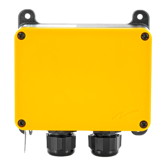
Page 12: Mechanical Installation
MECHANICAL INSTALLATION 120 mm (4.75 in) 102 mm (4.00 in) Cable diameter 6–13 mm (0.25–0.50 in) - 12 -... -
Page 13: Chapter 4: Users' Guide
Chapter 4: USERS' GUIDE CHAPTER 4: USERS' GUIDE RADIO MODE NOTE! The radio mode is determined by the selected Operating mode. To establish a radio link between the transmitter and receiver, both units need to be set to the same radio mode. ... -
Page 14: Operating Modes
OPERATING MODES Select Operating mode NOTE! Go to the Operating modes pages to see the Operating modes available when transmitting in continuous/discontinuous radio mode. Operating modes do not work for both radio modes. 1. Press the Function button 4 times. LED 10 lights (orange). - Page 15 OPERATING MODE 1 NOTE! Only for continuous radio mode. T17-12 T17-8 T19-2 step step step step step step step step step step step step 10 10 10 10 10 10 T13-3/6/8/10 T21-3/6/8/10 1 1 1 1 1 1 6 T7-14/15/16 1 1 1 1 1 1 10 1 1 1 1 1 1 6...
- Page 16 OPERATING MODE 2 NOTE! Only for continuous radio mode. T17-12 T17-8 T19-2 step step step step step step step step step step step step T13-3/6/8/10 T21-3/6/8/10 T7-14/15/16 1 1 1 1 1 1 2 1 1 1 1 1 1 2 ...
- Page 17 OPERATING MODE 3 NOTE! Only for continuous radio mode. T17-12 T17-8 T19-2 step step step step step step step step step step step step 10 10 11 11 10 10 11 11 10 10 11 11 T13-3/6/8/10 T21-3/6/8/10 1 1 1 1 1 1 6 T7-14/15/16 1 1 1 1 1 1 6...
- Page 18 OPERATING MODE 4 NOTE! Only for continuous radio mode. T17-12 T17-8 T19-2 step step step step step step step step step step step step 10 10 1111 10 10 1111 10 10 1111 T13-3/6/8/10 T21-3/6/8/10 1 1 1 1 1 1 3 T7-14/15/16 1 1 1 1 1 1 7 1 1 1 1 1 1 3...
- Page 19 OPERATING MODE 5 NOTE! Only for discontinuous radio mode. IMPORTANT! Discontinuous radio mode cancels the PLd safety classified stop function. T13-3/6/8/10 T19-2 T7-14/15/16 T21-3/6/8/10 1 1 1 1 1 1 3 1 1 1 1 1 1 3 1 1 1 1 1 1 7 1 1 1 1 1 1 7 step...
-
Page 20: Chapter 5: Guarantee, Service, Repairs And Maintenance
Tele Radio AB products are covered by a guarantee/warranty against material, construction and manufacturing faults. During the guarantee/warranty period, Tele Radio AB may replace the product or faulty parts. Work under guarantee/warranty must be carried out by Tele Radio AB or by an authorized service centre specified by Tele Radio AB. -
Page 21: Chapter 6: Regulatory Information
This product is in compliance with the essential requirements of directive 1995/5/EC of the European Parliament and of the Council. Latest version of the EC Declaration of Conformity can be downloaded from the Tele Radio AB website, www.tele-radio.com. - 21 -... -
Page 22: Chapter 7: Frequent Terms
Chapter 7: FREQUENT TERMS CHAPTER 7: FREQUENT TERMS Configuration ID Numerical code stored in both the transmitter and receiver unit. The receiver unit can only be controlled by a transmitter with the correct configuration ID. Continuous radio When in continuous radio mode the transmitter unit transmits continuously when mode it is switched on. - Page 23 Chapter 7: FREQUENT TERMS (This page has intentionally been left blank) - 23 -...
- Page 24 This installation instruction is subject to change without prior notice. Download the latest installation instruction from www.tele-radio.com...
Need help?
Do you have a question about the Panther PN-R15-1 and is the answer not in the manual?
Questions and answers