
Related Manuals for Tele Radio R2-01


Summary of Contents for Tele Radio R2-01
- Page 1 INSTALLATION INSTRUCTIONS Receiver R2-01 with transmitters T1-01, T1-02, T1-03 safe smart strong IM-LX-RX101-EN-v01 Language: English (original)
- Page 2 ©Tele Radio AB Datavägen 21 SE-436 32 Askim Sweden Phone: +46 (0)31 748 54 60...
-
Page 3: Table Of Contents
Installation instructions│ R2│ C O NT E NT S CHAPTER 1: INTRODUCTION 1.1 About this document 1.2 About Lynx systems CHAPTER 2: SAFETY 2.1 Warnings & restrictions CHAPTER 3: TECHNICAL DATA 3.1 Stationary unit specifications 3.2 Current consumption CHAPTER 4: PRODUCT GENERAL DESCRIPTION 4.1 Stationary unit description 4.2 Mechanical installation CHAPTER 5: BOARD DESCRIPTION 5.1 Base board... -
Page 4: Chapter 1: Introduction
These Installation instructions have been published by Tele Radio AB and are not subject to any guarantees. The Installation instructions may be withdrawn or revised by Tele Radio AB at any time and without further notice. Corrections and updates will be added to the latest version of the manual. Always download the Installation instructions from our website, www.tele-radio.com, for the latest... - Page 5 Tele Radio AB Installation instructions do not include or address the specific instructions and safety warnings of the end product manufacturer. Tele Radio AB products are covered by a warranty against material, construction, or manufacturing faults. See "Chapter 8: Warranty, service, repairs, and maintenance".
-
Page 6: About This Document
Installation instructions│ R2│ Chapter 1: Introduction 1 .1 A b o u t t h is do c u m en t Every care has been taken in the preparation of this manual. Please inform Tele Radio AB of any inaccuracies or omissions. These installation instructions cover general safety issues, main technical specifications, standard installation, configuration instructions and battery information. -
Page 7: About Lynx Systems
Installation instructions│ R2│ Chapter 1: Introduction 1 .2 A b o u t Ly n x s y s t em s Lynx systems are composed of a stationary unit (receiver), a hand unit (transmitter) and a master unit (PC). The communication between the master device and the Lynx system requires to write a software application. - Page 8 Installation instructions│ R2│ Chapter 1: Introduction 1 . 2 . 4 G E N E RA L I N F O RM A T I O N A B O UT M O D B US P RO T O C O L To enable communication between computerized systems, a protocol is required to define the rules of communication.
- Page 9 Installation instructions│ R2│ Chapter 1: Introduction 1 . 2 . 6 I N P UT S / O UT P UT S O p en c o l l ec t o r s ( O C ) A lower or higher voltage than the input power supply can be used (up to 24V DC). Can be used to interface devices that have different operating logic voltage levels, or to control external circuitry that requires a higher voltage level ( e.g.
-
Page 10: Chapter 2: Safety
IMPORTANT! Tele Radio AB remote controls are often built into wider applications. These systems should be equipped with: • a wired emergency stop where necessary ... - Page 11 Installation instructions│ R2│ Chapter 2: Safety RISK OF UNINTENDED EQUIPMENT OPERATION Only transmitters that are intended for use should be registered in the receiver. Failure to follow these instructions could result in death, serious injury, or equipment damage. RISK OF ELECTRIC SHOCK The receiver must only be opened by qualified installers or authorized personnel.
- Page 12 Installation instructions│ R2│ Chapter 2: Safety Make sure that the user satisfies the age requirements in your country for operating the equipment. Make sure that the user is not under the influence of drugs, alcohol and medications. Make sure that the user knows and follows operating and maintenance instructions as well as all applicable safety procedures and requirements.
-
Page 13: Chapter 3: Technical Data
Installation instructions│ R2│ Chapter 3: Technical data CHAP TER 3: TECHNICAL D ATA 3 .1 S t at io n ary u n it s p ec if ic at io n s R2-01 Power supply 5–24 V DC Number of digital inputs... -
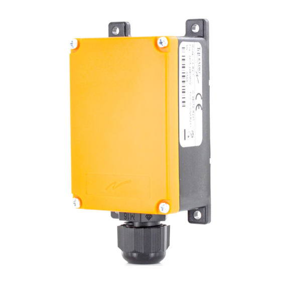
Page 14: Chapter 4: Product General Description
Installation instructions│ R2│ Chapter 4: Product general description CHAP TER 4: P RO D UCT G ENERAL DESCRIP TIO N NOTE: The pictures shown in this chapter are for illustrative purposes only. Depending on the configuration, the actual product appearance may differ from the basic model used for reference. -
Page 15: Mechanical Installation
Installation instructions│ R2│ Chapter 4: Product general description 4.2 M ec h an ic al in s t al l at io n IM-LX-RX101-EN-v01... - Page 16 Installation instructions│ R2│ Chapter 4: Product general description 4 . 2 . 1 I N S T A L L A T I O N P RE C A UT I O N S RISK OF ELECTRIC SHOCK The receiver must only be opened by qualified installers or authorized personnel.
-
Page 17: Chapter 5: Board Description
Installation instructions│ R2│ Chapter 5: Board description CHAP TER 5: BO ARD D ESCRIP TIO N NOTE: The pictures shown in this chapter are for illustrative purposes only. Depending on the configuration, the actual product appearance may differ from the basic model used for reference. RISK OF ELECTRIC SHOCK The receiver must only be opened by qualified installers or authorized personnel. - Page 18 Installation instructions│ R2│ Chapter 5: Board description 5 . 1 . 1 T E RM I N A L B L O C K F O R I N P UT P O W E R A N D C O M M UN I C A T I O N Pin ...
-
Page 19: Chapter 6: Status And Error Indications On The Stationary Unit
Installation instructions│ R2│ Chapter 6: Status and error indications on the stationary unit CHAP TER 6 : STATUS AND ERRO R IND ICATIO NS O N THE STATIO NARY UNIT ˜: LED is lit. ™: LED is off. ²: LED is blinking (red); : LED is blinking (yellow); LED 1 LED 2 LED 3... -
Page 20: Chapter 7: Hand Units
Installation instructions│ R2│ Chapter 7: Hand Units CHAP TER 7 : HAND UNITS 7 .1 Bat t ery p rec au t io n s Carefully read through the following safety instructions and warnings before using, charging or disposing of the batteries. Batteries contain flammable substances such as lithium or other organic solvents, which may result in overheating, rupture or combustion. - Page 21 Installation instructions│ R2│ Chapter 7: Hand Units 7 .2 Han d u n it des c rip t io n – T 1 - 0 1 , T 1 - 0 2 , T 1 - 0 3 T1-01 T1-02 T1-03...
- Page 22 Installation instructions│ R2│ Chapter 7: Hand Units 7 . 2 . 1 T E C H N I C A L D A T A T1-01, T1-02, T1-03 Power supply 2 x 1.5 V AAA alkaline battery Radio frequency band 2405–2480 MHz Number of channels 16 (channels 11–26)
-
Page 23: Change The Batteries
Installation instructions│ R2│ Chapter 7: Hand Units 7 .3 C h an ge t h e b at t eries BATTERY TYPE: 2 x 1.5 V AAA alkaline Do not recharge the batteries! Attempts to recharge the batteries may cause rupture, or leaking of hazardous liquids, which will corrode the equipment and result in minor or moderate injury. -
Page 24: Status And Error Indications On The Hand Unit
Installation instructions│ R2│ Chapter 7: Hand Units 7 .4 S t at u s an d erro r in dic at io n s o n t h e h an d u n it The Lynx system only controls the red/ green top LED 1 on the hand unit. The functions of LEDs 2–5 are determined by the design of the customer host system and are therefore not described here. -
Page 25: Chapter 8: Warranty, Service, Repairs, And Maintenance
Tele Radio AB products are covered by a warranty against material, construction and manufacturing faults. During the warranty period, Tele Radio AB may replace the product or faulty parts. Work under warranty must be performed by Tele Radio AB or by an authorized service center specified by Tele Radio AB. -
Page 26: Chapter 9: Regulatory Information
T1-01, T1-02, T1-03 9 . 1 . 1 C E M A RK I N G Hereby, Tele Radio AB, declares that the radio equipment type(s) listed above is/ are in compliance with Directive 2014/53/EU. The latest version of the complete EU Declaration of Conformity is available on the Tele Radio AB website, www.tele-radio.com. -
Page 27: North America
Applies to: Receiver Transmitters R2-01 T1-01, T1-02, T1-03 9 . 2 . 1 F C C S T A T E M E N T This device complies with part 15 of the FCC Rules. Operation is subject to the... - Page 28 Installation instructions│ R2│ Chapter 9: Regulatory information (2) This device must accept any interference, including interference that may cause undesired operation of device. Le présent appareil est conforme aux CNR d’Industrie Canada applicables aux appareils radio exempts de licence. L’exploitation est autorisée aux deux conditions suivantes : 1) l’appareil ne doit pas produire de brouillage;...
-
Page 29: Annex A: Implementation Specifications - Lynx (In English)
– Add one transmitter by ID 0x05 – Enter Learn mode 0x43 Tele Radio – Interrupt (Not implemented) 0x01 – Change interrupt A .2 Regis t er M ap Changes to registers will be applied directly after a Modbus response has been sent from the slave. - Page 30 Installation instructions│ R2│ Annex A: Implementation Specifications – Lynx (in English) Address Contents 0x0004 RS485 Modbus address (default 0x66 ) 0x0005 Radio channel (default 17) 0x0006 Functionality 0x0007 RS232 Baud rate 0x0008 RS232 Serial port mode 0x0009 RS485 Baud rate 0x000A RS485 Serial port mode ...
- Page 31 Installation instructions│ R2│ Annex A: Implementation Specifications – Lynx (in English) Contents 7–0 Radio Channel (11-29) (Default: 17) 15–8 Reserved A . 2 . 5 F UN C T I O N A L I T Y – 0 X 0 0 0 6 Contents 0 (LED Control) 0 = Respond To Event handles LEDs for specific units (Default)
- Page 32 Installation instructions│ R2│ Annex A: Implementation Specifications – Lynx (in English) Value Baudrate 57600 baud A . 2 . 9 RS 4 8 5 S E RI A L P O RT M O D E – 0 X 0 0 0 A Value Baudrate 0 (default)
- Page 33 Installation instructions│ R2│ Annex A: Implementation Specifications – Lynx (in English) A . 2 . 1 1 D I S C RE T E I N P UT S O N S T A T I O N A RY UN I T – 0 X 0 2 0 1 Contents 0 (Input 1) 0 = Not Active...
- Page 34 Installation instructions│ R2│ Annex A: Implementation Specifications – Lynx (in English) Contents 0 (Output 1) 0 = Not Active 1 = Active 1 (Output 2) 0 = Not Active 1 = Active 15–2 Reserved IM-LX-RX101-EN-v01...
-
Page 35: Annex B: Settings Documents
Installation instructions│ R2│ Annex B: Settings Documents ANNEX B: SETTING S DO CUM ENTS Rec eiver Article code: ___________________________________________________________ Serial no: ______________________________________________________________ Radio channel: _________________________________________________________ RS232 Modbus serial setting:_____________________________________________ RS485 Modbus serial setting:_____________________________________________ RS232 Modbus address:__________________________________________________ RS-485 Modbus address:_________________________________________________ T ran s m it t er 1 Article code: __________________________________________________________ Serial no: _____________________________________________________________ Radio channel: ________________________________________________________... -
Page 36: Annex C: Index
Installation instructions│ R2│ Annex C: Index ANNEX C: INDEX Boards Connector for digital inputs Current consumption Dimensions 13, 22 EIRP 13, 22 FCC/IC labels IC Statement Installation precautions IP code Maintenance Mounting dimensions Operating temperature 13, 22 Radio frequency band 2.4 GHz Frequency channels IM-LX-RX101-EN-v01... - Page 37 Installation instructions│ R2│ Annex C: Index Technical data R2-01 T1-01, T1-02, T1-03 Terminal block for input power and communicaion Warnings & restrictions Installation and commission Maintenance Operation WEEE directive Wiring example Digital inputs IM-LX-RX101-EN-v01...
- Page 38 safe smart strong These Installation instructions are subject to change without prior notice. Download the latest Installation instructions from www.tele-radio.com .
Need help?
Do you have a question about the R2-01 and is the answer not in the manual?
Questions and answers