Table of Contents
Advertisement
safe
smart
IM-T20T60-RX101-EN-v02
Language: English (original)
INSTALLATION
INSTRUCTIONS
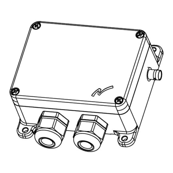
Receivers:
T20RX-02AKL
T20RX-02AKM
strong
With transmitters T20TX-01NKL, T20TX-02NKM , T20TX-02NKL,
T20TX-02NKM , T20TX-03NKL, T20TX-03NKM, T20TX-15DMM, T20TX-
15SMM; T60TX-0*STL, T60TX-0*STM, T60/T8-50, T60/T8-51, T60/T8-
52, T60/T8-53
T20RX-03ASL,
T20RX-03ASM
T 2 0
T 6 0
Advertisement
Table of Contents


Need help?
Do you have a question about the T20RX-02AKL and is the answer not in the manual?
Questions and answers