
Related Manuals for Tele Radio R20-01


Summary of Contents for Tele Radio R20-01
- Page 1 END USER INSTRUCTIONS Receivers: R20-01, R20-04 safe smart strong R 2 0 ED-PM-RX102-EN-v02 Language: English (original)
- Page 2 ©Tele Radio AB Datavägen 21 SE-436 32 Askim Sweden Phone: +46 (0)31 748 54 60...
-
Page 3: Table Of Contents
End user instructions│ R20│ CHAPTER 1: INTRODUCTION 1.1 About this document 1.2 About this system CHAPTER 2: SAFETY 2.1 Warnings & restrictions CHAPTER 3: FUNCTIONAL SAFETY CHAPTER 4: TECHNICAL DATA 4.1 System specifications 4.2 Receiver specifications 4.3 Current consumption CHAPTER 5: PRODUCT GENERAL DESCRIPTION 5.1 Receiver description CHAPTER 6: STATUS AND ERROR INDICATIONS 6.1 Receiver's Status code 6.2 CANopen (DLEDs ) run status 6.3 CANopen (DLEDs) error status 6.4 J1939 (DLEDs ) run status 6.5 J1939 (DLEDs) error status CHAPTER 7: OPERATION 7.1 General information 7.2 Register a transmitter in a receiver 7.3 Log all transmitters out with the receiver CHAPTER 8: BATTERY 8.1 Battery precautions 8.2 Battery information CHAPTER 9: WARRANTY, SERVICE, REPAIRS, AND MAINTENANCE CHAPTER 10: REGULATORY INFORMATION 10.1 Europe 10.2 North America 10.3 Radio module ANNEX 11: INDEX ED-PM-RX102-EN-v02... -
Page 4: Chapter 1: Introduction
End user instructions│ R20│ Chapter 1: Introduction CHAP TER 1 : INTRO D UCTIO N T h an k y o u f o r u s in g a T el e Radio A B p ro du c t READ ALL INSTRUCTIONS AND WARNINGS CAREFULLY BEFORE ... -
Page 5: About This Document
End user instructions│ R20│ Chapter 1: Introduction 1 .1 A b o u t t h is do c u m en t Before installing or operating the product, read the corresponding documentation carefully. Tele Radio AB's product range is composed of transmitters, receivers, and accessories intended for use together as a system. R20 systems are mainly intended for the hydraulic and mobile equipment markets. These systems are not standardized but customized and adapted to each customer's needs. How the outputs are connected to control the object depends on each specific installation and will not be covered in this document. For exact details, see the technical documentation provided for your specific system. Drawings, schematics and connection diagrams are unique and are also provided together with the system. Images shown in this document may therefore not show the exact position of buttons, paddles and are for illustrative purposes only. These End user instructions cover main technical specifications, standard o perating instructions. Please report any error or omission in this document, as well as any improvement or ... -
Page 6: About This System
Base 35 pins board RS485 A/D IOs 8-relay ● ● ○ ○ ○ ○ R20-01 ○ ● ○ ○ ○ ○ R20-04 ● ○ Standard Optional 1 . 2 . 3 C O M P A T I B I L I T Y This receiver is compatible with all transmitters and receivers in the Puma range. -
Page 7: Chap Ter 2: Safety
End user instructions│ R20│ Chapter 2: Safety CHAP TER 2: SAFETY 2 .1 W arn in gs & res t ric t io n s Carefully read through the following safety instructions before proceeding with the installation, configuration, operation, or maintenance of the product. Failure to follow these warnings could result in death or serious injury. This product must not be operated without having read and understood the End user instructions, the specific technical documentation (for customized systems), and having received the appropriate training. The purchaser of this product has been instructed how to handle the system safely. The following information is intended for use as a complement to applicable local regulations and standards. IMPORTANT! Tele Radio AB remote controls are often built into wider applications. These systems should be equipped with: • a wired emergency stop where necessary • a brake • an audible or visual warning signal 2 . - Page 8 End user instructions│ R20│ Chapter 2: Safety Always follow operating and maintenance instructions as well as all applicable safety procedures and requirements. Do not open the receiver encapsulation unless you are qualified. You must satisfy the age requirements in your country for operating the equipment. It is strictly prohibited to operate the equipment under the influence of drugs, alcohol and/or medications. Always test the transmitter stop button b efore operating it. Press the stop button then twist and pull it out. This test should be done on each shift, without a load. Never use a transmitter if the stop button is mechanically damaged.Contact your supervisor or representative for service immediately. Never leave the transmitter unattended. Always switch the transmitter off when not in use. Store in a safe place. Keep a clear view of the work area at all times. 2 . 1 . 2 M A I N T E N A N C E Before maintenance intervention on any remote controlled equipments: • always remove all electrical power from the equipment.
- Page 9 End user instructions│ R20│ Chapter 2: Safety Wipe off dust using a clean, slightly dam cloth. Never use cleaning solutions. Check the encapsulation, foils and cable for damages every day. If you use the product although the encapsulation or foil is damaged, moisture can cause serious damage to the electronics. ED-PM-RX102-EN-v02...
-
Page 10: Chap Ter 3: Functio Nal Safety
End user instructions│ R20│ Chapter 3: Functional safety CHAP TER 3: FUNCTIO NAL SAFETY S t o p f u n c t io n The safety-related stop function in the radio system complies with EN IEC 61508:2010 SIL3 and EN ISO 13849-1:2015 Category 3 PL e. The stop relays on the receiver unit are controlled by the stop button on the transmitter unit. When the stop button is pressed, the stop relays interrupt the power to the safety-related application. The complete end user system, including the radio system, enters a safe state. The default response time for the stop function is 500 ms. The stop function is supported by all receivers and t ransmitters in the Puma range. A p p l ic ab l e p ro du c t s The following transmitters are designed to comply with the appointed safety ... - Page 11 End user instructions│ R20│ Chapter 3: Functional safety M eas u res f o r p ro b ab il it y o f h ardw are f ail u res Measure System based on… T24 + R20 T24 + R21 Probability of dangerous failure per ...
-
Page 12: Chap Ter 4: Technical Data
End user instructions│ R20│ Chapter 4: Technical data CHAP TER 4: TECHNICAL DATA NOTE: The information below may differ in customized systems, p lease refer to the corresponding technical documentation provided with each system. 4.1 S y s t em s p ec if ic at io n s Radio frequency band 2405 – 2480 MHz Frequency management Direct Sequence Spread Spectrum (DSSS) Field Strength Adaptation Feature Number of Channels 16 (channel 11 – 26) Range (typical) 100 m (328 ft), adjustable depending on configuration System address... - Page 13 End user instructions│ R20│ Chapter 4: Technical data Number of logical digital up to 4 inputs Number of logical digital up to 2 outputs Max. number of 26 (6 SIO + 20 PWM) selectable & combinable I/Os on base board Number of Safe I/Os up to 7 x 10 A Number of PWM I/Os up to 20 x 4 A Bus system/ com. protocols standard: –...
-
Page 14: Current Consumption
● ○ Standard Optional – : Not available 4.3 C u rren t c o n s u m p t io n The test was performed with only the base and bottom boards . The t est was performed with only the base board a nd one CAN board .The same settings were applied on all the PWM outputs of the base board. Input power R20-01, R20-04 Min.* Max.** 12 V DC 112 mA 333 mA 24 V DC 65 mA 233 mA *Minimum current consumption = receiver powered, no active relays and/or outputs, no ... -
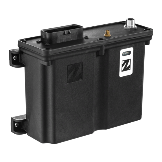
Page 15: Chapter 5: Product General Description
End user instructions│ R20│ Chapter 5: Product general description CHAP TER 5: P RO D UCT G ENERAL D ESCRIP TIO N NOTE: The pictures shown in this chapter are for illustrative purposes only. Depending on the configuration, the actual product appearance may differ from the basic model used for reference. 5 .1 Rec eiver des c rip t io n 1. LED 2. Capacitive sensor button (Cap 3. ... - Page 16 End user instructions│ R20│ Chapter 5: Product general description 1. Status LEDs 1–5: LED 1 (red): Registered transmitter and radio link status LED 2 (yellow): Transmitter login status LED 3 (green): Not used LED 4 (orange): Not used LED 5 (blue): Bluetooth connection status 2. CAN status LEDs DLED 1: CAN interface 1 (in option) DLED 2: Not used 3. Capacitive sensor button (Cap sensor button) 5 . 1 . 2 M O UN T I N G D I M E N S I O N S NOTE: For cable glands and cable diameter used in customized systems, please refer ...
-
Page 17: Chapter 6: Status And Error Indications
End user instructions│ R20│ Chapter 6: Status and error indications CHAP TER 6 : STATUS AND ERRO R IND ICATIO NS 6.1 Rec eiver's S t at u s c o de LEDs 1–5 indicate errors and status for the receiver, DLEDs 1–2 indicate errors and status for CANopen. Color Flashing Indicates ● ... -
Page 18: Canopen (Dleds) Error Status
End user instructions│ R20│ Chapter 6: Status and error indications CANopen Description communication state Operational State for process data transmission. LSS services in progress. Stopped Except for node guarding or heartbeat messages, a node cannot transmit or receive any other messages in this state. Pre-operational State for the configuration of CANopen devices. PDO communication is not possible in this state. 6.3 C A No p en ( DLE D s ) erro r s t at u s DLED Flickering (red/ Single flash... -
Page 19: Chapter 7: Operation
End user instructions│ R20│ Chapter 7: Operation CHAP TER 7 : O P ERATIO N 7 .1 G en eral in f o rm at io n To control a receiver, the transmitter must be registered and logged in to the receiver. If another transmitter is already logged in to the receiver, it must be logged out before a different transmitter can be logged in. More than one transmitter can be registered in the receiver, but only one transmitter can be logged in at a time. 7 .2 Regis t er a t ran s m it t er in a rec eiver Registering means establishing communication between the transmitter and the receiver. - Page 20 End user instructions│ R20│ Chapter 7: Operation On the Receiver On the Transmitter 4. Make sure that the Stop button is pressed. 5. Turn the key switch to the 'On' position (horizontal). 6. Twist and release the Stop button. The initial start-up logo is displayed.Battery indicator(s) light 1. Power the receiver up. (s).The display shows: [Session Selection] LED 1 is flashing (red) . If Bluetooth 7. Enter Menu mode(see corresponding has been activated, the LED 5 will transmitter's manual). also flash (blue). 8. Navigate to the menu [Register] 2. Press and hold the Cap sensor using t he Up/Down buttons. button until LED1 stops flashing. 9. ...
-
Page 21: Log All Transmitters Out With The Receiver
End user instructions│ R20│ Chapter 7: Operation On the Receiver On the Transmitter LED 1 i s flashing (slow). The transmitter turns off. If not successfully completed: On the Receiver On the Transmitter The receiver exits registration mode. The display shows: [Registration LED 1 is flashing (red). If Bluetooth has . The transmitter turns off. failed Timout] been activated, the LED 5 will also flash Go back and proceed from step 2. (blue). ... -
Page 22: Chap Ter 8: Battery
End user instructions│ R20│ Chapter 8: Battery CHAP TER 8: BATTERY 8 .1 Bat t ery p rec au t io n s Carefully read the following safety instructions and warnings before using or disposing of the batteries. Batteries contain flammable substances such as lithium or other organic solvents, which may result in overheating, rupture or combustion. Failure to read and follow the below instructions may result in fire, personal injury and damage to property if charged or used improperly. 8 . 1 . 1 H A N D L I N G A N D S T O RA G E ... -
Page 23: Battery Information
End user instructions│ R20│ Chapter 8: Battery 8 .2 Bat t ery in f o rm at io n Keep batteries out of reach of small children. Should a child swallow a battery, consult a physician immediately. R20 receivers are equipped with one button cell for clock backup in case of a main power failure. If the button battery is drained when a main power failure occurs, the time indicator w ill show the default date and time. Default date and time will also be used by the real time log. BATTERY Article number CR2032 Battery type Non-rechargeable, replaceable, lithium battery Weight (typical) 3 g (0.10 oz) Voltage 3 V / ~220 mAh Service life ~ 750 h @20 °C 15k load Self-discharge ~1–2% / year NOTE: Electronics and batteries must be physically separated before disposal. Make ... -
Page 24: Chap Ter 9 : Warranty, Service, Rep Airs, Andm Aintenance
End user instructions│ R20│ Chapter 9: Warranty, service, repairs, and maintenance CHAP TER 9 : WARRANTY, SERVICE, REP AIRS, AND M AINTENANCE Tele Radio AB products are covered by a warranty against material, construction and manufacturing faults. During the warranty period, Tele Radio AB may replace the product or faulty parts. Work under warranty must be performed by Tele Radio AB or by an authorized service center specified by Tele Radio AB. The following are not covered by the warranty: Faults resulting from normal wear and tear Parts of a consumable nature Products that have been subject to unauthorized modifications Faults resulting from incorrect installation and use Damp and water damage M ain t en an c e ... -
Page 25: Chapter 10: Regulatory Information
CHAP TER 1 0: REG UL ATO RY INFO RM ATIO N NOTE: Models including additional naming conventions: Model Article names Additional naming conventions R20-01, R20-… HY-R20 HY-R21, HY-R20-… 1 0 .1 E u ro p e Applies to: ... - Page 26 End user instructions│ R20│ Chapter 10: Regulatory information (2) this device must accept any interference received, including interference that may cause undesired operation. Changes or modifications not expressly approved by the party responsible for compliance could void the user’s authority to operate the equipment. This equipment has been tested and found to comply with the limits for a Class B digital device, pursuant to part 15 of the FCC Rules. These limits are designed to provide reasonable protection against harmful interference in a residential installation. This equipment generates uses and can radiate radio frequency energy and, if not installed and used in accordance with the instructions, may cause harmful interference to radio communications. However there is no guarantee that interference will not occur in a particular installation. If this equipment does cause harmful interference to radio or television reception, which can be determined by turning the equipment off and on, the user is encouraged to try to correct the interference by one or more of the following measures: Reorient or relocate the receiving antenna. Increase the separation between the equipment and receiver. Connect the equipment into an outlet on a circuit different from that to which the receiver is connected. Consult the dealer or an experienced radio/TV technician for help. To satisfy FCC RF exposure requirements, a separation distance of 20 cm or more should be maintained between the antenna of this device and persons during device operation. To ensure compliance, operations at closer than this distance is not recommended. 1 0 . 2 . 2 I C S T A T E M E N T This product complies with Industry Canada's licence-exempt RSSs. Operation is subject ...
- Page 27 End user instructions│ R20│ Chapter 10: Regulatory information This radio transmitter has been approved by Industry Canada to operate with the antenna types listed below with the maximum permissible gain and required antenna impedance for each antenna type indicated. Antenna types not included in this list, having a gain greater than the maximum gain indicated for that type, are strictly prohibited for use with this device. Gain of antenna: 3.0 dBi max. Type of antenna: 50 ohm, Omni-directional Le présent émetteur radio a été approuvé par Industrie Canada pour fonctionner avec les types d'antenne énumérés ci-dessous ayant le g ain admissible maximal et l'impédance requise pour chaque type d'antenne indiqué. Les types d'antenne non inclus dans cette liste, ou dont le gain est supérieur au gain maximal indiqué, sont strictement interdits pour l'exploitation de l'émetteur. Gain d'antenne: 3.0 dBi maximum Type d'antenne: 50 ohm, omnidirectionnel To satisfy IC RF exposure requirements, a separation distance of 20 cm or more should be maintained between the antenna of this device and persons during device operation. To ensure compliance, operation at closer than this distance is not recommended. Afin d'assurer la conformité aux exigences de la IC en matière d'exposition aux RF, une distance de séparation d'au moins 20 cm doit être maintenue entre l'antenne de cet appareil et toute personne à proximité pendant le fonctionnement de l'appareil. Pour assurer le respect de ces exigences, il n'est pas recommandé d'utiliser l'appareil à une distance inférieure à celle-ci. 1 0 . 2 . 3 F C C / I C L A B E L S The radio module in this product is labeled with its own FCC ID and IC numbers. The FCC ...
-
Page 28: Radio Module
End user instructions│ R20│ Chapter 10: Regulatory information 1 0 .3 Radio m o du l e The products described in these instructions contain the radio modules: PRODUCT RADIO MODULE D00005-15 ED-PM-RX102-EN-v02... -
Page 29: Annex 11: Index
End user instructions│ R20│ Annex 11: Index ANNEX 1 1 : IND EX About R20 receivers Antenna Battery Battery precautions Handling Storage Bus system Compatibility Current consumption Data format Disposal EIRP Error indications CANopen J1939 FCC statement FCC/IC labels Frequency management IC Statement ED-PM-RX102-EN-v02... - Page 30 End user instructions│ R20│ Annex 11: Index IP code LED indicators 15, 17 Log out Logical digital inputs Logical digital outputs Logout Maintenance Mounting dimensions Receiver Multi-function inputs/outputs Number of channels Operating temperature Operating voltage Power supply PWM inputs/outputs Radio communication Radio frequency band Radio frequency output power Radio module Range Register ED-PM-RX102-EN-v02...
- Page 31 End user instructions│ R20│ Annex 11: Index Safe inputs/outputs Safety standards Specifications Other specifications Receiver System Status and error code messages Status indications CANopen J1939 Receiver Storage temperature System address System number Warnings & restrictions Maintenance Operation WEEE directive ED-PM-RX102-EN-v02...
- Page 32 safe smart strong These End user instructions are subject to change without prior notice. Download the latest End user instructions from www.tele-radio.com .
Need help?
Do you have a question about the R20-01 and is the answer not in the manual?
Questions and answers