Table of Contents
Advertisement
Quick Links
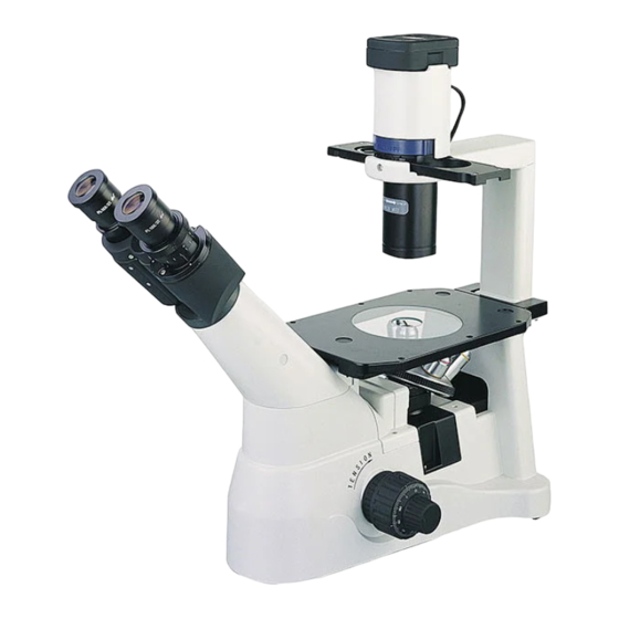
Inverted Microscope
Instructions
This instruction manual is for the Invert microscope XD series. To ensure the safety
and obtain optimum performance and to familiarize yourself fully with use of this
microscope, we recommend that you study this manual thoroughly before operating the
microscope. Retain this instruction manual in an easily accessible place near the work desk
for future reference.
1
Advertisement
Table of Contents

Related Manuals for OPTO-EDU XD Series


Summary of Contents for OPTO-EDU XD Series
- Page 1 Inverted Microscope Instructions This instruction manual is for the Invert microscope XD series. To ensure the safety and obtain optimum performance and to familiarize yourself fully with use of this microscope, we recommend that you study this manual thoroughly before operating the microscope.
-
Page 2: Table Of Contents
Contents INSTRUCTION 1. Nomenclature ……………………………………………………………………………….1 2. Assembling ……………………………………………………………………………………3 2-1.Assembling scheme.……………………………………………………………………..3 2-2.Assembling step…………………………………………………………………………4 Adjusting Device………………………………………………………………………...……..8 Using Adjusting Device………………………………………………………………...…...…10 4-1.Stand……………………………………………………………………………………..10 4-2.Stage……….……………………………………………………………………………11 4-3.Observing Tube…………………………………………………………………………12 4-4.Illumination device...……………………………………………………………………14 5.Phase-contrast Observation………………………………………………………………16 … 5-1. Nomenclature …………………..……………………………………………………16 5-2Assembling and operating………………………………………………………………17 6.TV device & Photography device ……………………………………………………….19 6-1. TV device………..…………………………………………………………………..…19 6-2.... - Page 3 Before Using ⅠNotice 1. Do not let the microscope emerge in the sun directly, either not in the high temperature, damp, dusty or acute shake place. Make sure the worktable is horizontal and hard enough. [Weight: about 9 KG(19.8 P), about 9.6 KG(21.2 P).] 2.
- Page 4 Before Using Ⅲ Safety Sign Sign Signification It shows the surface gets hot and don’t touch with bare hand. Read the introduction before use. Unsuitable operation would lead to person hurt or instrument faulty. Main switch ON ○ Main switch OFF...
-
Page 5: 1. Nomenclature
1. Nomenclature Lamp Holder XDAL2 Objectives ● LWDPL4× Illumination holder (fixed) ● LWDPL10× ● LWDPL20× ● LWDPL40× ● LWDPL60× ● LWDPH10× ● LWDPH20× ● LWDPH40× Phase-contrast slider ● Phase center presetting slider (XDSLP) ● Phase center adjustable slider (XDSL) Eyepiece ●... - Page 6 Lamp holder XDAL2 Objective Illumination holder (fixed) ● LWDPL4× ● LWDPL10× ● LWDPL20× ● LWDPL40× ● LWDPL60× ● LWDPH10× ● LWDPH20× ● LWDPH40× Phase-contrast slider ● Phase center presetting slider (XDSLP) ● Phase center adjustable slider (XDSL) Eyepiece Long work distance condenser ●...
-
Page 7: Assembling
2. Assembling Assembling scheme Numbers denote the assembling order. ★ Before assembling, make sure there is no dust or dirt. Assemble carefully and do not scrap any part or touch the glass face. ★ Preserve the hexagon spanner, and it will be used when changing the parts. Halogen Bulb 6V 30W HAL ①... -
Page 8: Assembling Step
Assembling step 2-2-1 Assemble and change the bulb (See fig.3) ◎ Lamp selected only: 6V/30W HAL bulb (Philips 5761) ★ Don’t touch the bulb with finger. If there is a fingerprint, wipe it with clean and soft cloth. Hold the bulb ① with clean glove or gauze and insert the pins ②... - Page 9 2-2-4 Assemble the objectives (See fig.6&fig.7) Rotate the coarse focusing knob ① , until the condenser is in low-limit location.(See fig.6) ★ The condenser is set to the lowest location when exworks, to make the instrument safe in transit. Please turn the adjusting ring② of the coarse adjustment knob to the proper tension.
- Page 10 2-2-6 Circular central stage (See fig.9) Assemble the metal stage① on the stage aperture. ◎ Turn the metal stage to face V② to the user. It is easy to make sure the objective. Just lay glass stage flat when using it. There is special direction.
- Page 11 2-2-9 Connect power wire (See fig.12, fig.13& fig. 14) ★ Do not exert force to power wire. It is easy to damage by twisting it. Turn the power switch to “O” ① (OFF) before connect the power wire. (See fig.12) Insert the plug②...
-
Page 12: Adjusting Device
3. Adjustment device ★ The adjustment ring for adjusting coarse tension is on the right of the equipment. See XD30 for its location. ★ Phase-contrast slide adopt phase center adjustable slide configured with phase center presetting rod. Phase-contract slider Diopter adjusting ring The adjusting ring of aperture diaphragm Color filter holder... - Page 13 ★ The power switch and Light adjustment button is on the left of the equipment. See XD20 for their location. Color filter holder Phase-contract slider The adjusting ring of aperture diaphragm Interpupillary distance pointer Phase center adjusting rod Diopter adjusting ring Light path shifting block Fine focusing knob Coarse focusing knob...
-
Page 14: Using Adjusting Device
4. Using adjusting device 4-1 Stand 4-1-1 Turn on the light (See fig.15) Connect the power wire, turn on the main switch① to “ — ” (on) . Fig 15 4-1-2 Adjust brightness (See fig.16) Turn the button in clockwise to brighten the light, and turn in anticlockwise to darken it. -
Page 15: Stage
4-2 Stage 4-2-1 Place sample (See fig.18&fig.19) Place the sample in the center of the stage. ★ Please select the container like Petri dish, culture flask etc, with the thickness of 1.5mm to get the best observe effects. Select specimen slide with the thickness of 1.5mm when place the sample on it. -
Page 16: Observing Tube
4-3 Observing tube 4-3-1 Adjust diopter (See fig.20&fig.21) ◎ 1. Turn coarse focusing knob and fine focusing knob to focus the specimen when observing the left eyepiece with left eye. 2. Then rotate the diopter adjustment ring① if the image is unclear when observing the right eyepiece with right eye.(See fig.20) ★... - Page 17 4-3-3 Use the eye-cap (See fig.23) If the customer wears glasses, turn over the eye-cap①. It can prevent the glasses touching the eyepiece and avoid damaging the glasses and the eyepiece. 2. If the customer doesn’t wear glasses, open the eye-cap②.
-
Page 18: Illumination Device
4-4 Illumination device 4-4-1 Use color filter ◎ Use color filter to increase the accuracy of the observation and photomicrography. Suggest user to adopt LBD color filter to get more neutral hue when observing bright-field and taking photo. ◎ Color filters could overlay on the filter holder, make sure lay them level, and the maximum of the thickness is 11mm. - Page 19 4-4-3 Shift the condenser lens away (See fig.26) ◎ Turn the parts① below the condenser in clockwise to get larger operation space. It could get the height of 150mm. ★ Remember it would not get well illumination when operating. It only proper to use big Petri dish when shift away the condenser.
-
Page 20: Phase-Contrast Observation
5. Phase-contrast observation 5-1 Nomenclature 5-1-1 Phase-contrast objective ◎ Magnification: 10X, 20X, 40X. ◎ Replace the objectives with phase-contrast objectives as 2-2-4 5-1-2 XDSLP phase-contrast slider (See fig.27) ◎ Phase center presetting slider ● Light loop center is preset, it no longer have need of adjustment. -
Page 21: 5-2Assembling And Operating
Assembling and operating 5-2-1 Assemble phase-contrast slider (See fig.29) 1. Place phase-contrast slider① upward (on letters side), insert it into the illumination holder from the right to the left. 2. Each diaphragm has its corresponding part. Enter the diaphragm into optical way by shifting the phase-contrast until hearing a click. - Page 22 ★ If the light loop is not centered, the user will not get the best effect of phase-contrast observation. ★ Overlay the phase loop onto the most bright image when seeing double light loop. ★ Light loop will deviate away from phase loop after moving or replacing a piece of thick specimen.
-
Page 23: Tv Device & Photography Device
6. TV device & Photography device TV device 6-1-1 Choosing the optical way (See fig.32) ★ Only adapt to trinocular head. 1. Move the block① for optical way shifting as the figure shows. 2. Move it until hearing a click. ★... -
Page 24: Photography Device
Photography device 6-2-1 Choosing the optical way ★ Only adapt to trinocular head. See 6-1-1 and 4-3-4 for details. 6-2-2 Assemble the Photography device (See fig.36) Loosen the lock-screw①on the trinocular head and get down the dust-cover②of the trinocular. (See fig.35) 2. - Page 25 6-2-3 Focus Set 20% of brightness to doing binocular observation, and focusing it. Focus the specimen by view finder when taking photo. camera assembly parts for instructions of the details. 6-2-4 Adjust color temperature ◎ Use daylight type film to take photo 1.
-
Page 26: Specification
7. Specification 7-1 Specification Optical system Color corrected infinity optical system (CSIS) Gemel type of binocular head, 45° inclined, Gemel type of trinocular head, 45° inclined, Head light splitting rate: binocular 100%, binocular 20%/ trinocular 80%, (interpupillary distance range:50-76mm) Eyepiece PL10X high-eye point plan eyepiece, line field 22mm Nosepiece Reversed quintuple nosepiece... -
Page 27: Troubleshooting
8. Trouble Shooting Reference Problem Cause Remedy page Optics Lamp base is not connect to Connect it correctly and firmly illumination device The bulb is burn out Replace it with new one 1. The bulb lightening The light adjust button turned to but it is dark in Adjust to proper brightness dark end... - Page 28 Reference Problem Cause Remedy page Interpupillary distance is wrong Adjust the interpupillary distance 6. The eyes feel tired Diopter adjustment is wrong Adjust the diopter easily. The right field of view Do not goggle at the specimen doesn’t overlay Eye not accustomed to when observing.
Need help?
Do you have a question about the XD Series and is the answer not in the manual?
Questions and answers