
Related Manuals for OPTO-EDU A16.2615-L


Summary of Contents for OPTO-EDU A16.2615-L
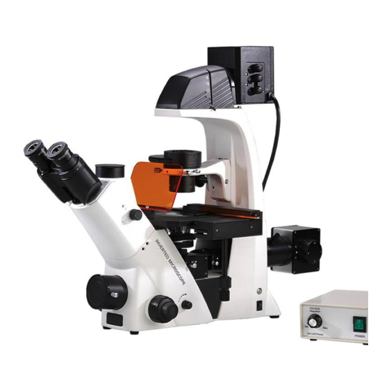
- Page 1 A16.2615-L Inverted LED Fluorescent Microscope Instruction Manual To ensure the safety and obtain satisfactory performance, please study this instruction manual thoroughly be fore start to use the instrument.
-
Page 2: Attentions
ATTENTIONS 1. Please clean sample-touching part after using. Following the Fig.1 step to move the instrument, make sure the sample is taken away. Use one hand holding ①position,the other hand holding② position. Once the sample is damaged, must take steps to avoid pollution. ... - Page 3 9. Don’t open microscope lower plate when in use or else exposed electrical element will lead to electric shock. Before replacing the lamp or fuse, please turn off power switch and pull out the plug from the socket. 10. Do not use alcohol, gasoline, paper and other combustibles near the instrument, to prevent fire ! ! Safety Mark MEANING...
-
Page 4: Table Of Contents
CONTENTS Attentions ............................1 1. Parts Name ............................4 2. Observation Steps ..........................6 3. Operation ............................7 3.1 Main Body ............................7 3.1.1 Turn On Light Source ........................7 3.1.2 Aperture Diaphragm ........................7 3.1.3 Adjustment of Field Diaphragm and Lamp Filament ..............7 3.1.4 Usage of Filter .......................... -
Page 5: Parts Name
1. Parts Name Fig.3 Main Parts Name 1) Eyepiece 2) Seidentopf Trinocular Head 3) Main Body 4) Adaptor for DSLR Camera 5) Coaxial Coarse and Fine Focusing Knob 6) Nosepiece 7) Attached Mechanical Stage 8) Fixed Stage 9) Turnable Phase Contrast Condenser 10)... - Page 6 Fig.4 Control Parts 1) Lamp House 2) Turnable Phase Contrast Condenser 15) Trinocular Switch Lever 3) Liftable Knob for Turnable Phase Contrast Condenser 16) Seidentopf Trinocular Head 4) Fixed Stage 17) Aperture Diaphragm Lever 5) Objective 18) Eyepiece 19) Fastening Screw for Lamphouse 6)...
-
Page 7: Observation Steps
Please read chapter 6 about assembly steps. Observation Steps Turn on main power source Place sample Put 10X objective in optical path Focusing sample Adjusting brightness Adjusting interpupilary distance and diopter Adjusting lamp filament position Putting objective in optical path and focusing field diaphragm Adjusting aperture diaphragm... -
Page 8: Operation
3. Operation 3.1 Main Body 3.1.1 Turn On Light Source (Fig.5) Turn potentiometer knob② to the minimum, turn on power switch to①position I (ON). Rotating potentiometer knob② to increase and decrease brightness for good illumination . ○ 4 to open infrared sensors switch,if you leaving the Infrared sensors Push button window for 10 minutes , it will be off automatically. -
Page 9: Usage Of Filter
○ c. Adjust centring screw to make field diaphragm coincide with field , fasten the 3 (Fig.6) ○ thumb screw ,adjust field diaphragm to make image edge 4 (Fig.6) ○ ○ ○ d. Adjust lamphouse knobs to make lamp filament image in the centre of 4 (Fig.7) aperture diaphragm, keep left right image in symmetry. -
Page 10: Adjustment Of Diopter
Fig.9 Adjustment of Interpupilary Distance Fig.10 Adjustment Of Diopter 3.3.2 Adjustment of Diopter (Fig.10) Please turn adjusting ring scale 0 to scale line at the first use. a. With right eye to observation by right eyepiece, focusing the sample by coarse and fine focusing knob . -
Page 11: Mechanical Stage
3.4.2 Mechanical Stage Mechanical stage can be moved freely at X and Y direction. ○ b. Insert standard stage round plate 1 in stage.(also don’t insert round plate as needed). ○ ○ c. Install attached mechanical stage in stage with knurled screw 3 or hexagon socket cap screws. -
Page 12: Fluorescence Attachment
3.6 Fluorescence Attachment ◎ A16.2615 inverted biological microscope can configured with fluorescence attachment(lamp house, power supply etc.) 3.6.1 Mechanism of Fluorescence Production Ultraviolet(U), Violet(V), Blue(B), Green(G) transmittance characteristic curve. UV ( Ultraviolet )Excitation V (Violet) Excitation B( Blue Light )Excitation G (Green Light )Excitation Fluorescence is a kind of photoluminescence in natural world. - Page 13 greater than 490 nm light through color spectroscope to be removed, and the excitation under 490 nm light irradiation by fluorescence objective can converge on the fluorescent specimens, specimen inspire greater than 490 nm wavelength of fluorescence(effective fluorescence wavelength of 525nm) and fluorescence imaging by objective gathering, and through the color spectroscope (with a small amount of under 490 nm exciting light is reflected back to the light source and not through) and cut-off filter (cutoff wavelength less than 525 nm light), pure fluorescent light beam for observation and photography.
-
Page 14: Parts Name
3.6.2 Parts Name Fig. 15 Fluorescence Parts Name 1) Eyepiece 2) Trinocular Switch knob 3) Main Body 4) Adaptor for DSLR Camera 5) Fastening Screw for DSLR Camera Adaptor 6) Infrared Sensors Indicator 7)Coarse & Fine Focusing Knobs 8) Potentiometer Knob 9)Fluorescent Transforming Handle 10) Diaphragm Slider 11) Mechanical Stage Hand Knob... -
Page 15: Mercury Lamp Power House
be moved into light path . ● Adjusting coarse and fine focusing knob to get clear image. ● Adjusting the center of the low and high pressure mercury lamp. After getting clear image by focusing , using condenser axial adjustment knob, mercury lamp arc light can be seen in the eyepiece . -
Page 16: Replacement Of Mercury Bulb
Fig.18 Front Side Fig.19 Back Side 1) Timer 2) Reset 3) Trigger Switch 4) Power Switch 5) Output Socket 6) Cooling Fan 7) Voltage Transfer Switch 8) Input Power Plug 9) Fuse Holder 3.6.5 Replacement of Mercury Bulb Cut off the power supply, with inner hexagon screwdriver to adjust the socket head screw which in the rear of the mercury lamp light box , then slowly remove the... -
Page 17: Replacement Of Mercury Lamp Fuse
3.6.6 Replacement of Mercury Lamp Fuse Turn off the power, pull out the plug and open fuse box . Mercury power supply fuse: Φ5×20mm,5.0A, 250V (The detail steps are as follows). Fig.21 Replacement Of Fuse Tube... -
Page 18: Trouble Shooting
加装机械载物台 4. Trouble Shooting Trouble Causation Remedy 1. Optical System Readjust nosepiece in right Nosepiece not in right location. position. a. Field incomplete or Filter slider not in right place. Readjust filter slider illumination irregular. Phase Contrast Slider aren’t moved out of optical path. Moving out the slider. -
Page 19: Installation
5. Installation 5.1 Installation Diagram Fig. 21 ○ ○ ○ ○ a Centring Telescope b Eyepiece c C-mount d Filters ○ ○ ○ e Turnable Phase Contrast Condenser f Halogen Lamphouse g Clamps ○ ○ ○ ○ ○ h Stage Round plate k Culture Dish Holder Blood Cell Counter Holder ○... -
Page 20: Installation Steps
5.2 Installation Steps 5.2.1 Installation And Replacement of Bulb (Fig.2 ,Fig.4) WARNING Cut off the power line plug before replace bulb Completely loosening screw on the top of the lamp house, pulling out lamp shade. Loosening bulb pins locking screw , using glove or gauze to hold the bulb and insert fully into the socket . -
Page 21: Installation Of Turnable Phase Contrast Condenser
5.2.4 Installation Of Turnable Phase Contrast Condenser a.Put phase contrast condenser into the holder(Fig.24), positioning screw○ must aim at relevant hole in connecting plate. Fig.24 Phase Contrast Installation ○ 1 Hexagonal Screwdriver ○ 2 Adjusting Screw Hole ○ 3 Filters ○... -
Page 22: Dslr Camera System(Optional)
Please read operation manual about usage of digital camera and circuit connection. 5.2.5.2 DSLR Camera System (Optional) ○ ○ Firstly, remove the camera lens and connect the DSLR camera 1 with interface 2 ,ensure install in good place. ○ Then gently connect DSLR camera 1 with adaptor ,rotating to suitable angle , then tightening ○... - Page 23 Inverted Biological Microscope A16.2615-L...
Need help?
Do you have a question about the A16.2615-L and is the answer not in the manual?
Questions and answers