Table of Contents
Advertisement
Quick Links
Version:V1.0
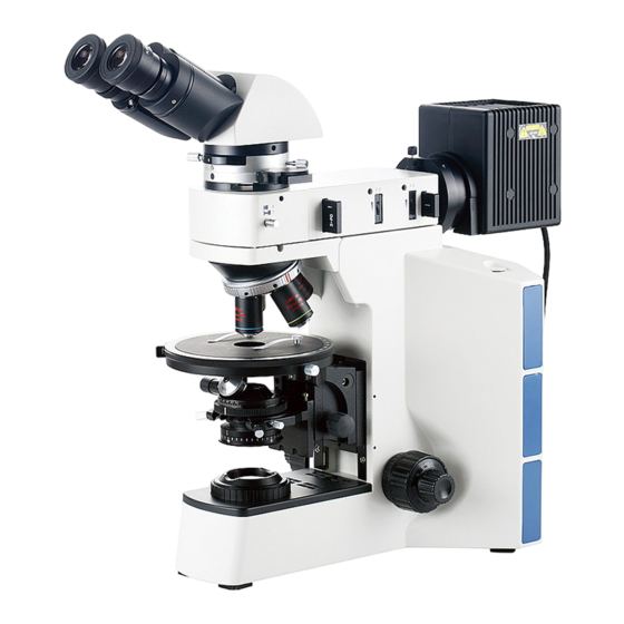
A15.0908 Series
Polarizing Microscope
INSTRUCTIONS
This instruction manual is for the operation guide, troubleshooting and
maintenance to the A15.0908 Series Polarizing Microscope. Please study this
manual thoroughly before operating, and keep it with the instrument. The
manufacturer reserves the rights to the modifications by technology
development. On the basis of operation ensured, technical specifications
may be subject to changes without notice.
Advertisement
Table of Contents

Related Manuals for OPTO-EDU A15 0908 Series


Summary of Contents for OPTO-EDU A15 0908 Series
- Page 1 Version:V1.0 A15.0908 Series Polarizing Microscope INSTRUCTIONS This instruction manual is for the operation guide, troubleshooting and maintenance to the A15.0908 Series Polarizing Microscope. Please study this manual thoroughly before operating, and keep it with the instrument. The manufacturer reserves the rights to the modifications by technology development.
-
Page 2: Table Of Contents
Contents A15.0908 Series Before Use 1. Components..........................1 2. Assembling ..........................3 2-1 Assembling Scheme......................3 2-2 Assembling Steps......................4 3. Operation ..........................8 3-1 Set Illuminations ......................8 3-2 Adjust Focusing ......................9 3-3 Adjust the Focusing Tension ................... 9 3-4 Adjust the Diopter ...................... -
Page 3: Before Use
Before Use A15.0908 Series 1. Operation Notice 1. As the microscope is a high precision instrument, always operate it with care, and Portable avoid physical shake during the operation. Position 2. Do not expose the microscope in the sun directly, either not in the high temperature, damp, dust or acute shake. -
Page 4: Components
1. Components A15.0908 Series Polarizing Microscope Components Upper Light Diopter Epi-Illuminator Interpupillary Binocular Eyepiece Source Group Adjustment Ring Group Distance Indicator Head Eye-cap Coarse Adjusting Limit Knob Middle Head Bertrand Lens Coarse Focusing Centering Screw Knob Objective Nosepiece Objective Up and Down Switch Condenser (With polarizer group) - Page 5 A15.0908 Series Trinocular TV and Photography Light Path Head Device Lock Screw Selecting Pole Color Filter Group Bertrand Lens Ground Glass Switch Turntable Flashboard Group Bertrand Lens Polarizer Flashboard Focusing Knob Group Compensator Analyzer Group Spectroscope Pole Stage Lock Screw Rotatable Stage Stage Clip Condenser Center...
-
Page 6: Assembling
2. Assembling A15.0908 Series 2-1 Assembling Scheme Following is the Assembling Scheme, and the numbers denote the assembling order. ★ Before assembling, make sure there is no dust or dirt. Assemble carefully and do not scrap any part or touch the glass surface. ⑨... -
Page 7: Assembling Steps
A15.0908 Series 2-2 Assembling Steps 2-2-1 Assemble and Replace the Halogen Bulb ◎For Transmitted Illumination When assembling the halogen bulb for transmitted illumination, hold the bulb① with clean glove or tissue and insert the pins② into the receptacles③. Make sure the bulb is vertical (See Fig. 1). ◎For Reflected Illumination (1) Loosen the lock screw①... - Page 8 A15.0908 Series (2) Push the light source group base ② into the reflected illuminator light source base③ thoroughly, then lock the lock screw①. 2-2-3 Assemble the Condenser (With Polarizer Group) ◎For Transmitted Illumination (1) Rotate the coarse focusing knob① to raise stage to the highest.
- Page 9 A15.0908 Series 2-2-6 Assemble the Epi-Illuminator (1) Loosen the lock screw① of the Epi-Illuminator fully. (See Fig. 9) (2) From a little right position, insert the coattail interface on the bottom of Epi-Illuminator into the hole on the stand with a little left inclined, and then screw down the lock screw.
- Page 10 A15.0908 Series ★Install the eyepiece with cross ruler into the right eyepiece tube, and insert the square pins of the location ring into the square groove of the eyepiece tube. 2-2-10 Connect the Power Cord (1) Make sure the power switch is at “O” (OFF). (see Fig.
-
Page 11: Operation
3. Operation A15.0908 Series 3-1 Set Illuminations (1) Put through the power supply, and turn the main swith to “|” . (2) Move the analyzer flashboard group out of the light path. (3) Turn the Bertrand lens switch turntable to “0”, to Bright move the Bertrand lens out of the light path until a Dark... -
Page 12: Adjust Focusing
A15.0908 Series 3-2 Adjust Focusing (1) Put the slice on the stage, hold it with the stage clip. Shift the 5X objective into the light path. (2) Loosen the coarse adjusting limit knob①, observe the right eyepiece with the right eye. Rotate the coarse focusing knob②... -
Page 13: Adjust The Interpupillary Distance
A15.0908 Series 3-5 Adjust the Interpupillary Distance When using two eyes to observe, hold the bases of the prism and rotate them around the axis to adjust the interpupillary distance, until there is only one field of view when binocular observation (See Fig. 19). Interpupillary distance adjustable range: 52~75mm. -
Page 14: Center The Condenser
A15.0908 Series (3) Rotating the stage, turn the black dot to “b”, and adjust the objective in order to move the dot to the midpoint of ab, which is the center “c’. (4) Move the slice to turn the dot from center “c” to point “a”. -
Page 15: Adjust The Field Diaphragm
A15.0908 Series 3-9 Adjust the Field Diaphragm By limiting the diameter of light entering the condenser, the field diaphragm can prevent other light and strengthen the image contrast. When the image is just on the edge of the field of view, the objective can perform best and obtain the clearest image. -
Page 16: Adjust The Analyzer
A15.0908 Series ◎For Reflected Illumination The changing direction of the aperture diaphragm is as same as the field diaphragm, adjust its size by the aperture diaphragm turntable ① . Adjust the two aperture diaphragm centering screws②, to move the image of aperture diaphragm to the center of the aperture (See Fig. -
Page 17: Check H-V Location
A15.0908 Series 3-13 Check H-V Location The system will be in H-V location when both the analyzer and polarizer are adjusted to “0”. In addition, it could be checked under the method as following: no specimen on the stage, take off the eyepiece and the objective, move the Bertrand lens out of the light path, adjust the analyzer to “0”, and rotate the polarizer ajustment ring, observe the brightness changing of... -
Page 18: Replace The Fuse
A15.0908 Series There are four colors of filter selectable: bule, green, yellow and white. ★ Place the filter’s rough side downwards. 3-17 Replace the Fuse Turn the main switch to “O” (OFF) before replacing the fuse. Pull out the power cord. Then screw off the fuse group①... -
Page 19: Use The Trinocular Head, Tv And Photography Device
A15.0908 Series ★ Conoscopic observation is based on the orthogonal polarization observation, add the Bertrand lens, i.e. the polarizer, analyzer and Bertrand lens are in the light path at the same time. 3-19 Use the Trinocular Head, TV and Photography Device 3-19-1 Select the Light Path For the trinocular head, the light path selecting pole... -
Page 20: Use The Digital Viewing Head
A15.0908 Series 3-19-3 Assemble the Photography Device (1) Loosen the lock screw① of trinocular head, take out the dust-cover②. (See Fig. 37) (2) Insert the photography device into the trinocular head as shown in the figure, and screw down the lock screw①. - Page 21 A15.0908 Series 3-20-3 Use the White Balance The white balance function is disabled when the white balance switch ① is popup, while it is enabled when the switch is pressed down. The switch is mainly for adjusting the color of the microscope TV image.
-
Page 22: Troubleshooting
4. Troubleshooting A15.0908 Series As the performance of microscope can’t play fully due to unfamiliar operations, the table below can provide some solutions. Problem Cause Solution 1. Optical System Field diaphragm is not large enough. Enlarge the field diaphragm. Aperture diaphragm is not large enough. Enlarge the aperture diaphragm. - Page 23 A15.0908 Series 2. Mechanical System Cannot focus when using high There is cover glass on the surface of specimen. Remove the cover glass. magnification objective. (2) Coarse focusing Loosen it to an appropriate Tension adjustment ring is too tight. knob is too tight. position.
Need help?
Do you have a question about the A15 0908 Series and is the answer not in the manual?
Questions and answers