Table of Contents
Advertisement
Quick Links
Advertisement
Table of Contents

Related Manuals for OPTO-EDU A14.1063


Summary of Contents for OPTO-EDU A14.1063
- Page 1 A14.1063, A14.1064 Inverted Biological Microscope A16.1063, A16.1064 Inverted LED Fluorescent Microscope Instruction Manual To ensure the safety and obtain satisfactory performance, please study this instruction manual thoroughly before start to use your instrument.
-
Page 2: Table Of Contents
Contents Before Using …………………………………………………………………… Safety Symbol………………………………………………………………… Safety Precautions …………………………………………………………… Care and Maintenance………………………………………………………… Chapter 1 Introduction ………………………………………………………… 1.1 Technical Specifications ………………………………………………… 1.1.1 Main Technical Specifications and Configuration…………………… 1.1.2 Objective Parameters………………………………………………… 1.1.3 Electrical Parameters………………………………………………… 1.2 Components ……………………………………………………………… Chapter 2 Overview of Agencies ……………………………………………… Chapter 3 Regulation and Operation …………………………………………... - Page 3 Microscopy……………………………… 3.11.1 Eprscopic Illumination……………………………………………… 3.11.2 Fluorescence Filter Cube Turret …………………………………… 3.11.3 Filter Cube Switching Unit ………………………………………… 3.11.4 Fluorescence Filter Cube…………………………………………… 3.11.5 Fluorescence LED Unit …………………………………………… 3.12 Operating the LCD ……………………………………………………… 3.12.1 The status of LCD ………………………………………………… 3.12.2 Operating the illumination switch ……………………………… Chapter 4 Assembly………………………………………………………………...
-
Page 4: Before Using
Before Using Safety Symbol Symbol Description The surface is hot and cannot be touched with bare hands. Please read this manual carefully before using the product. Incorrect usage can cause personal injury or property damage. The main power switch is turned on. The main power switch is turned off. -
Page 5: Care And Maintenance
5. Grounding the machine to avoid lightning strike. To ensure safety, always make sure the main switch is in "O" (disconnecting) and cut off the power while waiting for the LED lights and the lamp room to cool completely. Input voltage check: the input voltage indicated on the back of the microscope is consistent with the supply voltage, otherwise the microscope will be seriously damaged. - Page 6 Because the solvent such as ether and alcohol are extremely flammable, do not operate power switch of various electrical equipment when using, and keep away from open fire, please ensure indoor ventilation. Do not use organic solvents to clean the non-optical parts of the microscope.
-
Page 7: Chapter 1 Introduction
Chapter 1 Introduction 1.1 Technical Specifications 1.1.1 Main technical specifications and configuration Inverted Biological Microscope, A14.1063 A14.1064 A16.1063 A16.1064 Inverted LED Fluorescent Microscope NIS60 Infinite Optical System ● ● ● ● Optical System (F200) ● ● ● ● Bright Field, ●... - Page 8 ● ● ○ ○ 20x/0.40, W.D.12.0mm ● ● ○ ○ 40x/0.60, W.D.2.20mm ○ ○ ○ ○ 4x/0.13, W.D.17.0mm ○ ○ ○ ○ 10x/0.3, W.D.7.4mm ○ ○ ○ ○ 20x/0.45, W.D.8.0mm LWD Infinity Plan Semi-APO ○ ○ ○ ○ 40x/0.60, W.D.3.6mm Phase Contrast Objective 20x/0.45, W.D.7.5-8.8mm With...
- Page 9 ● ● ● ● Glass Stage Plate Metal Stage Plate For Culture ○ ○ ○ ○ Bottle Auxilliary Plate 2 Pieces (1 Piece ● ● ● ● Each Side) ● ● ● ● Universal Holder ○ ○ ○ ○ Terasaki Holder ○...
- Page 10 --Hoffman Phase Slider For 10x, 20x, 40x --Centering Telescope 10x, Tube Dia. 30mm Epi-Fluorescence Attachment, Turret With 3 Holes For Filter ○ ○ ● ● Cubes, With Noise Terminator Mechanism, With Attachable UV Shield ○ ○ ● ● Filter Cube B + LED Unit, 365nm ○...
-
Page 11: Objective Parameters
Standard component Choose component Inapplicability Objective Choose component Technical Specifications Infinity plane semi-apochromatic objective(adjustable)20×、40×、60× Infinity plane semi-apochromatic contrast objective(adjustable)20×、40×、60× Infinity plane semi-apochromatic contrast objective 4×、10×、20×、40×、60× 1.1.2 Objective parameters Type A14.1063,A14.1064 A16.1063,A16.1064 Magnification 4× 10× 20× 40× 10× 20× 40× numerical aperture(N.A) 0.10... -
Page 12: Components
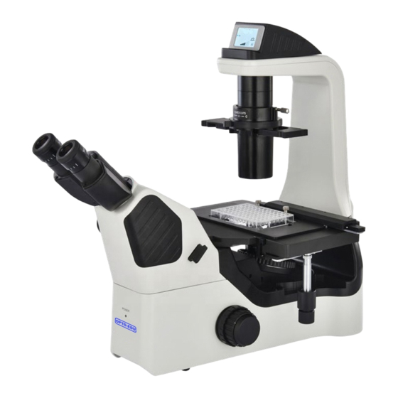
1.2 Components The microscope A14.1063 components ( following diagrams),A14.1064 add LCD based on A14.1063. Universal holder Eyepiece Condenser Viewing head Objective Mainframe Moving stage Stage Nosepiece A14.1063... - Page 13 The microscope A16.1064 components ( following diagrams),A16.1063 remove LCD based on A16.1064. Condenser Eyepiece Objective Viewing head Moving stage Universal holder Fluorescence Mainframe illumination Stage Filter Cube turret Nosepiece A16.1064...
-
Page 14: Chapter 2 Overview Of Agencies
Chapter 2 Overview of Agencies A16.1063 Condenser aperture adjustment knob Fine focus knob Contrast slider Coarse focus knob Upper lighting shading part(only FL) Condenser brightness adjuster Up/ down illumination switch( Transmitted Stage ) illumination for biological model Power switch Power indicator Nosepiece Camera mount... - Page 15 A16.1063 Emboss contrast slider Moving stage 10 Universal bracket/ holder Fluorescent baffle(only FL) Elastic adjustment knob 11 Condenser set screw Bracket horizontal movement knob Bracket vertical movement knob Fuse Outlet Built-in fluorescent light source part and fuse(only FL)...
-
Page 16: Condenser Aperture Adjustment Knob
A16.1064 Condenser aperture adjustment knob Fine focus knob Contrast slider Coarse focus knob adjuster ( only intelligent A14.1064 Universal bracket/ holder set screw series) Stage bracket/ holder Power indicator Fluorescence cube turret(only FL) Camera mount Power switch LCD(only A14.1064 series) Turntable cover(only FL)... -
Page 17: Upper Lighting Shading Part(Only Fl
A16.1064 Built-in fluorescent light source part Fluorescent baffle(only FL) and fuse(only FL) Universal bracket/ holder Nosepiece Emboss contrast slider Moving ruler/ Measuring head Elastic adjustment knob Upper lighting shading part(only FL) Bracket horizontal movement knob Condenser set screw Bracket vertical movement knob Outlet... -
Page 18: Chapter 3 Regulation And Operation
3.2 Turning the Illumination on switch ( for 3.2.1 Manual lighting Illumination A14.1063 series) switch Make sure the power indicator is on and press the light switch. 3.2.2 ECO switch (Optional functions) As shown in figure, the induction device can sense objects within 0.5m in front of... -
Page 19: Adjusting The Illumination Brightness
3.3 Adjusting the Illumination Brightness As shown in the direction of rotation, the light source is enhanced, whereas the light source weakened. 3.4 Specimen Placement and Stage Knob Adjustment Load the slide holder into a mechanical stage, cover glass slides downward slowly into the grooves of the slide plate. -
Page 20: Pallet
3.4.2 Holders There are a variety of holders to choose from. Model Terasaki micro plate Universal holder 54mm Petri dish holder/ Slide holder 60 mm Petri dish holder/ Slide holder 90 mm Petri dish holder 3.4.3 Auxiliary stage Connect the auxiliary stage to the left and Auxiliary stage right of the stage to expand the stage width. -
Page 21: Focusing On The Specimens
3.6 Focusing on the Specimens limit screw 3.6.1 Focus knob To adjust the focus, rotate the focus knobs on the right and left sides of the microscope to move the objective up and down. The figure to the right illustrates the relationship between the rotational direction of the focus knobs and the vertical notion of the objective. -
Page 22: Adjusting The Diascopic Illumination Aperture Diaphragm
3.7 Adjusting the Transmitted Illumination Aperture Diaphragm Insert a centering telescope in the eyepiece tube, adjust the focal length, and view the objective pupil plane (a bright circle) and the aperture diaphragm image. Adjust the aperture diaphragm so that the size of the Aperture diaphragm diaphragm image is 70-80% of the size of open/ close lever... -
Page 23: Operation The Phase Contrast Microscope
3.9 Operation the Phase Contrast Microscope Phase contrast microscopy requires phase contrast (PH) objectives and PH sliders. Annular diaphragm Hollow position Centering hold Centering hold (on the side) (on the side) If PH Slider is used, it is possible to center the annular diaphragm. Turn the centering screw of the PH slider to merge the annular diaphragm image with the phase ring image in the objective. -
Page 24: Operation The Emboss Contrast Microscope
3.10 Operation the Emboss Contrast Microscope To perform emboss contrast microscopy, a condenser-side emboss contrast slider and eyepiece-tube-side emboss contrast slider must be mounted on the microscope. 3.10.1 Condenser-side emboss contrast slider The condenser-side emboss contrast sector slider equipped with sector diaphragm diaphragm. -
Page 25: Operating The Episcopic Illumination
3.11 Operating the Episcopic Illumination Microscopy (for the NIB410-FL Only) ( 3.11.1 Episcopic illumination A14.1063-FL) As right figure shown, press the illumination switch switch between episcopic illumination LED and diascopic illumination fluorescent LED mode. Fluorescent illumination will turn weaker, when... -
Page 26: Fluorescence Filter Cube
position, seen from front microscope: If you select the bright-field position, the filter cube is removed from the optical path. The three bright-field positions have the same function. SIGN Rotate the turret so that the fluorescence positions indicated by the arrows on the left and right are the same (all points to “1”... -
Page 27: Operating The Lcd
3.12 Operating the LCD(for A14.1064 series) 3.12.1 The status of LCD Start & working mode Standby SLEEP Lock Time setting TIME 3.12.2 Operating the illumination switch Click brightness adjuster:becoming standby mode,it’s“SLEEP”in the screen。Click again,it becomes working mode。 Press brightness adjuster three seconds:setting time. First minute scale figures flash, then click the button, hour scale figures become flashing. -
Page 28: Chapter 4 Assembly
Chapter 4 Assembly 4.1 Installation diagram The order of installation of each component is shown in the following figure, and the digital indicate the installation step. Save the supplied hexagonal spanner. You need it when you change parts. CAUTION Before installation, make sure all the parts are free of dust and dirt. Do not scratch any part or surface of the glass. -
Page 29: Installation Steps
4.2 Installation Steps 4.2.1 Installing the Condenser Unscrew the captive screws on the condenser certain distance before aligning the tube with the dovetail groove of the condenser, then pushing lightly to the lowest position horizontally. and tighten the set screws. Set screw 4.2.2 Installing the Phase Contrast Slider With the sign facing up, push the phase... -
Page 30: Installing The Objective
4.2.4 Installing the Objective 1. Adjust the coarse focus knob until the converter drops to low limit. 2. Screw the objectives with the lowest magnification to the converter from the left or right and then push the nosepiece clockwise to install the other objectives in descending order of magnification. -
Page 31: Installing The Camera
4.2.7 Installing the Camera Remove dust cover from 1X relay 1X Relay lens lens. Screw the camera into the relay lens Dust as shown. cover In the process of installing the camera, pay attention to one hand always hold the camera to prevent fall and break. -
Page 32: Assembly Episcopic Illumination Microscopy
4.3 Assembly for Episcopic Illumination Microscopy 4.3.1 Attaching the Filter Cube Remove the cover from the filter cube mounting port. Turn the turret to a position where a Filter cube filter cube can be mounted easily. Check the address on the turret, and align the filter cube with the guide Cover groove before inserting. -
Page 33: Chapter 5 Maintenance And Storage
Chapter 5 Maintenance and Storage 5.1 Cleaning Clean or disinfect the lenses and other components according to the following instructions. Cleaning tools Blower Soft brush Soft cotton cloth, lens cleaning tissue, gauze, etc. Absolute alcohol (ethyl alcohol or methyl alcohol), medical alcohol ... -
Page 34: Cleaning Off Immersion Oil
Cleaning off Immersion Oil 5.1.3 (1) Wipe off using petroleum benzene. (2) Then, wipe off using absolute alcohol (ethyl alcohol or methyl alcohol) for a better finish. If petroleum benzene is unavailable If petroleum benzene is unavailable, use methyl alcohol. Note that methyl alcohol is less effective, and requires more wipes. -
Page 35: Chapter 6 Troubleshooting
Chapter 6 Troubleshooting 6.1 Optical System TROUBLE CAUSE SOLUTION The nosepiece is not in the Locate the nosepiece properly located position (objective and The edge of the where it clicks light path not coaxial) field of view is dark or the brightness is not uniform A lens (the objective, condenser, Clean it thoroughly... -
Page 36: Electrical Parts
6.2 Mechanical System TROUBLE CAUSE SOLUTION image cannot focus Specimen placed Turn it over; with the high-power reversely; Use standard cover glass with objective Cover slip is too thick thickness of 0.17mm The objective will Specimen placed Turn it over; touch the Specimen reversely;...
Need help?
Do you have a question about the A14.1063 and is the answer not in the manual?
Questions and answers