Table of Contents
Advertisement
Quick Links
Advertisement
Table of Contents
Troubleshooting

Subscribe to Our Youtube Channel
Related Manuals for CSI Wireless Vector Sensor


Summary of Contents for CSI Wireless Vector Sensor
- Page 1 Vector Sensor Reference Manual Part Number 875-0075-001 Date: March 2004...
- Page 2 Copyright Notice © Copyright 2004 CSI Wireless Inc. All rights reserved. No part of this manual may be stored in a retrieval system, transmitted, or reproduced by any means, including, but not limited to photocopy, photograph, digitizing, or otherwise, without the prior written permission from CSI Wireless Inc.
- Page 3 CSI Wireless, of any defective Products or components thereof. The end user shall notify CSI Wireless or a CSI Wireless approved service center immediately of any claimed defect. Repairs shall be made through a CSI Wireless approved service center only.
- Page 4 Obtaining Warranty Service In order to obtain warranty service, the end purchaser must bring the Product to a CSI Wireless approved dealer, along with the end purchaser’s proof of purchase. For any questions regarding warranty service or to obtain information regarding the location of any of CSI Wireless’s dealers, contact CSI Wireless at the following address.
-
Page 5: Table Of Contents
World Wide Web Site ....................xvi Document Conventions....................xvi Notes, Cautions, and Warnings..................xvi Quick Start........................17 Receiving Your Shipment................... 17 Unpacking Your Vector Sensor System............17 Cable Connections....................18 Understanding the Vector Sensor ..............18 1.4.1 Moving Base Station RTK..............19 1.4.2 Supplemental Sensors - Reduced Search Time........ - Page 6 Connecting the CDA-RTK and MBL-3 Antennas ......40 2.7.5 Powering the Vector Sensor..............40 2.7.6 Turning the Vector Sensor On............41 2.7.7 Connecting the Vector Sensor To External Devices...... 41 LED Indicators...................... 43 Overview........................45 GPS......................... 45 3.1.1 Satellite Tracking..................45 3.1.2...
- Page 7 GPS Firmware..................52 3.6.3 GPS Applications................... 52 3.6.4 Beacon Firmware ................... 53 Operation........................54 Powering the Vector Sensor................54 Communicating with the Vector Sensor ............54 4.2.1 NMEA 0183 Interface................54 4.2.2 Binary Interface..................55 4.2.3 RTCM SC-104 Protocol ............... 55 Configuring the Vector Sensor................
- Page 8 $GPMSK Beacon Tune Command............. 88 6.7.2 $PCSI,1 Beacon Status Command............88 GPS Heading Commands................... 89 6.8.1 $JATT,TILTAID..................90 6.8.2 $JATT,TILTCAL..................91 6.8.3 $JATT,MAGAID..................91 6.8.4 $JATT,MAGCAL..................91 6.8.5 $JATT,MAGCLR ..................92 6.8.6 $JATT,GYROAID.................. 93 6.8.7 $JATT,LEVEL..................93 Vector Sensor Reference Manual viii...
- Page 9 Bin 97.....................107 7.1.9 Bin 98.....................108 7.1.10 Bin 99.....................109 Frequently Asked Questions.................111 Heading........................111 General........................111 Support and Repairs ..................112 Troubleshooting....................112 Power, Communication, and Configuration ..........113 GPS Reception and Performance..............114 SBAS Reception and Performance..............114 Beacon Reception and Performance..............115 External Corrections..................116 Vector Sensor Reference Manual...
- Page 10 8.10 Installation ......................116 Troubleshooting.......................117 Appendix A - Specifications....................119 Appendix B - Interface......................122 Appendix C - Introduction to GPS and SBAS ..............125 Appendix D - Resources......................142 Index ............................144 Vector Sensor Reference Manual...
-
Page 11: List Of Figures
Figure 2-2 DB9 Socket Numbering..................42 Figure 2-3 Port A Interface....................42 Figure 2-4 Port B Interface..................... 43 Figure 2-5 Vector Sensor Evaluation Front Panel ............. 44 Figure 6-1 PocketMAX Screen Capture................61 Figure B-1 GPS Data Interface....................122 Figure B-2 RTCM Data Output Interface................123 Figure C-1 WAAS Coverage....................135... - Page 12 Table 6-16 SBX Beacon Commands..................87 Table 6-17 GPS Heading Commands.................. 90 Table 7-1 Binary Message Structure ..................102 Table 7-2 Bin 1 Message......................103 Table 7-3 Bin 2 Message......................103 Table 7-4 Bin 80 Message....................104 Table 7-5 Bin 93 Message....................105 Vector Sensor Reference Manual...
- Page 13 Table 7-8 Bin 96 Message....................107 Table 7-9 Bin 97 Message....................108 Table 7-10 Bin 98 Message....................108 Table 7-11 Bin 99 Message....................109 Table 9-1 Troubleshooting....................117 Table A-1 Specifications.......................119 Table A-2 Vector Antenna Array Specifications.............120 Table A-3 MBL-3 Specifications..................120 Vector Sensor Reference Manual xiii...
-
Page 14: Preface
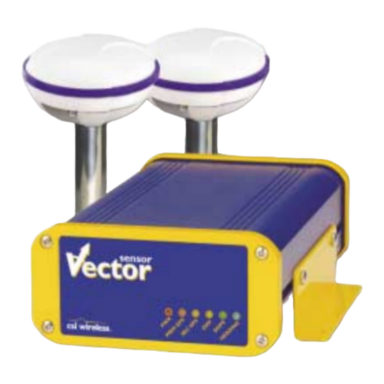
Vector Sensor, a Vector Antenna Array, an MBL-3 beacon antenna, and required cables. The Vector Sensor has been designed primarily for the Marine market, however it is also suitable for other markets, such as Machine Control and Agricultural Guidance. This reference manual has... -
Page 15: Organization
Introduction - provides an introduction to GPS and DGPS technology, and the Vector Sensor system. Chapter 2: Installation - describes how to install the Vector Sensor, Vector Antenna Array, MBL-3, and provides a foundation for interfacing it with an external navigation system or similar device. Chapter 3: Overview - provides details on the fundamental operating modes of the Vector Sensor system and its associated default parameters. -
Page 16: World Wide Web Site
In the event that your equipment requires service, we recommend that you contact your dealer directly. However, if this is not possible, you must contact CSI Wireless Customer Service to obtain a Return Merchandise Authorization (RMA) number before returning any product to CSI Wireless. -
Page 17: Quick Start
The Vector Sensor is a highly functional system, and as such, it will take care to successfully install and configure. Although this chapter is titled Quick Start, the volume of information presented may be initially overwhelming, however, the default configuration of the Vector Sensor provides a functional heading foundation that satisfies many requirements little additional configuration. -
Page 18: Cable Connections
GPS receiver be given the correct antenna to use, otherwise the heading solution will be off by 180° (which could be corrected in the software configuration of the Vector Sensor). Heading is always computed from the antenna connected to the primary GPS receiver to the antenna connected to the secondary GPS receiver. -
Page 19: Moving Base Station Rtk
1.4.1 Moving Base Station RTK The Vector Sensor’s internal GPS engines use both the L1 GPS C/A code and carrier phase data to compute the location of the secondary GPS antenna in relation to the primary GPS antenna with a very high sub-centimeter level of precision. -
Page 20: Installation Overview
For example, if the Antenna Array points to the bow of the vessel (a normal configuration), the Vector Sensor will face the stern of the vessel so that the front panel is visible to the crew. This is a requirement if any or a combination of the tilt sensor, magnetic sensor, and gyro are used. -
Page 21: Mounting Configurations And Offset Settings
• Configure for your desired mode of differential operation (either SBAS, beacon, or external corrections) • If you are using the second dimension of attitude provided by the Vector Sensor (either roll or pitch, depending on the Antenna Array orientation), configure the Vector Sensor appropriately (the default is pitch) •... -
Page 22: Nmea 0183 Message Interface
The Vector sensor’s internal tilt sensor (accelerometer) is enabled by default and constrains the RTK heading solution to reduce startup and reacquisition times. Since this sensor resides inside the Vector Sensor, the receiver enclosure must be installed in a horizontal plane, as must the Antenna Array, To turn the tilt-aiding feature off, use the following command. -
Page 23: Magnetometer Calibration
360° approximately 3 to 10 times. Calibration should be performed in a clear environment without any potential satellite blockages to minimize any possible errors during the process. The command to initialize the magnetic calibration process follows. Vector Sensor Reference Manual... -
Page 24: Gyro Aiding
1.8.5 Gyro Aiding The Vector Sensor’s internal gyro is shipped on by default, and it offers two benefits. It will shorten reacquisition times when a GPS heading is lost, due to obstruction of satellite signals, by reducing the search volume required for solution of the RTK. -
Page 25: Time Constants
Vector’s power is cycled. 1.8.6 Time Constants The Vector Sensor incorporates user-configurable time constants that can provide a degree of smoothing to the heading, course over ground, and speed measurements. The following sections describe how to configure their values. - Page 26 The resulting heading would have reduced ‘noise’, resulting in consistent values with time. However, artificially increasing this value such that it does not agree with a more dynamic vessel Vector Sensor Reference Manual...
- Page 27 (in seconds) = maximum rate of the rate of turn (in °/s ) / 10 You may query the Vector Sensor for the current heading rate time constant by issuing the same command without an argument. $JATT,HRTAU<CR><LF>...
-
Page 28: Level Operation
$JATT,LEVEL<CR><LF> 1.8.8 Heading Compensation You may adjust the heading output from the Vector Sensor in order to calibrate the true heading of the Antenna Array to reflect the true heading of the vessel using the following command. Vector Sensor Reference Manual... -
Page 29: Configuring For Pitch Or Roll
$JATT,HBIAS,x<CR><LF> Where x is a bias that will be added to the Vector Sensor’s heading, in degrees. The acceptable range for the heading bias is -180.0° to 180.0°. The default value of this feature is 0.0°. To determine what the current heading compensation angle is, send the following message to the Vector Sensor. -
Page 30: Pitch / Roll Compensation
/ roll reading from the Vector Sensor. $JATT,PBIAS,x<CR><LF> Where x is a bias that will be added to the Vector Sensor’s pitch / roll measure, in degrees. The acceptable range for the heading bias is -15.0° to 15.0°. The default value of this feature is 0.0°. -
Page 31: Forcing A New Rtk Search
1.8.12 Forcing a New RTK Search You may force the Vector Sensor to reject the current RTK heading solution, and have it begin a new search with the following command. $JATT,SEARCH<CR><LF> 1.8.13 Antenna Separation You may wish to increase the separation between antenna phase centers in order to achieve higher heading and pitch / roll performance. -
Page 32: Summary Command
Chapter 6 summarizes this output in detail. 1.8.15 HELP command The Vector Sensor supports a command that you can use to get a short list of the supported commands if you find yourself in the field without documentation. This commands has the following format. -
Page 33: Hehdt Message
This message can be output only at 1 Hz is turned on using the following command. $JASC,INTLT,1<CR><LF> To turn this message off, use the following command. $JASC,INTLT,0<CR><LF> The details of this command and the $PSAT,INTLT message are described in Chapter 6. Vector Sensor Reference Manual... -
Page 34: Proprietary $Psat,Hpr Message
$JASC,HPR,rate<CR><LF> Where ‘rate’ may be any of the following values expressed in Hz: 0, 1, 5, 10, or 0.2. The details of this command and the $PSAT,HPR data message are described in Chapter 6. Vector Sensor Reference Manual... -
Page 35: Installation
Vector requires connection to primary and secondary GPS antennas. The RF connection to the MBL-3 beacon antenna is optional, however required if the beacon DGPS corrections are required and services are available in the region of Vector Sensor usage. SBAS reception is accomplished through the primary CDA-RTK antenna. -
Page 36: Vector Antenna Array Placement
This will ensure that tracking performance of the Vector Sensor is not compromised, giving you the best performance possible. • Make sure that there is sufficient length of the extension cable available to install the Vector Sensor in the desired location •... -
Page 37: Environmental Considerations
95% relative non-condensing humidity. 2.5 Power Considerations The Vector Sensor is powered with an input voltage of between 8 and 40 VDC. For best performance, the supplied power should be continuous and clean. Table 2-1 details the power specifications of the Vector Sensor. -
Page 38: Magnetic Mounting (Optional Accessory)
Note - The maximum antenna separation that we recommend is 2.0 m. Any increase beyond this limit is at your risk or the Vector Sensor solving for the wrong RTK position of the secondary GPS antenna, resulting in an incorrect heading 2.7.1 Magnetic Mounting (Optional Accessory) -
Page 39: Routing And Securing The Antenna Cable
(49 ft) in length) for proper operation. The GPS engines inside the Vector Sensor require a minimum input gain of 10 dB (and maximum of 40 dB before saturation will occur). The CDA-RTK antennas offer 28 dB of gain, so the loss budget to accommodate for cable losses is 18 dB. -
Page 40: Connecting The Cda-Rtk And Mbl-3 Antennas
TNC-male-to-TNC-male antenna cables. To connect the CDA-2MAX Antenna to the DGPS MAX: • Connect the CDA-RTK antenna labelled Primary RF to the primary GPS RF port on the Vector Sensor • Connect the CDA-RTK antenna labelled Secondary RF to the secondary GPS RF port on the Vector Sensor •... -
Page 41: Turning The Vector Sensor On
2.7.6 Turning the Vector Sensor On When connected to a suitable power source, the Vector Sensor may be turned on and off using the ON/OFF switch located on the rear panel. To turn the Vector Sensor on: Ensure that the red wire of the supplied power cable is connected to DC positive (+). -
Page 42: Figure 2-2 Db9 Socket Numbering
The associated numbering for the plug connector (male) is a mirror reflection of scheme showed in this figure. Figure 2-2 DB9 Socket Numbering Figure 2-3 and 2-4 illustrate the standard interface for the Vector Sensor when interfaced to an external device with either the Port A or Port B serial ports. External Device... -
Page 43: Led Indicators
Chapter 6 describes the baud rate change command. 2.8 LED Indicators The Vector Sensor features diagnostic LEDs located on the front panel that provide a quick indication of module status as described in the following table. Table 2-5 LED Indicator Definitions... -
Page 44: Figure 2-5 Vector Sensor Evaluation Front Panel
The following figure displays the front panel layout of the Vector Sensor, including the location and labeling of each LED. Figure 2-5 Vector Sensor Evaluation Front Panel Vector Sensor Reference Manual... -
Page 45: Overview
For your convenience, both the GPS and SBAS operation of the Vector Sensor features automatic operational algorithms. However, you must program the Vector Sensor for which differential service to use. The Vector Sensor does not automatically choose one service over the other. By default, the Vector Sensor operates with SBAS corrections. -
Page 46: Update Rates
SBAS services and intermittent beacon reception for up to 30 to 40 minutes, depending on the amount of tolerable performance drift. After 30 minutes, our testing has shown that the Vector Sensor This feature operates by default and is adjusted by setting the maximum differential age as needed. -
Page 47: Beacon Operation
GPS ionospheric model and the ionospheric SBAS map. To minimize the impact of this issue on your use of the Vector Sensor, we may wish to wait up to five minutes before using the Vector Sensor or issue the $JQUERY,GUIDE<CR><LF>... - Page 48 The beacon receiver’s two channels cooperatively examine the frequencies with the highest SS measurements, above the computed noise floor, to determine the station providing the strongest RTCM signal. The receiver's primary channel locks to the first identified DGPS broadcast, while Vector Sensor Reference Manual...
-
Page 49: Receiver Performance
If no signal is available, the Vector Sensor will initiate a fresh Global Search, continuing this cycle until it finds a valid station. 3.3.1.3 ABS Background Beacon Search During the Background Search, the second beacon channel examines all frequencies at both 100 and 200 bps MSK bit rates to identify beacons possessing superior signal quality. -
Page 50: Coast™ Technology
This means that the Vector Sensor GPS is more tolerant than competing products to loss of SBAS or externally input RTCM SC-104 corrections. - Page 51 Vector Sensor Reference Manual...
-
Page 52: Vector Sensor Architecture
There are two types of firmware within the Vector Sensor. One type of firmware drivers the on- board digital signal processors (DSP) and another the ARM processors. Each of these types of firmware may be upgraded in the field through Port A for the primary GPS receiver as new revisions become available. -
Page 53: Beacon Firmware
3.6.4 Beacon Firmware The Vector Sensor’s internal beacon module incorporates its own version of firmware that controls its operation. This firmware can be updated independent of the Vector GPS firmware if needed through Port A or B. -
Page 54: Operation
8 to 40 VDC power source. You will need to press the ON/OFF switch on the back panel of the Vector Sensor in order to turn the receiver system on or off once connected to a suitable power source. Once powered, the Vector Sensor will proceed through an internal start-up sequence, however it will be ready to communicate within a few seconds. -
Page 55: Binary Interface
The Vector Sensor supports a variety standard and proprietary NMEA messages. These messages are used to configure the Vector Sensor and also contain the required information from the system. You may configure a selection of NMEA 0183 data messages on one port at various update rates (each message has a maximum update rate) and a different selection of NMEA 0183 messages with different rates on the other port. -
Page 56: Configuring The Vector Sensor
The scatter or the receiver is likely to remain close to constant. The RTCM SC-104 data output by the Vector Sensor is converted from the RTCM SC-159 data broadcast by SBAS. Appendix D - Resources contains the contact information should you wish to purchase a copy of the RTCM SC-104 specification. -
Page 57: This Port And The Other Port
‘Other’ port. For example, if you are communicating with the Vector Sensor Port B, and wish to turn the GPGGA message on at an update rate of 5 Hz on Port A, the following command would be used. -
Page 58: Pocketmax Utility
PocketMAX is a freely available Windows PocketPC utility designed for use with CSI Wireless SLX and SX-1 based products, including the Vector Sensor. As this utility was not designed specifically for any one product alone, it supports features not offered by every product, such as tracking of the OmniSTAR differential service and display of our Vector product’s true heading, however, the... - Page 59 Vector Sensor Reference Manual...
-
Page 60: Nmea 0183 Messages
Null, or empty fields occur when no information is available for that field. 6.2 PocketMAX CSI Wireless offers a configuration program designed for Windows PocketPC software that runs on PocketPC 2000, 2002 and 2003 platforms. It can be used to configure and monitor your differential source, GPS messages and it also records various types of data. -
Page 61: General Commands
Figure 6-1 PocketMAX Screen Capture 6.3 General Commands This section presents various commands relating to the general operation and configuration of the Vector Sensor. The following table provides a brief description of the general commands supported by the Vector Sensor. Vector Sensor Reference Manual... -
Page 62: Jasc,D1
SBAS signal more quickly upon start-up. This is not normally needed. $JQUERY,GUIDE This command is used to poll the Vector Sensor for its opinion on whether or not it is providing suitable accuracy after the both SBAS and GPS have been... -
Page 63: Jair
For example, if RTCM is input on Port B, this data will correct the position and also be output through Port A. The Vector Sensor acts as a pass-through for the RTCM data. Either port may be configured to accept RTCM data input and this command then allows the opposite port to output the RTCM data. -
Page 64: Jalt
$> 6.3.4 $JALT This command turns altitude aiding on or off for the Vector Sensor module. When set to on, altitude aiding uses a fixed altitude instead of using one satellite’s observations to calculate the altitude. The advantage of this feature, when operating in an application where a fixed altitude is acceptable, is that the extra satellite’s observations can be used to betterment of the latitude,... -
Page 65: Jlimit
6.3.6 $JAPP This command allows you to request the Vector Sensor for the currently installed applications and to choose which application to use. Both internal GPS engines each have two copies of their firmware in both application slots. This ensures that the application is not accidentally changed such that the receiver fails to function correctly. -
Page 66: Jbaud
6.3.8 $JCONN This command is used to create a virtual circuit between the A and B port, if needed. This allows you to communicate through the Vector Sensor from Port A or B to the opposite port. Vector Sensor Reference Manual... -
Page 67: Jdiff
‘X’ in this command to return the current port to normal 6.3.9 $JDIFF This command is used to change the differential mode of the Vector Sensor receiver. The default differential mode is SBAS (WAAS). The structure of this command follows. -
Page 68: Jpos
6.3.12 $JQUERY,GUIDE This command is used to poll the Vector Sensor for its opinion on whether or not it is providing suitable performance after the both SBAS and GPS have been acquired (up to 5 min). This feature takes into consider the download status of the SBAS ionospheric map and also the carrier phase smoothing of the GPS. -
Page 69: Jreset
6.3.13 $JRESET This command is used to reset the Vector Sensor GPS engines to their default operating parameters. This message has the following format. $JRESET<CR><LF> 6.3.14 $JSAVE Sending this command is required after making changes to the operating mode of the Vector Sensor in order to ensure the changes are present for the subsequent power cycle. - Page 70 The subset field may be either CONF or GP. When CONF is specified for ‘subset’, the following response is provided. $>JSHOW,CONF,N,0.0,10.0,5,A,60W This response is summarize d in the following table. Message Description Component Vector Sensor Reference Manual...
- Page 71 This response will provide the >$JSHOW,GP message header, followed by each message currently being output through the current port and also the update rate for that message. 6.3.16 $JT This command displays the type of receiver engine within the Vector Sensor and has the following format. $JT<CR><LF>...
-
Page 72: Jbin
Binary message containing satellite and almanac information. Bin99 5, 1, 0, or .2 Binary message containing GPS diagnostic information. The Vector Sensor will reply with the following response. $> 6.4 GPS Commands This section describes the selection of commands specific to the configuration and operation of the Vector Sensor. -
Page 73: Jasc
Internal tilt sensor measurement 10, 5, 1, 0, or .2 Proprietary message containing heading and roll or pitch When the ‘,OTHER’ data field is specified (without the square brackets), this command will enact a change on the other port. Vector Sensor Reference Manual... -
Page 74: Jage,Age
This command allows you to choose the maximum allowable age for correction data. The default setting for the Vector Sensor is 1800 seconds, however, you may change this value as you feel appropriate. This setting inherently defines how long a receiver should coast using the COAST feature. -
Page 75: J4String
This message has the following format. $JMASK,e<CR><LF> Where the elevation mask cutoff angle, ‘e’, may be a value from 0 to 60 degrees. The Vector Sensor will reply with the following response. $> 6.4.5 $J4STRING This command allows the GPGGA, GPVTG, GPGSA, and GPZDA messages to all be output with the issue of a single command. -
Page 76: Sbas Commands
‘$> Save Complete’ response. 6.5.1 $JWAASPRN This command allows you to both poll the Vector Sensor’s internal SBAS demodulator SBAS PRN’s in memory, and change them, if desired. To poll the receiver for the current SBAS PRN’s, send the following message. -
Page 77: Jgeo
This message is used to display information related to the current frequency of SBAS, and its location in relation to the Vector Sensor’s antenna. Knowing the location of the SBAS satellites can be very useful when troubleshooting a reception problem, as in some geographic regions, these satellites may appear quite low on the horizon. -
Page 78: Jasc,D1
SBAS through either Port A or B. The correction data output is RTCM SC-104 even though SBAS uses a different over-the-air protocol (RTCA SC-159). To have the Vector Sensor unit output RTCM corrections, send the following command to the smart antenna. -
Page 79: Data Messages
When the ‘,OTHER’ data field is specified (without the square brackets), this command will turn RTCM data on or off on the other port. The Vector Sensor will reply with the following response. $> 6.6 Data Messages The following subsections describe the NMEA data messages listed in Table 6-5 in detail. -
Page 80: Gga Data Message
= E or s = W, for East or West longitude hhmmss.ss UTC time in hours, minutes, and seconds of GPS position Status, s = A = valid, s = V = invalid Checksum <CR><LF> Carriage return and line feed Vector Sensor Reference Manual... -
Page 81: Gsa Data Message
Standard deviation of semi-minor axis of error ellipse (meters) Orientation of semi-major axis of error ellipse (degrees) Standard deviation of latitude error (meteers) Standard deviation of longitude error (meters) Standard deviation of altitude error (meters) Checksum <CR><LF> Carriage return and line feed Vector Sensor Reference Manual... -
Page 82: Gsv Data Message
Track made good, referenced to true north ddmmyy UTC date of position fix in day, month, year Magnetic Variation in degrees Variation sense v = E = East, v = W = West Checksum <CR><LF> Carriage return and line feed Vector Sensor Reference Manual... -
Page 83: Rre Data Message
Speed over ground, 000 to 999 knots Speed over ground units, u = N = Nautical mile/h ggg.gg Speed over ground, 000 to 999 km/h Speed over ground units, u = K = kilometer/h Checksum <CR><LF> Carriage return and line feed Vector Sensor Reference Manual... -
Page 84: Zda Data Message
Checksum <CR><LF> Carriage return and line feed The following table describes the DSP status. The DSP status should be 17, 1B, or 1F when SBAS tracking has been achieved. Vector Sensor Reference Manual... - Page 85 The number of satellites that are tracked, have an ephemeris, which is healthy, and are above the elevation mask The number of satellites above the elevation mask The number of satellites with differential The number of satellites with no differential Vector Sensor Reference Manual...
-
Page 86: Pcsi,1 Beacon Status Message
6.6.11 $PCSI,1 Beacon Status Message This message contains a variety of information relating to the status of a CSI Wireless SBX engine inside the Vector Sensor. The $PCSI,1 output message from the SBX beacon module is intelligently routed through the Vector Sensor to the port from which the $PCSI,1 message was requested (either Port A or B). -
Page 87: Hdt Data Message
Port A or Port B of the Vector Sensor. Table 6-16 SBX Beacon Commands Message Description $GPMSK Command to turn on diagnostic information. $PCSI,1 This command is used to get beacon status information from the SBX beacon engine inside the Vector Sensor. Vector Sensor Reference Manual... -
Page 88: Gpmsk Beacon Tune Command
6.7.2 $PCSI,1 Beacon Status Command This command is used to obtain $PCSI,CS0 beacon status data from the SBX beacon engine inside the Vector Sensor. When this command is sent through either Port A or B, it will automatically be Vector Sensor Reference Manual... -
Page 89: Gps Heading Commands
Where x is the desired output period in seconds. The ‘S’ field must be present and be capitalized. 6.8 GPS Heading Commands This section details the various settings that relate to the GPS heading aspect of the Vector Sensor system. -
Page 90: Jatt,Tiltaid
The Vector sensor’s internal tilt sensor (accelerometer) is enabled by default and constrains the RTK heading solution to reduce startup and reacquisition times. Since this sensor resides inside the Vector Sensor, the receiver enclosure must be installed in a horizontal plane, as must the Antenna Array, To turn the tilt-aiding feature off, use the following command. -
Page 91: Jatt,Tiltcal
6.8.2 $JATT,TILTCAL The tilt sensor of the Vector Sensor can be calibrated in the field, however the Vector Sensor enclosure must be horizontal when performing the calibration. To calibrate the Vector Sensor’s internal tilt sensor, issue the following command. $JATT,TILTCAL<CR><LF>... -
Page 92: Jatt,Magclr
If the receiver responds with a negative, continue rotating and re-issue the MAGCAL command periodically until the calibration has been accepted. If the Vector Sensor system is reinstalled in a different location, even on the same vessel, you will need to clear the calibration table with the $JATT,MAGCLR command and complete the new calibration. -
Page 93: Jatt,Gyroaid
Vector’s power is cycled. 6.8.7 $JATT,LEVEL This command is used to invoke the level operation mode of the Vector Sensor. If your application will not involve the system tilting more than ±10° maximum, then you may choose to use this mode of operation. -
Page 94: Jatt,Csep
To determine the current status of this message, issue the following command. $JATT,LEVEL<CR><LF> 6.8.8 $JATT,CSEP This command polls the Vector Sensor for the current separation between antennas, as solved for by the attitude algorithms. It has the following format. $JATT,CSEP<CR><LF>... -
Page 95: Jatt,Ptau
(in seconds) = maximum rate of turn (in °/s) / 10 You may query the Vector Sensor for the current heading time constant by issuing the same command without an argument. -
Page 96: Jatt,Cogtau
(in seconds) = maximum rate of the rate of turn (in °/s ) / 10 You may query the Vector Sensor for the current heading rate time constant by issuing the same command without an argument. $JATT,HRTAU<CR><LF>... -
Page 97: Jatt,Spdtau
Antenna Array to reflect the true heading of the vessel using the following command. $JATT,HBIAS,x<CR><LF> Where x is a bias that will be added to the Vector Sensor’s heading, in degrees. The acceptable range for the heading bias is -180.0° to 180.0°. The default value of this feature is 0.0°. -
Page 98: Jatt,Pbias
/ roll reading from the Vector Sensor. $JATT,PBIAS,x<CR><LF> Where x is a bias that will be added to the Vector Sensor’s pitch / roll measure, in degrees. The acceptable range for the heading bias is -15.0° to 15.0°. The default value of this feature is 0.0°. -
Page 99: Jatt,Search
$JATT,SEARCH<CR><LF> If the Vector Sensor has a lock before this command is sent, you will see the heading LED go out once the command has been sent. The heading LED will turn back on when a new heading solution has been achieved. - Page 100 GN = hex ( 02 + 0 ) = hex ( 02 ) = 2 RMTL = hex ( 08 + 04) = hex (12) = C ‘GN-RMTL’ = 2C The following tables summarize the possible feature configurations for the first GN character and the second RMTL character. Vector Sensor Reference Manual...
-
Page 101: Jatt,Help
Tilt Aiding Level 6.8.22 $JATT,HELP The Vector Sensor supports a command that you can use to get a short list of the supported commands if you find yourself in the field without documentation. This commands has the following format. $JATT,HELP<CR><LF>... -
Page 102: Binary Data
7.1 Binary Message Structure The Binary messages supported by the Vector Sensor are in an Intel Little Endian format for direct read in a PC environment. You can find more information on this format at the following Web site. -
Page 103: Bin 80
MaskSatsTracked A mask of satellites tracked by Unsigned Individual bits the GPS. Bit 0 corresponds to long represent the GPS satellite with PRN 1. satellites MaskSatsUsed A mask of satellites used in the Unsigned Individual bits Vector Sensor Reference Manual... -
Page 104: Bin 94
Not used at this time Unsigned short Future use MsgSecOfWeek Seconds of week for message Unsigned long WaasMsg[8] 250 bit WAAS message (RTCA Unsigned long 4 x 8 = DO-229). 8 unsigned longs with most significant bit received first Vector Sensor Reference Manual... -
Page 105: Bin 95
Long XGDotDot Bit 0 = 0.0000125 m/s Long YGDotDot Bit 0 = 0.0000125 m/s Long ZGDotDot Bit 0 = 0.0000625 m/s Long Bit 0 = 2**-31 s Unsigned short Gf0Dot Bit0 = 2**-40 s/s Unsigned short Vector Sensor Reference Manual... -
Page 106: Bin 96
SF1words[10 Unparsed SF 1 message Unsigned long 4 x 10 = 40 SF2words[10 Unparsed SF 2 message Unsigned long 4 x 10 = 40 SF3words[10 Unparsed SF 3 message Unsigned long 4 x 10 = 40 Vector Sensor Reference Manual... -
Page 107: Bin 98
7.1.8 Bin 97 This message has a BlockID of 97 and is 28 bytes excluding the header and epilogue. This message contains statistics for processor utilization. The following table describes the details of this message in order. Vector Sensor Reference Manual... -
Page 108: Table 7-9 Bin 97 Message
(assuming a stationary satellite). CountUpdat Number of times the almanac has Byte Positive changed for this satellite since the receiver was turned on Svindex Channel number (groups of 8) Byte 0 to 7 Vector Sensor Reference Manual... -
Page 109: Bin 99
12 receiver channels ClockErrAtL1 The clock error of the Short -32768 to 32768 GPS clock oscillator at L1 frequency in Hz Spare Not used at this time Unsigned Future use short Vector Sensor Reference Manual... - Page 110 GPS solution for this chanel VelResid 10 times the velocity residual from Short the GPS solution for this channel DoppHZ Expected Doppler for this channel Short in Hz NCOHz Carrier track offset for this channel Short in Hz Vector Sensor Reference Manual...
-
Page 111: Frequently Asked Questions
A - It partially depends on regulations regarding on the size of your vessel and if you’re going to use the Vector Sensor for positioning in addition to heading. You may be required to use beacon corrections when positioning if you plan to use the position output from the Vector Sensor. If this is not the case, you will likely find that the beacon and SBAS are able to provide good levels of performance. -
Page 112: Support And Repairs
8.4 Troubleshooting Q - What do I do initially if I have a problem with the operation of the Vector Sensor? A - Try to isolate the source of the problem. Problems are likely to fall within one of the following categories. -
Page 113: Power, Communication, And Configuration
19,200, or vice versa. Q - Am I able to have the Vector Sensor output different NMEA messages through the two ports? A - Yes, you may have different NMEA messages turns on for the two serial ports. Further, these NMEA messages may also be at different update rates. -
Page 114: Gps Reception And Performance
$GPGGA data message. Also, the front panel LEDs provide status indication. Q - Do I have to be careful when using the Vector Sensor to ensure that it tracks properly? A - For best performance, you have to be careful such that the hemisphere above the Vector Antenna Array is unobstructed for satellite tracking. -
Page 115: Beacon Reception And Performance
Q - How do I know if the Vector Sensor is offering a differentially corrected position? A - The DGPS LED on the front panel of the Vector Sensor tells you if a differentially correction position is currently being output. Additionally, the Vector Sensor outputs the GGA message as the main positioning data message by default. -
Page 116: External Corrections
A - This could be due to a number of issues: • Make sure that the corrections are of an RTCM SC-104 protocol. • Check to see that the baud rates of the port used by the Vector Sensor matches that of the external correction source •... -
Page 117: Troubleshooting
9. Troubleshooting Use the following checklist to troubleshoot anomalous Vector Sensor receiver operation. Table 9- 1 provides a problem symptom, followed by a list of possible solutions. Table 9-1 Troubleshooting Symptom Possible Solution • Receiver fails to power Verify polarity of power leads •... - Page 118 RTCM input port and grounds must be connected - Refer to Appendix B) • Non-differential GPS output Verify Vector Sensor SBAS and beacon lock status (or external source is locked) • Confirm baud rates match an external source correctly •...
-
Page 119: Appendix A - Specifications
Appendix A - Specifications This appendix provides the operational, mechanical, electrical, physical, and environmental specifications of the Vector Sensor system. Table A-1 Vector Sensor Specifications Internal GPS Engine Operational Specifications Item Specification Frequency 1.575 GHz Channels 12 parallel tracking Horizontal Accuracy <... -
Page 120: Table A-2 Vector Antenna Array Specifications
25 to 35 mA Mechanical Characteristics Item Specification Enclosure PVC plastic Mounting Thread 1-14-UNS-2B Antenna Connector TNC socket Length 128 mm (5.06”) Width 128 mm (5.06”) Height 84 mm (3.33”) Weight 450 g (1.0 lb) - no cable, un-mounted Vector Sensor Reference Manual... - Page 121 Environmental Specifications Item Specification Storage Temperature -40°C to 80°C Operating Temperature -30°C to 70°C Humidity 100% Non -condensing Vector Sensor Reference Manual...
-
Page 122: Appendix B - Interface
Vector Sensor system. Otherwise, this connection is optional. • Connect Pin-5 - signal ground of either Vector Sensor port to the signal return or of the external device. This configuration is also used for the output of RTCM data and binary messages from either serial port. -
Page 123: Figure B-2 Rtcm Data Output Interface
External Correction Input In this operating mode, an external correction device inputs RTCM correction data through either Vector Sensor Port A or B. In order to accomplish this, the Vector Sensor must be commanded to use external corrections using the $JDIFF command. - Page 124 • Communicate with the Vector Sensor on Port A. Ensure that the baud rate of Port B and the external correction source match by issuing the appropriate $JBAUD command. • Issue a $JDIFF,OTHER<CR><LF> command through Port A. You may configure the Vector Sensor to accept corrections on Port A by using the same procedure but by switching the Port A and B references.
-
Page 125: Appendix C - Introduction To Gps And Sbas
C/A code. The DoD provides the SPS free of charge, worldwide, to all civilian users. In order to maintain a strategic advantage, the US DoD used to artificially degrade the performance of the SPS so that the positioning accuracy was limited to 100 meters 95% of the time. This Vector Sensor Reference Manual... - Page 126 GPS raw measurement data. The Vector Sensor can be configured to output raw measurement data at rates of up to 5 Hz in a proprietary format. This data can be converted to an industry standard RINEX format if needed.
- Page 127 Space Based Augmentation Systems (SBAS) such as the European Geostationary Navigation Overlay System (EGNOS) and the Japanese MT-SAT Satellite-based Augmentation System (MSAS) use this data format. The Vector Sensor system is compatible with each of these differential services.
- Page 128 A floating integer solution can offer a designer more flexibility, but it does not provide as much accuracy as a fixed integer ambiguity solution. The Vector Sensor uses a fixed integer ambiguity solution for computing real-time heading and is able to solve the...
- Page 129 (the sum of the antennas and the bracket is referred to as the Vector Antenna Array). In the case of the Vector Sensor being used on a marine vessel for heading, when differencing the measurements, only the relative motion of the rover antenna with respect to the base will remain.
- Page 130 Compared to using a DGPS beacon, the effect of geographic proximity to a single reference station is minimized resulting in more consistent system performance throughout all locations within the network. Vector Sensor Reference Manual...
- Page 131 Higher accuracy GPS receivers are able to achieve sub-1 meter horizontal accuracy 95% of the time using real-time DGPS transmissions. The Vector Sensor system falls in to this latter category. Vector Sensor Reference Manual...
- Page 132 • The Space Segment includes geostationary satellites (For example, WAAS and EGNOS use Inmarsat-III transponders) • The user segment consists of the user equipment, such as the Vector Sensor A SBAS uses a state-based approach in their software architecture. This means that a separate correction is made available for each error source rather than the sum effect of errors on the user equipment’s range measurements.
- Page 133 60 km. There must be sufficient ionospheric map coverage beyond your location in order to have ionospheric correctors for all satellites. To enhance the information provided by SBAS, the Vector Sensor system extrapolates the ionospheric information beyond the broadcast information. This increases the usable geography for WAAS and is discussed in Section 1.5.5.
- Page 134 COAST technology helps to maintain system performance during times of differential outage. When using SBAS correction data, the Vector Sensor is able to provide you with the azimuth and elevation of the SBAS available satellites via a NMEA serial port command to aid in determining their position with respect to the built-in antenna.
-
Page 135: Figure C-1 Waas Coverage
Figure C-1 WAAS Coverage Vector Sensor Reference Manual... -
Page 136: Figure C-2 Egnos Coverage
Figure C-2 EGNOS Coverage SBAS Ionospheric Map Extrapolation To improve upon the ionospheric map provided by SBAS, the Vector Sensor extrapolates a larger ionospheric map from the broadcast coverage map, extending its effective coverage. This allows the Vector Sensor to be used successfully in regions that competitive products may not. -
Page 137: Figure C-3 Broadcast Waas Inonspheric Correction Map
WAAS map in the first place. This difference may lead to minor accuracy degradation. Figures 1-1 and 1-2 depict the broadcast WAAS ionospheric map extent and the CSI Wireless extrapolated version, respectively. As can be seen from Figure 1-2, the coverage compared to Figure 1-1 extends further in all directions, enhancing usable coverage. -
Page 138: Figure C-4 Extrapolated Waas Inonspheric Correction Map
Many Marine authorities, such as Coast Guards, have installed networks of radiobeacons that broadcast DGPS corrections to users of this system. With the increasing utility of these networks for terrestrial applications, there is an increasing trend towards densification of these networks inland. Vector Sensor Reference Manual... - Page 139 Noise generated by this type of equipment can mask the beacon signal, reducing or impairing reception. Section 2.4.1 presents an effective procedure to minimize impact of local noise on beacon reception when using this correction service. Vector Sensor Reference Manual...
-
Page 140: Figure C-7 World Dgps Radiobeacon Coverage
It is your responsibility to know what these regulations are and if you need to comply with them. By default, the Vector Sensor uses SBAS corrections. - Page 141 Beacon signals are more susceptible to radio frequency interference than SBAS signals, however the state of CSI Wireless beacon technology has progressed such that beacon systems provide very good immunity to environmental noise. If RF noise presents a continuing problem with your installation, you should first try relocating the MBL-3 beacon antenna.
-
Page 142: Appendix D - Resources
Interfaces, ICD-GPS-200, April 12, 2000, 2250 E. Imperial Highway, Suite 450, El Segundo, CA 90245-3509, www.navcen.uscg.gov/gps/geninfo/default.htm CSI Web Site This following address is the CSI Wireless Web site which provides detailed information on all products offered by CSI Wireless. www.csi-wireless.com FAA WAAS Web Site This site offers general information on the WAAS service provided by the U.S. - Page 143 This site contains information relating to past performance, real-time performance, and broadcast schedule of EGNOS www.esa.int/export/esaEG/estb.html Solar and Ionospheric Activity Web Sites The following sites are useful in providing details regarding solar and ionospheric activity. iono.jpl.nasa.gov//latest.html iono.jpl.nasa.gov//gim_dailymovie.html www.spaceweather.com www.maj.com/sun/noaa.html Vector Sensor Reference Manual...
-
Page 144: Index
Environmental Considerations, 37 Placement, 36 Background Search (beacon), 49 Power Considerations, 37 Baud Rate, 43, 50, 123, 124 Beacon Receiver Performance, 49 Beacon Receiver LED Indicators, 43 Signal to Noise Ratio (SNR), 49 Bit Error Rate (WAAS), 47 Vector Sensor Reference Manual... - Page 145 PocketMAX, 58 Port A Pin-out, 41, 42 Update Rates, 46 Port B Pin-out, 41 Positioning Accuracy, 45 Power Cable Fuse, 40 WAAS Bit Error Rate, 47 Receiver Performance, 46 RTCM SC-104, 127 WGS-84, 125 www.csi-wireless.com, xvi Vector Sensor Reference Manual...
Need help?
Do you have a question about the Vector Sensor and is the answer not in the manual?
Questions and answers