Table of Contents
Advertisement
Quick Links
Advertisement
Table of Contents

Subscribe to Our Youtube Channel
Related Manuals for CSI Wireless GBX


Summary of Contents for CSI Wireless GBX
- Page 1 Reference Manual Part Number 875-0018-003 Date: May 2001...
- Page 2 CSI Wireless Inc. 1200 - 58 Avenue SE Calgary, Alberta, Canada T2H 2C9 Telephone number: +1-403-259-3311 Fax number: +1-403-259-8866 E-mail address: info@csi-wireless.com Web Site: www.csi-wireless.com GBX Reference Manual...
- Page 3 CSI Wireless, Inc. FCC Notice The GBX combination GPS/Beacon receiver complies with the Part 15, Subpart J Emission Requirement for Class A digital devices for use in commercial, business, and industrial environments.
- Page 4 Purchaser’s Exclusive Remedy The purchaser’s exclusive remedy under this warranty shall be limited to the repair or replacement, at the option of CSI Wireless, of any defective part(s) of CSI Wireless receivers or accessories. Repairs shall be made through a CSI Wireless approved service center only.
- Page 5 CSI Wireless products by unauthorized person(s) or party(s) shall render this warranty null and void. CSI Wireless does not warrant or guarantee the precision or accuracy of positions obtained when using CSI Wireless products. Product accuracy as stated in CSI Wireless literature and/or product...
- Page 6 GBX Reference Manual...
-
Page 7: Table Of Contents
Real-Time DGPS ..................3 DGPS Format......................3 Radiobeacon DGPS Service................. 4 1.4.1 Radiobeacon Range................. 4 1.4.2 Radiobeacon Reception................5 1.4.3 Radiobeacon DGPS................. 5 1.4.4 Radiobeacon Coverage................6 Factors Affecting Positioning Accuracy ............. 7 GBX Receiver Information .................10 GBX Reference Manual... - Page 8 Survey Adapter..................22 2.6.4 ‘Y’ Data Cable ..................22 Configuration and Operation ..................25 Front Display and Keypad .................25 GBX Operating Modes ..................26 3.2.1 GBx – GPS / Beacon Receiver Mode..........26 3.2.2 Gx-E –GPS / External Correction Receiver Mode......26 viii GBX Reference Manual...
- Page 9 Beacon Receiver Performance - SNR Reading ..........33 GBX Menu System....................34 3.7.1 Start-Up Sequence .................34 3.7.2 Position Status Menu – GBx, Gx-E, and Bx-E Mode ......36 3.7.3 Satellites Menu – GBx, Gx-E, and Bx-E Mode .........38 3.7.4 Beacon Status Menu – GBx, Bx, and Bx-E Mode ......39 3.7.5...
- Page 10 GSA Data Message ................54 4.8.4 GSV Data Message.................55 4.8.5 RMC Data Message................56 4.8.6 SAT Data Message (GBX-8A and GBX-PRO only) .......56 4.8.7 VTG Data Message................57 4.8.8 ZDA Data Message (All except GBX-12R)........58 GBX NMEA 0183 Messages..................60 GBX Supported Messages ..................60 GBX Beacon Response Message ...............60...
- Page 11 Appendix A - Specifications....................72 Appendix B – GBX Connectivity..................76 Appendix C - Beacon Information..................82 Further Reading........................84 Index.. 86 GBX Reference Manual...
- Page 12 GBX Reference Manual...
-
Page 13: List Of Figures
IGURES Figure 1-1 Wold DGPS Radiobeacon Coverage ..............7 Figure 2-1 GBX Cable Connectivity..................14 Figure 2-2 Figure 2-2 GBX Socket Connector Pin Numbering ........17 Figure 2-3 GBX Interface, RS-232C Interface Level ............18 Figure 3-1 GBX Display and Keypad...................25 Figure 3-2 GBX GPS Position Fix Indicator................28 Figure 3-3 GBX Beacon Lock Indicator................29... - Page 14 GBX Reference Manual...
-
Page 15: List Of Tables
IST OF ABLES Table 2-1 Power Requirements of the GBX...............15 Table 2-2 GBX Data Port Pin-out, RS-232C Interface Level...........17 Table 2-3 ‘Y’ Data Cable Pin-out (PN 051-0009-000) ............23 Table 3-1 Preset GBX Operating Settings ................30 Table 3-2 Preset GBX Port Settings..................30 Table 3-3 Preset GBX GPS NMEA Message Output............31... - Page 16 Table A-3 External Signal Combiner Specifications............74 GBX Reference Manual...
-
Page 17: Preface
Compact, lightweight, yet rugged, the GBX will provide you with years of reliable operation. The GBX Series of receivers are very similar, differing only due to the type of GPS receiver installed. As such, this document refers to both receivers collectively as the GBX, noting any differences between the different models where appropriate. - Page 18 GBX receiver, and MGL-3 antenna. GBX Operating Mode Interface Provides instruction to Appendix B: interface the GBX with external devices in its four distinct operating modes {GBx, Gx-E, Bx, and Bx-E}. Beacon Information Provides a reference for DGPS Appendix C: beacon transmitter sites and general information.
-
Page 19: Customer Service
CSI Wireless Customer Service to obtain a Return Merchandise Authorization (RMA) number before returning any product to CSI Wireless. If you are returning a product for repair, you must also provide a fault description before CSI Wireless will issue an RMA number. -
Page 20: Document Conventions
Notes, Cautions, and Warnings Notes, Cautions, and Warnings stress important information regarding the installation, configuration, and operation of the GBX combination GPS/L-band/Beacon receiver. Note - Notes outline important information of a general nature. Cautions - Cautions inform of possible sources of difficulty or situations that may cause damage to the product. -
Page 21: Introduction
1. Introduction This chapter provides a brief overview of GPS, differential GPS beacon technology, and a description of the GBX receiver, MGL-3 antenna, and accessories. 1.1 GPS The United States Department of Defense (DoD) operates a reliable, 24 hour a day, all weather Global Positioning System (GPS). -
Page 22: Gps Services
The difference between the known and measured range for each satellite is the range error. This error is the amount that needs to be removed from each satellite distance measurement in order to correct for errors present in the system. GBX Reference Manual... -
Page 23: Real-Time Dgps
Various broadcast standards may exist for the beacon networks installed internationally, controlled by their respective operating authority. The United States Coast Guard maintains a broadcast standard that is referenced in the Further Reading section of this manual. GBX Reference Manual... -
Page 24: Radiobeacon Dgps Service
1.4 Radiobeacon DGPS Service The GBX receiver series are able to use differential corrections received through the internal beacon receiver, operating seamlessly with DGPS beacon networks throughout the world. 1.4.1 Radiobeacon Range The broadcasting range of a 300 kHz beacon is dependent upon a... -
Page 25: Radiobeacon Reception
1.4.3 Radiobeacon DGPS Radiobeacons conforming to the standards of the International Association of Lighthouse Authorities broadcast a limited selection of RTCM SC-104 messages, including message types 1, 2, 3, 5, 6, 7, 9, and 16. GBX Reference Manual... -
Page 26: Radiobeacon Coverage
In this figure, light shaded regions note current coverage, with beacon stations symbolized as white circles. The world beacon networks continue to expand. For more current coverage, consult the CSI Wireless Web site at www.csi-wireless.com GBX Reference Manual... -
Page 27: Factors Affecting Positioning Accuracy
Quality of the GPS receiver being used at both the reference and remote stations. The distance between a remote user and the reference station is often considerable when using 300 kHz DGPS radiobeacons. Broadcast ranges may be as great as 450 km (280 miles) or more, depending GBX Reference Manual... - Page 28 As the base station calculates corrections based on local ionospheric conditions, they may not completely account for the errors observed at the remote user’s location. This causes part of the spatial decorrelation that may be GBX Reference Manual...
- Page 29 3 to 5 meters horizontally 95% of the time. The accuracy of a particular product depends on the specific receiver’s performance characteristics. Higher accuracy GPS receivers are able to achieve up to 1 meter of horizontal accuracy 95% of the time using real-time DGPS transmissions. GBX Reference Manual...
-
Page 30: Gbx Receiver Information
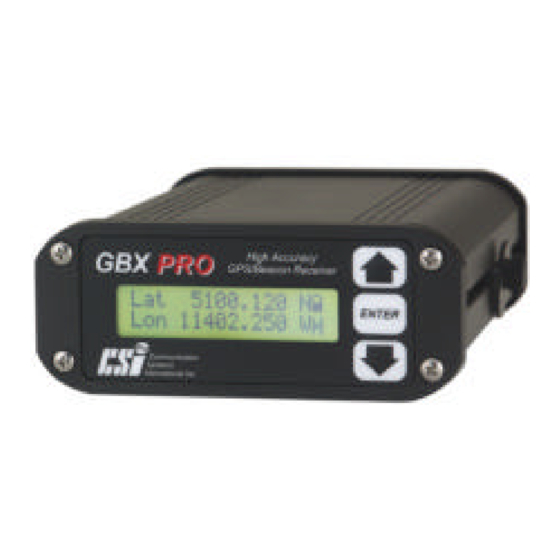
GBX-PRO: Ashtech G-12 High-Accuracy, 12-channel GPS receiver (horizontal accuracy is < 1 meter 95%) Also embedded within the GBX is CSI Wireless’s 300 kHz SBX-2 dual channel, minimum shift keying (MSK) demodulator. It receives GPS correction information broadcast by 300 kHz DGPS radiobeacons. The SBX-2 communicates these corrections to the internal GPS engine where they are used to calculate differentially corrected GPS positions. -
Page 31: Antenna Signal Combiner
E-field Whip antenna. The MGL-3 receives beacon signals that are band-pass filtered and amplified, allowing only radiobeacon frequencies to be passed on to the beacon receiver inside the GBX. The L1 GPS patch antenna features a low noise amplifier, allowing the use of antenna cable lengths up to 10 meters (RG-58U). - Page 32 GBX Reference Manual...
-
Page 33: Installation
2. Installation This chapter contains instructions and recommendations for the installation of the GBX receiver and MGL-3 antenna. 2.1 System Parts List The following list of standard equipment is included with the GBX Receiver system: GBX Receiver MGL-3 Antenna Power Cable... -
Page 34: Installing The Gbx Receiver
The Universal Mounting Bracket (U-bracket) supplied with the GBX is used to secure the receiver to the selected mounting surface. You may install this bracket from either the top or the bottom of the GBX using the thumbscrews provided. The U-bracket allows you to tilt the GBX up or down to achieve the best viewing angle. -
Page 35: Environmental Considerations
2.3.3 Power Considerations The GBX possesses a 2-conductor, positive locking, circular connector for application of power. The GBX accepts an input voltage between 9 and 40 VDC. For best performance, the supplied power should be continuous and clean. The back-lit LCD display of the GBX remains illuminated while power is applied. -
Page 36: Grounding The Gbx
You may command the GBX to any of four distinct operating modes that dictate the input/output state of the receiver (Refer to Section 3.2). The data port is located at the back panel of the GBX and is a DB9 socket connector. -
Page 37: Figure 2-2 Figure 2-2 Gbx Socket Connector Pin Numbering
• Connect Pin-2-TXA of the GBX to the receive pin of the monitor • Connect Pin-3-RXA of the GBX to Tx of the monitor device if bi-directional communication is required • Connect Pin-5-Common Ground of the GBX to the signal return or common ground of the external device. -
Page 38: Gbx-Pro Secondary Serial Port
2.4 GBX-PRO Secondary Serial Port The secondary serial port (Port B) of the G12 GPS engine inside the GBX-PRO is routed to the external data connector located on the rear panel. As indicated in Table 2-2, the transmit line of the secondary serial port of the G12 is available on pin 6, while the receive line is available on pin 8. -
Page 39: Installing The Mgl-3 Antenna
• The position calculated by the GBX is measured to the center of the CDA-1 antenna. Install the antenna in the best location for your application, such as the centerline of your vehicle or vessel. -
Page 40: Antenna Installation
¾ NPT or pipe threads. An optional magnetic mount and 5/8 inch Survey Adapter are available from CSI Wireless. Thread the MGL-3 antenna onto the mount, tightening by hand only. Do not use any tools for tightening, and do not over-tighten. -
Page 41: Routing And Securing The Antenna Cable
• Secure along the cable route using plastic tie wraps. 2.5.4 Connecting the MGL-3 Antenna The MGL-3 antenna connects to the GBX receiver using the supplied TNC-male to BNC-male antenna cable. To connect the CDA-1 antenna to the GBX: Thread the TNC end of the TNC to BNC antenna extension cable onto... -
Page 42: Optional Accessories
Port 1 and Port 2. Port 1 maintains the same RS-232 pin-out as the main serial port on the rear panel of the GBX and is a female DB9 connector. The Port 2 connector accepts correction input to the GBX,... -
Page 43: Table 2-3 'Y' Data Cable Pin-Out (Pn 051-0009-000)
2 with a signal ground on pin 5, and is a male DB9 connector. (CSI Wireless PN 051-0009-000) The GBX-PRO is designed such that the transmit line of the secondary serial port of its internal G12 GPS receiver (Port B) is connected to pin 6 of the DB9 connector located on the rear panel. - Page 44 GBX Reference Manual...
-
Page 45: Configuration And Operation
GBX menu system, configuring operating parameters and viewing status information. Figure 3-1 shows the display and keypad of the GBX. The top line of the display is the active Focus Line for keypad operations. Figure 3-1 GBX Display and Keypad Note - The top line of the GBX display is the Focus Line. -
Page 46: Gbx Operating Modes
Appendix B for further information. 3.2.2 Gx-E – GPS / External Correction Receiver Mode The GBx mode is the primary, and default mode of GBX operation. . In this mode, the GBX receiver differentially corrects its GPS position GBX Reference Manual... -
Page 47: Bx - Beacon Receiver Mode
3.2.3 Bx – Beacon Receiver Mode In Bx mode, the GBX acts as a stand-alone 300 kHz DGPS beacon receiver and outputs RTCM messages to an external GPS receiver. Access is limited to information related to beacon receiver operation and configuration. -
Page 48: Receiver Lock Indication
GBX. 3.3.1 Position Fix Status The GBX provides an indication of the GPS lock status, as contained within the $GPGGA message string output from the data port of the receiver. This indicator is located in the lower right hand corner of the GBX display. -
Page 49: Beacon Lock Status
The lock symbol, illustrated in Figure 3-3, remains in the closed position when the GBX is locked to an RTCM signal, and open, when no broadcast is available for the specified frequency and/or MSK bit rate. -
Page 50: Factory Default Parameters
Figure 3-4 Gx-E External RTCM Source Indicator 3.4 Factory Default Parameters Tables 3-1, 3-2, and 3-3 identify the GBX configuration settings that are required for correct operation of the various GBX Series receivers. These configuration parameters are preset at the factory prior to shipment. -
Page 51: Beacon Receiver Tune Modes
GGA, GSA, SAT, VTG, ZDA 3.5 Beacon Receiver Tune Modes The GBX may be operated in either Automatic or Manual Tune mode. In Automatic Beacon Search (ABS) mode, the receiver will automatically identify and tune to the station providing the strongest DGPS signal. -
Page 52: Manual Mode
GBX to identify the correct MSK bit rate on its own. This mode of operation is most useful when working in an area where you know the... -
Page 53: Beacon Receiver Performance - Snr Reading
The GBX also provides the capability to select a beacon by name from the World Beacon Table stored within receiver memory. You can update this table via the GBX serial port, as detailed in Section 3.8. You may also construct a custom User list of up to 10 beacons, as described in Section 3.7, allowing quicker access to the beacons that... -
Page 54: Gbx Menu System
Position Following initialization, the receiver proceeds directly to the Status branch of the menu tree if the GBX is in GBx, Gx-E, or Bx-E mode. When operating in Bx mode, the GBX will proceed directly to the Beacon Status branch of the menu tree. -
Page 55: Figure 3-5 Gbx Menu System
Country Beacon Name Hgt Unit Subscription User Select User User Entry Vel Unit Version Display Back Edit User User Entry UTC Offset Back Erase User POS Update Back GPS NMEA ON/OFF Back Figure 3-5 GBX Menu System GBX Reference Manual... -
Page 56: Position Status Menu - Gbx, Gx-E, And Bx-E Mode
3.7.2 Position Status Menu – GBx, Gx-E, and Bx-E Mode Position Status section of the menu tree provides access to GPS position and navigation status information. ← 5 1 4 6 . 2 3 4 2 Focus Line 1 1 4 0 3 . 1 4 3 1 H g t 1 0 3 9 . - Page 57 Displays the Horizontal Dilution of Precision (HDOP). H D O P H D O P This information is parsed from the NMEA $GPGGA message. Returns the GBX to the previous menu level. B a c k B a c k GBX Reference Manual...
-
Page 58: Satellites Menu - Gbx, Gx-E, And Bx-E Mode
3.7.3 Satellites Menu – GBx, Gx-E, and Bx-E Mode Satellites section of the menu tree provides access to GPS satellite information. Pressing the keys allows you to scroll Ch01 through the available GPS receiver channels, numbered through Ch12 ← C h 0 1 - S V 1 5... -
Page 59: Beacon Status Menu - Gbx, Bx, And Bx-E Mode
Frequency in kilohertz (kHz) to which the GBX is tuned. S t n n MSK bit rate in bits per second (bps) at which the GBX is demodulating RTCM data. Signal Strength in dBµV/m; SS = 20 is 10 µV/m... -
Page 60: Setup Menu - All Modes
Returns the receiver to the last viewed menu. B a c k B a c k 3.7.5 Setup Menu – All Modes Setup section of the menu tree provides access to GBX configuration information and sub-menus. ← O p t i o n s Focus Line... - Page 61 Pressing with this line in focus sets the GBX to ABS mode, erasing the stored Global Search Table and forcing a new Global Search. Auto Bx Search Selecting will erase the Global Search Table. T u n e T u n e 3 2 5 .
-
Page 62: Options Menu - All Modes
B a u d R a t e B a u d R a t e Baud rate at which the GBX communicates through the Port A of its external bi-directional DB-9S data connector (Pins 2 and 3). Change this parameter to match the baud rate of the external device with which the GBX is communicating. - Page 63 RTCM and NMEA status messages to an external GPS device. Bx-E Beacon receiver mode of operation in which the GBX will output RTCM correction data to an external GPS receiver and display GPS position, navigation, and satellite data as input from an external GPS device (GGA, VTG, ZDA, GSV NMEA message input required).
- Page 64 The change to 5 Hz is saved for subsequent power cycles. When changing from 5 Hz to 1 Hz, the default GPS NMEA messages are output by the GBX. The change to 1 Hz and the default NMEA messages are saved for subsequent power cycles.
-
Page 65: Configuring The Receiver
The following subsections provide detailed instructions for you to configure important operating parameters of the GBX. 3.8.1 Change Baud Rate To modify the baud rate of the GBX data port (P1-Main) (Refer to Figure 3-5): • Navigate to Options in the Setup menu and press •... -
Page 66: Set To Automatic Beacon Search Mode
3.9 User Defined Beacon Table The GBX provides the facility to generate and store a User Table of up to ten frequently used stations. You may use the receiver display and keypad to create this convenient reference selecting individual entries from the Global Beacon listing within receiver memory. -
Page 67: Firmware Updates
GBX receiver. Firmware releases include a Field Upgrade Program, installation instructions, and release notes. There are two versions of firmware installed within the GBX. The first is for the beacon receiver (P003 parent number) and the second is for the micro-controller that runs the menu system and controls serial port operations, referred to as the XBX-3 (P012 parent number). -
Page 68: Gps Nmea 0183 Messages
4. GPS NMEA 0183 Messages The internal GPS receiver of the GBX supports the output of a variety of NMEA data messages. This chapter presents the commands used to activate or deactivate the various messages, and defines the message contents. -
Page 69: Csi Wireless Gps Command Center
PC computer. You may type these commands into the terminal window once you have matched the communication parameters between the terminal program and the GBX. You must ensure that when you press the Enter key on your PC or terminal device to send a command, it represents both a carriage return <CR>... -
Page 70: Gbx-8A Message Activation
$PASHS,SAV,Y<CR><LF> 4.5 GBX-12C Message Activation The Canadian Marconi SuperStar 12-channel GPS engine contained within the GBX-12C uses one command to set the various NMEA messages output by the receiver. This command has the following format: $PMCAG,005,1,x,y<CR><LF>... -
Page 71: Gbx-12R Message Activation
4.6 GBX-12R Message Activation The Rockwell Jupiter 12-channel GPS engine contained within the GBX-12R uses two commands to set the various NMEA messages output by the receiver. These commands have the following format: On - $PRWIILOG,x,A,U,1,<CR><LF>... -
Page 72: Gbx-Pro Message Activation
= A for TXA (Pin-2), and p = B for TXB (Pin-6). The y field is the activation status, where y = ON or y = OFF. To change the update rate of the NMEA messages from the GBX-PRO, use the following command: $PASHS,NME,PER,p<CR><LF>... -
Page 73: Gps Receiver Nmea Data Messages
In this section, GGA, GLL, GSA, GSV, RMC, SAT, VTG, and ZDA NMEA data messages are defined. Note - By default the GBX is configured to output the GGA, GSA, GSV (or SAT for GBX-PRO), VTG, and ZDA (RMC for GBX-12R) messages. -
Page 74: Gll Data Message (All Except Gbx-12R)
<CR><LF> Carriage return and line feed 4.8.2 GLL Data Message (All Except GBX-12R) The GLL message contains Latitude and Longitude information. In Table 4-3, the GLL data message is broken down into its components. This message has the following format: $GPGLL,ddmm.mmmm,s,dddmm.mmmm,s,hhmmss.ss,s*cc<CR><LF>... -
Page 75: Gsv Data Message
Total number of satellites in view Satellite number Elevation in degrees, ee = 0 to 90 Azimuth (true) in degrees, aaa = 0 to 359 SNR (dB), ss = 0 to 99 Checksum <CR><LF> Carriage return and line feed GBX Reference Manual... -
Page 76: Rmc Data Message
Variation sense v = E = East, v = W = West Checksum <CR><LF> Carriage return and line feed 4.8.6 SAT Data Message (GBX-8A and GBX-PRO Only) The SAT message contains GPS satellite tracking status information. Table 4-7 breaks down the SAT data message into its components. -
Page 77: Vtg Data Message
Magnetic course over ground Indicator, always c = M ggg.gg Speed over ground, 000 to 999 knots Speed over ground units, u = N = Nautical mile/h ggg.gg Speed over ground, 000 to 999 km/h Speed over ground units, u = K = kilometer/h GBX Reference Manual... -
Page 78: Zda Data Message (All Except Gbx-12R)
Checksum <CR><LF> Carriage return and line feed 4.8.8 ZDA Data Message (All except GBX-12R) The ZDA message contains Universal Time information. Table 4-9 breaks down the ZDA data message into its components. This message has the following format: $GPZDA,hhmmss.ss,dd,mm,yyyy,xx,yy*cc<CR><LF> Table 4-9 ZDA Data Message Defined... - Page 79 GBX Reference Manual...
-
Page 80: Gbx Nmea 0183 Messages
This chapter identifies the selection of valid NMEA 0183 command and status messages appropriate to the beacon receiver functions of the GBX and the internal processor that operates the menu system. 5.1 GBX Supported Messages Table 5-1 GBX Supported NMEA Messages... -
Page 81: Gbx Beacon Commands
Descriptions of the response messages specific to each command and query are provided below the related command in the following sections. If no response is issued by the GBX for a particular message, an ‘N/A’ field follows in the Response line. - Page 82 When power to the GBX is removed and reapplied, the status output interval resets to zero (no output). The status message output by the GBX, as initiated using this command, is the CRMSS message response discussed in Section 5.4.1.2. Note - If the ‘n’ field in this message is non-zero, the status data message output by the GBX may interrupt the flow of RTCM messages to the GPS receiver.
- Page 83 GBX may interrupt the flow of RTCM messages to the GPS receiver. Re-power the GBX to stop the output of the $CRMSS message, or re-tune the GBX with the ‘n’ field set to zero. 5.3.1.3 Automatic Beacon Search Command ($GPMSK)
-
Page 84: Proprietary Commands
GPS receiver. Re-power the GBX to stop the output of the $CRMSS message, or re-tune the GBX with the ‘n’ field set to zero. 5.3.2 Proprietary Commands The following subsections describe the selection of CSI Wireless proprietary NMEA 0183 formatted commands, and their responses. -
Page 85: Table 5-2 Gbx Baud Rates
5.3.2.3 GBX Host Port Rate Command ($PCSI,6) The GBX Port Rate command sets the communication baud rates of the one external (P1-Main) and three internal (P2-GPS, P3-DGPB, P4- DGPA) GBX micro-controller ports. The command has the following form: $PCSI,6,r <CR><LF>... -
Page 86: Table 5-3 Gbx Factory Pre-Configured Baud Rates
GBX is communicating. P2-GPS {1200, 2400, 4800, or 9600 baud} Matches the GBX micro-controller communication port rate to that of the GPS receivers primary bi-directional communications port. Refer to Table 5-3 for pre- configured settings. -
Page 87: Gbx Beacon Queries
In this message, m designates the GBX Operating Mode, and may be selected from the Table 5-3. Upon commanding the GBX to a new mode of operation, power the receiver down for 10 seconds before applying power again. Table 5-4 GBX Operating Modes... -
Page 88: Proprietary Queries
MSK rate selection (M = manual tune mode, A = automatic tune mode) Period of output of performance status message, 0 to 100 seconds ($CRMSS) 5.4.1.2 Receiver Performance Status Query ($GPCRQ) This standard NMEA query prompts the GBX receiver for its performance status: $GPCRQ,MSS<CR><LF>... - Page 89 $PCSI,4 ->Wipe Search $PCSI,5 ->GPS<>SBX2 Port Rate,<P4> $PCSI,6 ->XBX3 Port Rates,<P1>,<P2>,<P3>,<P4> $PCSI,7 ->XBX3 Mode Note – The $PCSI,5 command is reserved for factory configuration of the GBX and its internal components, and should not be used in the field. GBX Reference Manual...
-
Page 90: Troubleshooting
6. Troubleshooting Use the following checklist to troubleshoot anomalous GBX receiver operation. Table 6-1 provides a problem symptom, followed by a list of possible solutions. Table 6-1 Troubleshooting Symptom Possible Solution • Receiver fails to power Verify polarity of power leads •... - Page 91 Verify GPS receiver DGPS configuration (GBX-8A & GBX-PRO only) • No GBX response to NMEA Verify baud rate settings of GBX and terminal commands and queries device (GBX default baud rate = 4800 baud) • Verify P1, P2, P3, and P4 port rates are consistent with Table 5-3.
-
Page 92: Appendix A - Specifications
Frequency 1.575 GHz Channels 8 or 12 Horizontal Accuracy < 1 meter (GBX-PRO), < 5 meters * Please contact CSI Wireless for detailed GPS receiver specifications. Internal Beacon Engine Operational Specifications Item Specification Frequency Range 283.5 - 325 kHz Channels 2.5 µV/m for 10 dB SNR @ 100 bps MSK Rate... - Page 93 Power Connector Circular 2-pin Locking Plug Mechanical Characteristics Item Specification Enclosure Extruded Aluminum with Aluminum Front and Back Plates. Length GBX-PRO 163 mm (6.4”) Others 150 mm (5.9“) Width 125 mm (4.9”) Height 51 mm (2.0”) Weight 0.64 kg (1.4 lb)
-
Page 94: Table A-2 Mgl-3 Combined Loop / Gps Antenna Specifications
Humidity 100% Condensing Table A-3 External Signal Combiner Specifications Insertion Loss Item Specification J2-J3, Beacon Antenna Port 5 dB nominal, 7 dB max. J2-J1, GPS Antenna Port 0.1 dB nominal, 0.2 dB max. Power Specification Item Specification GBX Reference Manual... -
Page 95: Figure A-1 External Signal Combiner
Port J1 Output Voltage +10 VDC to Beacon antenna Port J2 Input Voltage +10 VDC from GBX +5 VDC ± 5% to GPS antenna Port J3 Output Voltage Mechanical Characteristics Item Specification Enclosure Cast Aluminum Length 92 mm (3.6”) Width 56 mm (2.2”) -
Page 96: Appendix B - Gbx Connectivity
Section 3.6 for instructions related to setting the GBX baud rate. GBx Operating Mode The GBx operating mode is the two primary mode of operation for the GBX. The data output from the GBX in this mode is differentially corrected GPS NMEA data. -
Page 97: Figure B-1 Gbx Mode Interface
• Connect Pin-2-TXA of the GBX to the receive pin of the monitor • Connect Pin-3-RXA of the GBX to TX of the monitor device if bi-directional communication is required • Connect Pin-5-Common Ground of the GBX to the signal return or common ground of the monitor. -
Page 98: Figure B-2 Gx-E Mode Interface
To establish communications between the GBX and an external GPS receiver when in Bx mode, you must: • Connect Pin-2-TXA of the GBX to the receive pin of the GPS receiver • Connect Pin-5-Common Ground of the GBX to the signal return or common ground of the monitor. -
Page 99: Figure B-3 Bx Mode Interface
To establish communications between the GBX and an external GPS receiver when in Bx-E mode, you must: Connect Pin-2-TXA of the GBX to the receive pin of the GPS receiver Connect Pin-3-RXA of the GBX to TX of the monitor device Connect Pin-5-Common Ground of the GBX to the signal return or common ground of the monitor. -
Page 100: Figure B-4 Bx-E Mode Interface
GBX Rear Panel External Device 5 G N D 5 G N D G N D G N D 3 R X 3 R X N M E A N M E A TX TX 2 TX 2 TX RTCM... - Page 101 GBX Reference Manual...
-
Page 102: Appendixc - Beacon Information
• Reference station ID • Field Strength • Operating notes This document is viewable within your Internet browser, however, if you require a faxed copy of this information, contact your CSI Wireless dealer or CSI Wireless Sales. GBX Reference Manual... - Page 103 GBX Reference Manual...
-
Page 104: Further Reading
1800 Diagonal Rd, Suite 600, Alexandria, VA, 22314-2840 USA, Tel: +1- 703-684-4481, Fax: +1-703-836-4429 US Department of Transportation, United States Coast Guard, Broadcast Standard for the USCG DGPS Navigation Service, COMDTINST M16577.1, April, 1993, 2100 Second St. SW, Washington, D.C., 20593-0001, USA GBX Reference Manual... - Page 105 GBX Reference Manual...
-
Page 106: Index
$PCSI,4, 61 Data, 14 $PCSI,5, 61 Power, 14 $PCSI,6, 62 Connectivity, 11, 14, 15, 73, 74, 75, 76 $PCSI,7, 63 CSI Wireless Encryption, 38 $PMCAG, 47, 48 Customer Service, xix $PMOTG, 46 $PRWIILOG, 48 DGPS Errors, 6 Age of Correction, 7... - Page 107 H-Field Loop Antenna, 18 NMEA 0183, 45 Humidity, 13 NMEA 0183 Beacon Command, 58 Automatic Beacon Search, 60 Full Manual Tune, 58 GBX Host Baud Rates, 62 IALA, 5 Partial Manual Tune, 59 ICD-GPS-200, 3 Reserved, 61 ID, 36 Wipe Search, 61...
- Page 108 Operating Mode, 39 Manual, 31, 37, 41 Bx, 25, 39, 75 Tune Modes, 28 Bx-E, 25, 39, 42, 76 Automatic, 29, 30 GBx, 15, 24, 39, 42, 73 Manual, 30 Gx-E, 24, 39, 74 U-Bracket, 12 Power Cable Fuse, 14 UTC, 34...
- Page 109 GBX Reference Manual...
Need help?
Do you have a question about the GBX and is the answer not in the manual?
Questions and answers