Table of Contents
Advertisement
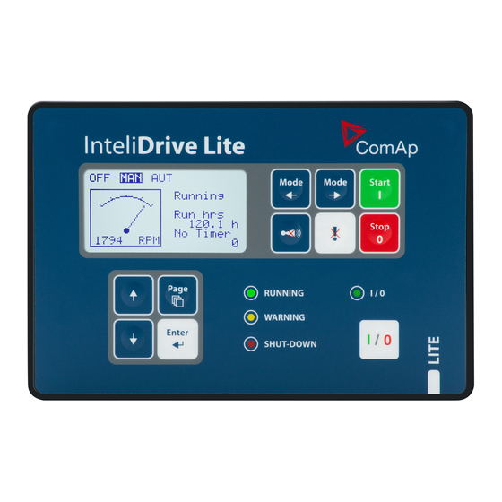
InteliDrive
FLX LITE
SW version 2.5.0
Copyright © 2019 ComAp a.s.
Written by Jaroslav Juriga
Prague, Czech Republic
ComAp a.s., U Uranie 1612/14a,
170 00 Prague 7, Czech Republic
Tel: +420 246 012 111
E-mail: info@comap-control.com, www.comap-control.com
Engine Controller for Pumps
and Compressors
Global Guide
8
11
16
17
36
75
83
90
92
Advertisement
Table of Contents

Related Manuals for ComAp InteliDrive FLX LITE


Summary of Contents for ComAp InteliDrive FLX LITE
-
Page 1: Table Of Contents
4 Installation and wiring 5 Controller setup 6 Troubleshooting 7 Communication 9 Technical data 10 Appendix Copyright © 2019 ComAp a.s. Written by Jaroslav Juriga Prague, Czech Republic ComAp a.s., U Uranie 1612/14a, 170 00 Prague 7, Czech Republic Global Guide Tel: +420 246 012 111 E-mail: info@comap-control.com, www.comap-control.com... - Page 2 Table of contents 1 Document information 1.1 Clarification of notation 1.2 About this guide 1.3 Legal notice 1.4 Document history 1.5 Language support 2 System overview 2.1 Warnings 2.2 General description 2.3 Configurability and monitoring 2.3.1 Open connection from LiteEdit 2.3.2 Open connection from web browser 2.3.3 Open connection from WinScope 3 Applications overview...
- Page 3 4.6.3 IL-NT-RD Wiring 4.6.4 IGL-RA15 (EM2IGLRABAA, EM2FPCRAEAA) 4.6.5 IB-NT 4.7 How to install 4.7.1 Grounding 4.7.2 Wiring 4.7.3 Power supply 4.7.4 Power supply fusing 4.7.5 Binary output protections 4.7.6 Magnetic pick-up 5 Controller setup 5.1 Analog inputs 5.1.1 Table of controller analog inputs 5.1.2 Table of analog inputs options 5.1.3 Connection of InteliDrive Lite analog inputs 5.1.4 Current output transducers...
- Page 4 5.13 MEASUREMENT screens description 5.13.1 Main measure screen 5.13.2 InteliDrive Lite Analog inputs screens 5.13.3 IL-NT-AIO Analog inputs screen 5.13.4 InteliDrive Lite Binary inputs 5.13.5 InteliDrive Lite Binary outputs 5.13.6 IL-NT-BIO8 Binary inputs screen 5.13.7 IL-NT-IO1 Binary inputs screen 5.13.8 ECU State 5.13.9 ECU Values 5.13.10 Statistic 5.13.11 ECU AlarmList...
- Page 5 Speed switch 5.15.11 AUT mode: Engine regulation by RPM control – overview Functions 3 and 4 Functions 3 and 4 setpoints Functions 3 and 4 examples Pressure by RPM control via J1939 Pressure by RPM control via Analog output 6 Troubleshooting 6.1 Alarm management 6.1.1 Sensor fail (Fls) 6.1.2 Warning (Wrn)
- Page 6 10.1.1 Setpoints List of setpoint groups Password EnterPassword ChangePassword List of setpoints Group of setpoints: Basic settings Group of setpoints: Communication Settings Group of setpoints: Engine parameters Group of setpoints: Regulator Group of setpoints: Load limit Group of setpoints: Engine protection Group of setpoints: Date/Time Group of setpoints: Sensors Spec Group of setpoints: AIO module...
- Page 7 10.2.3 IL-NT S-USB (optional card) 10.2.4 IB-Lite (optional card) 10.2.5 IL-NT GPRS (optional card) 10.2.6 IL-NT AOUT8 (optional card) 10.2.7 IL-NT AIO (optional card) 10.2.8 IL-NT IO1 (optional card) 10.2.9 IL-NT BIO8 (optional card) 10.2.10 IGL-RA15 (Remote Annunciator) ID-FLX Lite Global Guide...
-
Page 8: Document Information
Official version of the ComAp’s End User's Guide/Manual is the version published in English. ComAp reserves the right to update this End User's Guide/Manual at any time. ComAp does not assume any responsibility for its use outside of the scope of the Terms or the Conditions and the License Agreement. - Page 9 ComAp, but by following them the cyber-attacks can be considerably reduced and thereby to reduce the risk of damage. ComAp does not take any responsibility for the actions of persons responsible for cyber-attacks, nor for any damage caused by the cyber-attack. However, ComAp is...
-
Page 10: Document History
1.7.0 5.5.2013 Jaroslav Juriga Note: ComAp believes that all information provided herein is correct and reliable and reserves the right to update at any time. ComAp does not assume any responsibility for its use unless otherwise expressly undertaken. 1.5 Language support ID-Lite controllers support different languages. -
Page 11: System Overview
ID-Lite provides gas engine support without ventilation. Controller supports WebSupervisor system. This system enables engine fleet and assets management as well as pure monitoring. Visit www.comap-control.com www.websupervisor.net for more details about WebSupervisor. -
Page 12: Configurability And Monitoring
Server, WebSupervisor, InteliMonitor etc. Process logic – active control of engine, history log, configuration-no programming. 2.3 Configurability and monitoring ID-Lite is using as configuration, monitoring and controlling tool LiteEdit software. For simple configuration, monitoring and controlling can be used InteliMonitor. ID-Lite controller also supports remote monitoring and control via internet, AirGate or cellular network connection. -
Page 13: Open Connection From Web Browser
3. You will see the Control window and you can continue with configuration of Setpoint, inputs, outputs etc. Note: For detail description of LiteEdit and InteliMonitor PC tools see LiteEdit Reference Guide, InteliMonitor Reference Guide InteliDrive Communication Guide. 2.3.2 Open connection from web browser It is possible to connect from a web browser to ID-Lite controllers, mounted with IB-Lite module (or IB-NT with specific conditions) and connected to internet. -
Page 14: Open Connection From Winscope
4. Enter access code and Scada page appears Note: You can try the Web Server from ComAp webpage. The access code is 0. Note: WebSupervisor is possible to use as a control and monitor tool. For access is necessary to be registered. - Page 15 2. Proceed with selection of channels etc. according to WinScope Reference Guide. 6 back to System overview ID-FLX Lite Global Guide...
-
Page 16: Applications Overview
3 Applications overview 6 back to Table of contents Basic wiring scheme for single engine, all engine data are transferred from ECU via CAN J1939 interface in example below. Note: The extension remote annunciator modules can be connected to CAN bus together with ECU. ID-FLX Lite Global Guide... -
Page 17: Installation And Wiring
4 Installation and wiring 4.1 Mounting 4.2 Package contents 4.3 Terminal diagram and dimension 4.4 Extension plug-in modules 4.5 Communication modules 4.6 Remote modules 4.7 How to install 6 back to Table of contents 4.1 Mounting The controller is used to be mounted onto the switchboard door. Requested cutout size is 17 × 112 mm. Use the screw holders delivered with the controller to fix the controller into the door as described on pictures below. -
Page 18: Package Contents
ID-FLX Lite is distributed as ID-FLX-Lite-x.y.iwe package and it is compatible with the PC tool LiteEdit x.y.z and ECU list-x.y, where x, y, z are numbers of software version. Find installation files on ComAp web. Version of published files on the webpage are compatible each other. -
Page 19: Terminal Diagram And Dimension
4.3 Terminal diagram and dimension ID-FLX Lite Global Guide... -
Page 20: Extension Plug-In Modules
4.4 Extension plug-in modules 4.4.1 Extension plug-in modules installation To insert the module, you must open the cover first (use screwdriver to open) and then insert the module into slot. Once you have inserted it, the module will snap under plastic teeth. It is supposed to be installed permanently. - Page 21 Example: Default analog output curves ID-FLX Lite Global Guide...
- Page 22 Example: Wiring for Dacon gauges and IL-NT-AOUT8 ID-FLX Lite Global Guide...
-
Page 23: Il-Nt Aio
4.4.3 IL-NT AIO IL-NT AIO is optional plug-in card. This card offers additional four analog inputs and one analog output. Analog inputs can be use for different types of sensor (resistive, current and voltage) and variable analog output, which can be used as PWM. Adjustment of extension plug-in module is possible via LiteEdit too. Type of analog input is selectable by jumper. -
Page 24: Il-Nt Io1
4.4.4 IL-NT IO1 IL-NT IO1 is optional plug-in card. Through this card controller can drive up to 4 proportional valves and to use 4 additional binary inputs. The 0 V (GND) terminal is internally wired with battery minus internally, the 12-24 V (+Ubat) terminal is wired to battery plus power supply of ID-Lite controller. -
Page 25: Il-Nt Bio8
4.4.5 IL-NT BIO8 IL-NT BIO8 is optional plug-in card. Through this card controller can use up to 8 additional binary inputs or outputs. At least one Batt- terminal has to be connected to battery minus power supply of InteliDrive controller, if at least one binary output is configured. -
Page 26: Il-Nt Rs232-485
Boot jumper programming – In case of interrupted programming or other software failure is possible to use the boot jumper programing to restore controller to working order. Connect the controller to PC, run LiteEdit and wait until connection bar at bottom turns red. Than run programming process via menu Controller -> Programming and cloning –... -
Page 27: Ib-Lite
USB hubs, it can be recognized as new hardware and the drivers are installed again with different number of the virtual serial port. IMPORTANT: Use shielded USB cable only! (ComAp order code: USB-LINK CABLE 1.8 m). 4.5.4 IB-Lite IB-Lite is a optional plug-in card with Ethernet 10 / 100 Mbps interface in RJ45 connector. The card is internally... -
Page 28: Remote Modules
Settings MODEM = module works as standard GSM modem enabling CSD (Circuit Switch Data) connection to controller with LiteEdit or other ComAp PC SW and sending alarm SMSes. Module is usually used for connection to remote monitoring and controlling system WebSupervisor websupervisor.comap.cz... -
Page 29: Il-Nt Rd Software Installation
Remote display software. No further programing of the display is required – unit is self configurable from the main controller. All remote display’s LEDs show the same state as corresponding LEDs on master controller. Front panel buttons on both controllers work in the same way. Engine can be controlled from remote display as well as from master controller. -
Page 30: Il-Nt-Rd Wiring
4.6.3 IL-NT-RD Wiring IL-NT-RD can be connected to ID-Lite controller via RS232 or RS485 communication line. It is possible to connect only up to two remote displays to one master controller, if they are using different communication COMs. It is not supported to connect two or more remote displays to one communication line, eg. RS485. It is possible to monitor only one master controller from one remote display at the time. -
Page 31: Ib-Nt
4.6.5 IB-NT Internet bridge allows different type of communication and multiple controllers communication. Single ID-Lite controller is possible to connect via serial line RS232. For multiple controllers connection is necessary to use RS485 communication port. IB-NT offers direct, internet, AirGate and cellular network type of communication. Note: See the documentation of IB-NT for the detail description. -
Page 32: How To Install
Analog and binary inputs should use shielded cables, especially when length >3 m. Note: During the configuration of controller or setpoints changes is required a password to the controller. The default password from ComAp is “0”. 4.7.1 Grounding To ensure proper function: Use cable min. -
Page 33: Power Supply
4.7.3 Power supply Use minimally power supply cable of 1.5 mm IMPORTANT: Maximum continuous DC power supply voltage is 36 VDC. Maximum allowable DC power supply voltage is 39 VDC. The ID-Lite’s power supply terminals are protected against large pulse power disturbances. When there is a potential risk the controller being subjected to conditions outside its capabilities, an outside protection devise should be used. -
Page 34: Binary Output Protections
Fuse value and type depends on number of connected devices and wire length. Recommended fuse (not fast) type – T1A. Not fast due to internal capacitors charging during power up. 4.7.5 Binary output protections Do not connect binary outputs directly to DC relays without protection diodes, even if they are not connected directly to controller outputs. - Page 35 Check ground connection from pick-up to controllers, eventually disconnect ground connection to one of them Galvanic separate ID-Lite RPM input using ComAp separation transformer RPM-ISO (1:1) Use separate pick-up for Speed governor and ID-Lite. Note: If RPM >2 then the controller is in the state Not ready and the engine will not be allowed to start.
-
Page 36: Controller Setup
5 Controller setup 5.1 Analog inputs 5.2 Binary inputs and outputs 5.3 Analog outputs 5.4 Remote modules - CAN bus connection 5.5 Front panel elements 5.6 Init screens 5.7 Display menus 5.8 How to select the engine mode? 5.9 How to view measured data? 5.10 How to view and edit setpoints? 5.11 How to find active alarms? 5.12 How to list History records? - Page 37 Note: When Engine Control Unit is connected, it is possible to read InteliDrive Analog inputs values AIN1, 2, 3 from CAN bus (J1939). Note: Precision is 4 % ±5 Ω. Note: The nominal range of Analog inputs measuring is 0-10 V (0-40 V), nevertheless the input is able to measure up to 12.5 V (53 V), but with lower precision.
-
Page 38: Table Of Analog Inputs Options
5.1.2 Table of analog inputs options LiteEdit Modify Possibility Not used Analog input isn’t used Type Alarm Analog input is used for monitoring and protection Monitoring Analog input is used only for monitoring … text Up to 14 ASCII characters Name Name in history Up to 4 ASCII characters for the name used in history records... - Page 39 Analog inputs 1, 2, 3, 8 and 9 has separate set points for two levels alarm setting and delay for activation of alarm. Analog input 4, 5, 6 and 7 has special „window“ protection. It is possible to adjust Low and High level with alarm setting Wrn and Sd for each of level.
-
Page 40: Connection Of Intelidrive Lite Analog Inputs
5.1.3 Connection of InteliDrive Lite analog inputs Standard connection of three resistive sensors to analog inputs. Mixed connection of ID-Lite analog inputs: AI1 – binary input AI2 – three state input AI3 – analog resistive input Analog inputs are designed for resistive sensors with resistance in range of 0 Ω to 2.4 kΩ. To ensure a proper function use shielded cables, especially for length over >3 m. -
Page 41: Current Output Transducers
5.1.4 Current output transducers ID-Lite analog inputs are mainly designed for resistor sensors In special case transducers to 4-20 mA output can be used for oil measuring (10.0 Bar or 6.0 Bar). Use predefined 4-20 mA / 100 or 4-20 mA / 60 sensors. This method reduces the input resolution by less than 50% Some types of transducers are not suitable for connection to ID-Lite analog inputs because of influencing by ID- Lite analog input. - Page 42 Recommended values Analog input Curve 0 – 10 V 150 Ω [1 %, 0.5 W] 100 Ω [1 %, 0.5 W] AI 0-10 V.CRV 0 – 30 V 680 Ω [5 %, 2 W] 100 Ω [1 %, 0.5 W] AI 0-30 V.CRV 4 –...
- Page 43 When you finish with adjusting the values click OK and Write to controller. ID-FLX Lite Global Guide...
-
Page 44: Binary Inputs And Outputs
5.2 Binary inputs and outputs ID-FLX Lite Global Guide... -
Page 45: Analog Outputs
5.3 Analog outputs First option is extension plug-in card IL-NT AOUT8. This card provides eight Pulse-With-Modulation (PWM) outputs. These are intended to drive VDO style analog gauges. This is to provide visual indication of typically ECU values without installing additional sensors on the engine. PWM signal emulates sensor which would be typically mounted on the engine. -
Page 46: Default Analog Output Curves
5.3.1 Default analog output curves 5.4 Remote modules - CAN bus connection 5.4.1 Connection rules CAN bus line must be connected in series, from one unit to the next (no star, no cable stubs, no branches) both ends must be by the 120 Ω (internal or external) resistor terminated. Maximal CAN bus length is up to 200 m. ID-FLX Lite Global Guide... -
Page 47: Front Panel Elements
For CAN data cables details see Technical data on page 90 – Communication interface. CAN cable shielding is connected to ID-Lite COM terminal. ID-Lite contains internal fix 120 Ω resistor and must be located on the CAN bus end. It is possible to connect only one remote annunciator to ID-Lite controller. button in LiteEdit Modify window to activate CAN interface. - Page 48 Engine control buttons Number Button Description MODE LEFT button. Use this button to change the mode. The button works only if the main screen with the indicator of currently selected mode is displayed. Note: This button will not work if the controller mode is forced by one of binary inputs Remote OFF, Remote MAN, Remote AUT, Remote TEST.
-
Page 49: Init Screens
LiteEdit PC tool. Note: Init (welcome) screeen appears immediately after power on with ComAp default text. It is possible to modify it using LiteEdit – Configuration – Init button. There is space for 8 text lines per 21 ASCII characters each. -
Page 50: Display Menus
This screen also contains Serial and Pwd. dec. (Password decode) numbers These numbers you can use in case of forgotten passwords. The last line on this screen signalize DiagData number. This number is giving specific diagnostics information in case the program is from some internal reason blocked. Note: If the password for the controller is forgotten, then is necessary to send Serial and Pwd. -
Page 51: How To Change The Display Contrast
5.10.1 How to change the display contrast? Press ENTER and ↑ or ↓ at the same time to adjust the best display contrast. Note: Only in MEASUREMENT screen. 5.10.2 How to check software revision? Hold ENTER and then press PAGE. This activates the panel LED test and controller’s display is switched to Firmware screen. -
Page 52: How To List History Records
Press FAULT RESET accepts all alarms. Non-active alarms immediately disappear from the list. Active alarm list appears on the screen when a new alarm comes up and Main MEASUREMENT screen is active. Note: Alarm list does not activate when you are reviewing the values or setpoints. The second alarm list for ECU alarms is also available. -
Page 53: Intelidrive Lite Analog Inputs Screens
5.13.2 InteliDrive Lite Analog inputs screens First screen Oil pressure (AI1 bargraph with protection limits indication) Water temperature (AI2 bargraph with protection limits indication) Fuel level (AI3 bargraph with protection limits indication) Battery voltage (Power supply bargraph with protection limits indication) Second screen AIN4 (Displayed only if is configured) -
Page 54: Il-Nt-Bio8 Binary Inputs Screen
5.13.6 IL-NT-BIO8 Binary inputs screen IN: BIO8 BI1 Alarm IN: BIO8 BI2 Alarm IN: BIO8 BI3 Alarm IN: BIO8 BI4 Alarm IN: BIO8 BI5 Alarm IN: BIO8 BI6 Alarm IN: BIO8 BI7 Alarm IN: BIO8 BI8 Alarm this line is displayed on the following screen Note: These screens are shown/hidden depending on whether the IL-NT BIO8 is configured or not. -
Page 55: Ecu Values
5.13.9 ECU Values It depends on the ESF file which is configured. See practical example of the screen below for Caterpillar J1939 2.1. Example: Fuel rate L/h or gph CoolantTemp °C or °F IntakeTemp °C or °F Oil pressure Bar or psi Boost pressure Bar or psi Load... -
Page 56: Alarm List
Note: For FMI = 0 and 1, WRN is displayed. For other FMI codes, FLS is displayed. 5.13.12 Alarm list Alarm list displays active or inactive alarms occurred on ID-Lite unit. ID-Lite controller automatically switches to the Alarm list screen when any new Alarm appears, but from Main measure screen only, see Alarm management on page 75. -
Page 57: Display Screens And Pages Structure
5.14 Display screens and pages structure ID-FLX Lite Global Guide... -
Page 58: Functions
5.15 Functions 5.15.1 Engine operation states Engine state Meaning Init Auto test during controller power on Not ready Engine is not ready to start Prestart Prestart time (page 115) sequence in process, Prestart output is closed Cranking Engine is cranking Pause Pause between start attempts Starting... - Page 59 State Condition of the transition Action Next state RPM < 2, Oil pressure not detected, D+ not Not Ready Active, no shutdown alarm active, other than OFF Ready mode selected STARTER on FUEL SOLENOID Prestart Prestart time elapsed Cranking MaxCrank time counter started STARTER off RPM >Start RPM AND BI: Nominal/Idle is active...
-
Page 60: Aut Mode
State Condition of the transition Action Next state FUEL SOLENOID on 192) is active STOP SOLENOID off Running OMINAL PAGE READY TO LOAD off FUEL SOLENOID off RPM = 0 or any other shutdown condition STOP SOLENOID on Shutdown READY TO LOAD off FUEL SOLENOID off Cooling time elapsed Stop... -
Page 61: Engine Timer
5.15.7 Engine timer MAN mode Set the Running timer (page 128). Start engine in MAN mode by START button. Engine stops itself after Running Timer is over. The STOP button cancels timer (forces cooling), the second STOP cancels cooling (forces engine stop). Engine stays running when Running Timer = 0. AUT mode Engine starts and runs all the time when the 189) -
Page 62: Engine Rpm Control In Man Mode
The alarm CoolDown Cd, red color). Its configurable type of alarm, where isn’t necessary immediately to stop the engine. E.g. because of low fuel level can be the engine switched by degrees over cooling time and idle speed. Apart from here above mentioned “ready to wear” basic protections, the user can configure each analog or binary input as a protection. -
Page 63: Engine Rpm Two/Three Levels Switching
Engine RPM two/three levels switching Continuing example above …. closed Speed Sel1 (page 193), Speed Sel2 (page 193), Speed Sel3 (page 193) ramps the Engine RPM to the selected setpoint level. … i.e. switched/ramped to another three levels. Note: If there is more than one Speed Sel Setpoint activated, Speed Sel1 (page 193) has higher priority, then Speed Sel2 (page 193) -
Page 64: Speed Request Chart
Speed request chart 5.15.10 AUT mode: Engine load limitation – overview Functions below can reduce the engine load when is over adjusted limit. Two functions 1 PI loop and 2 Comparator with Hysteresis (CMPH) are available and these functions are described below. -
Page 65: Functions 1 And 2
PI loop and Hysteresis comparator functions can be used for Engine Load Limitation or for any other control function. IMPORTANT: Regulator is working permanently in AUT mode. In table below see different operation conditions. Analog output Binary output Condition LoadLimitAnOut Load switch OFF mode MAN mode... -
Page 66: Functions 1 And 2 Setpoints
Function LoadLimitAOut Analog output of Load Limitation PI control loop. Functions 1 and 2 setpoints Load limit Values ECU: RPM, Load, Load Input CU: AI1-AI9, AIO: AI1-AI4 Load Bias 0 - 10000 [ - ] LoadRequest 1 ±10000 [ - ] LoadRequest 2 ±10000 [ - ] LoadReq Ramp 1 - 10000 [ - ]... -
Page 67: Engine Load Limitation With Analog Output
CU: AI1-AI9 Analog input AIO: AI1-AI4 Binary input LoadRequest2 Input (optional) Binary input LoadRegDisable Binary input RegRequest2 (optional) Binary input R Reg Disable Analog output Load Limit Output (plug-in module) Analog output ByRPMCtrlAout Load Input = Load Load Bias Load Request 1 Load Request 2 Load limit Load ReqRamp... -
Page 68: General Comparator
reduced by Analog output or switched between two levels by Binary output to keep the Engine load on or below the limit. Binary input L Request 2 Input (optional) Binary input Reg Disable Load LimitAnOut Output Analog output (plug-in module) Note: LoadLimitAnOut range = 0 - 10000 Load Input = Load Load Bias... -
Page 69: Engine Load Limitation With On/Off Output
CU: AI1-AI9 Input Analog input AIO: AI1-AI4 Binary output Load Switch Load CMP Input = AI1 Setpoints Load limit Load CMP On = 90 Load CMP Off = 80 Engine load limitation with On/Off output Purpose: Protect the engine against overload by reducing (switching On/Off) the load. Description: CMPH (Comparator with Hysteresis) detect the RPM decrease below the Down limit, activates the Binary output Load switch that reduces (slow down feeder) the load. -
Page 70: Aut Mode: Engine Regulation By Rpm Control - Overview
Input Analog input Binary output Load Switch Load CMP Input = Actual Load Setpoints Load limit Load CMP On = 2000 Load CMP Off = 2200 5.15.11 AUT mode: Engine regulation by RPM control – overview Functions below can automatically change the engine RPM to keep value measured on controller (plug-in module) Analog input (e.g. -
Page 71: Functions 3 And 4
Following example changes the RPM between two levels based on pressure. Functions 3 and 4 Active input RegRequest2 Switch to RegRequest 2 R Reg Disable Set PI Regulator output to R Bias Function Speed Switch Regulator Comparator output ID-FLX Lite Global Guide... -
Page 72: Functions 3 And 4 Setpoints
Functions 3 and 4 setpoints Regulator Values LAI SpeedRequest CU: AI1-AI9 AIO: AI1-AI4 CU: AI1-AI9 Reg Input AIO: AI1-AI4 RPM-BI3 Reg Bias 0 - 10000 Request1 ±10000 Request2 ±10000 Reg Gain ±0.0 - 200.0 % Reg Integral +0.0 % - 100.0 % CU: AI1-AI9 Reg CMP Input AIO: AI1-AI4... -
Page 73: Pressure By Rpm Control Via J1939
Pressure by RPM control via J1939 Actual pressure is measured via Analog input, compared with Requested value and the PI (function 3) output controls the engine RPM via J1939. Binary input Request 2 Input (optional) Binary input R Reg Disable Output Analog output Speed Request... - Page 74 Binary input Request 2 Input (optional) Binary input R Reg Disable Output Analog output Speed Request Reg Input Reg Bias Request Regulator Request 2 Setpoints Reg Gain Reg Integral MinSpeedLim Engine params MaxSpeedLim Speed Ramp 6 back to Controller setup ID-FLX Lite Global Guide...
-
Page 75: Troubleshooting
6 Troubleshooting 6.1 Alarm management 6.2 History file 6.3 Diagnostic messages read from ECU 6.4 Tier 4 diagnostic codes 6 back to Table of contents 6.1 Alarm management Following alarms are available: Sensor fail Warning Cooldown Shut down Note: Type of protection for binary and analog inputs is adjustable in PC tool LiteEdit. In window Modify after double click on input adjust Alarm type. -
Page 76: Shut Down (Sd)
6.1.4 Shut down (Sd) When the shutdown alarm comes up, ID-Lite opens all outputs e.g. FUEL SOLENOID, STARTER and PRESTART to stop the engine immediately. Alarm outputs and common shutdown output are closed. Active or not reset protection disables start. Note: Engine running only alarms are activated after Eng prot del (page 139) , after the engine RPM >... - Page 77 Information on binary Events Protection output available Description specification type (see List of LBO on page 198) Shutdown alarm configurable on the Sd AIO input of plug-in. Configurable Warning/Shutdown Binary input Configurable alarms on the inputs of ID-Lite. If the controller switches off during starting sequence due to bad battery Battery flat condition it doesn’t try to start again...
-
Page 78: History File
Information on binary Events Protection output available Description specification type (see List of LBO on page 198) protection comes active if the running hours of the engine reach this value. Failure of alternator for charging the ChrgAlternFail battery. The protection is active if the output SprinklActive Sprinkler is closed. -
Page 79: Diagnostic Messages Read From Ecu
Abbreviation Historical value ID-Lite analog input 9 value AIM1 Plug-in analog input 1 value AIM2 Plug-in analog input 2 value AIM3 Plug-in analog input 3 value AIM4 Plug-in analog input 4 value binary inputs ID-Lite binary inputs of plug-in BOUT binary inputs ID-Lite Binary output of plug-in ECU alarm Failure Code... -
Page 80: List Of Ecu Diagnostic Codes
6.3.1 List of ECU diagnostic codes Faultcode Diagnostic code Faultcode Diagnostic code Faultcode Diagnostic code ThrottlePos BattPotential PositionSensor AccelPedalPos ElectricalPot TimingSensor FuelDelPress AirInlet Temp J1939 CAN Bus WaterInFuelInd Fuel Temperat InjectorCyl#1 EngineOilLevel EngOil Temp InjectorCyl#2 EngOil Press RatedEngSpeed InjectorCyl#3 CrankcasePress EngineSpeed InjectorCyl#4 Boost Press... -
Page 81: Tier 4 Diagnostic Codes
Faultcode Diagnostic code Faultcode Diagnostic code 0×6200 FanActuator 0×E200 OverheatProt 0×6400 WasteGateAct 0×E600 CoordEmergStop 0×6600 StarterActuatr 6.4 Tier 4 diagnostic codes If the configured ECU supports Tier 4 standard, on the controller screen are displayed supplementary values relative to the DPF status. In ECU list-5.6 supported for John Deere, Cummins CM2250, CM850 and Deutz EMR4. - Page 82 DPF Lamp Active when 3697 = 1 and SPN 3701 = 5 + STOP Yellow Lamp Active when DM1 Yellow lamp is active. Red Lamp Active when DM1 Red lamp is active. 6 back to Troubleshooting ID-FLX Lite Global Guide...
-
Page 83: Communication
7 Communication 6 back to Table of contents ID-FLX Lite Global Guide... -
Page 84: Communication
8 Communication Note: Refer to InteliCommunication Guide for all additional information. 8.1 Direct cable connection ID-Lite can be connected directly with PC via optional communication plug-in modules IL-NT RS232, IL-NT RS232-485, IL-NT S-USB. Use the standard serial / USB cable to connect PC with ID-Lite. In the area with electromagnetic interference should be used shielded cables. -
Page 85: Remote Connection
Manage address setting for each controller in ControllerAddr (page 106). Note: ComAp recommends using galvanicaly separated cable. 8.2 Remote connection 8.2.1 Internet connection ID-Lite controllers can be monitored from PC tools as LiteEdit or InteliMonitor over the Internet using InteliBridge-NT connected to the controller via IL-NT RS232-485 port, via optional IB-Lite plug-in module or via IL-NT GPRS for cellular internet network, see Group: Communication settings on page 106. - Page 86 The complete description of Modbus communication protocol can be found in Modbus Protocol Reference Guide PI-MBUS-300 and Open Modbus Specification Release 1.0. Both documents are available from web site www.modicon.com Example: Request: 01 03 00 35 00 03 15 C5 = Controller address = Modbus function code (Read Multiple Registers) = Register address: Register number (40054) –...
-
Page 87: Ecu Engine Support
Select the proper esl file in LiteEdit->Options->ESL files - typically Allspeed.esl. IMPORTANT: More information about ECU list packages, values, configuration and wiring recommendations can be found in Comap Electronic Engines Support manual. The ID-Lite controller always sends either speed request = 0 % or the IDLE command via J1939 in controller Idle state. -
Page 88: Ecu Analog Inputs
ECU shall show ####, but no alarm is displayed. The output ECU CommOK follows the real situation that means it is not active anytime when the ECU does not communicate. ECU P 218) closes at the beginning of prestart and opens if the engine shall be stopped. ELAY PAGE The engine is started via standard contact output or via CAN bus. -
Page 89: Tier 4 Engines Support
8.7 Tier 4 engines support When the configured ECU supports Tier4 standard, on the controller appears a supplementary screen where are displayed the values relative to the Tier4. Note: Tier4 values Soot Load and Ash Load are visible on ECU screen as well. 6 back to Communication ID-FLX Lite Global Guide... -
Page 90: Technical Data
9 Technical data Power supply Binary outputs Power supply Number of 8-36 V DC range outputs Power supply 100 ms from min. 10 V return to Maximum current 0.5 A drop-out immunity min. 8 V Max switching 36 V DC Power 40-440 mA depend on supply voltage... - Page 91 of Propagation Wire crosscut min. 0.25 mm Maximal attenuation 2 dB / 100 m (at 1 MHz) Recommended Industrial Automation & Process Control Cables: BELDEN (see www.belden.com): 3082A DeviceBus for Allen-Bradley DeviceNet 3083A DeviceBus for Allen-Bradley DeviceNet 3086A DeviceBus for Honeywell SDS 3087A DeviceBus for Honeywell SDS 3084A DeviceBus for Allen-Bradley DeviceNet...
-
Page 92: Appendix
10 Appendix 10.2 Extension modules 6 back to Table of contents ID-FLX Lite Global Guide... -
Page 93: Controller Objects
Controller objects 10.1 List of controller objects types 10.1.1 Setpoints 10.1.2 Values 10.1.3 Logical binary inputs 10.1.4 Logical binary outputs ID-FLX Lite Global Guide... -
Page 94: Setpoints
10.1.1 Setpoints What setpoints are: Configuration of setpoints is possible through panel buttons as is described above or via ComAp PC tool LiteEdit, where the setting can be open by click on the icon List of setpoint groups Group: Basic settings... -
Page 95: List Of Setpoints
IBLite NetMask Load Gain ECU Control IBLite GateIP Load Integral ECU SpeedAdj IBLite DHCP Load CMP Input RetToSpeedAdj ComAp Port Load CMP Off ReliefVal time APN Name Load CMP On MinSpeedLim APN User Name MaxSpeedLim Group of setpoints: APN User Pass... -
Page 96: Group Of Setpoints: Date/Time
Underspeed AIN6 LowDel Date Flow SwitchDel AIN6 HighWrn Timer1Function UnderspeedSd AIN6 HighSd Timer1repeat AIN1 Level 1 AIN6 HighDel Timer1 ON time AIN1 Level 2 AIN7 Level 1 Timer1Duration AIN1 Del AIN7 Level 2 Timer2Function AIN2 Level 1 AIN7 Del Timer2repeat AIN2 Level 2 AIN7 Eval Timer2 ON time... -
Page 97: Group Of Setpoints: Act. Calls/Sms
AnlInAIO1 del AnlInAIO2 del AnlInAIO3 del AnlInAIO4 del Group of setpoints: Act. Calls/SMS Yel Alarm Msg Red Alarm Msg TelNo/Addr Ch1, 2 Group of setpoints: ATT settings Regen Inhibit Regen Force ATT screen 6 back to Controller objects ID-FLX Lite Global Guide... -
Page 98: Group: Basic Settings
Group: Basic settings Engine name Setpoint group Basic settings Related FW 2.5.0 Range [units] Default value Step Comm object 8637 Related applications Description User defined name, used for engine – ID-Lite identification at remote phone or mobile connection. Engine name is maximally 14 characters long and have to be entered using LiteEditsoftware. 6 back to List of setpoints Gear teeth Setpoint group... - Page 99 Comm object 8252 Related applications Description The number of teeth on the engine gear for the pick-up sensor. The setpoint is ignored when ECU is configured. Note: The RPM pickup input is ignored when Engine params: Gear teeth = 0. The engine running state is then detected based on Starting POil (page 114) D+ function (page 122)
- Page 100 RPMbyWterminal Setpoint group Basic settings Related FW 2.5.0 Range [units] 50.00 .. 200.00 [-] Default value Step 0.01 Comm object 8420 Related applications Description The constant of this setpoint multiplies the speed value obtained from the controller input RPM. Note: The default value is and must be 1, when the classical pick-up speed sensor is used to measure the engine speed.
- Page 101 GearTeethBI3 Setpoint group Basic settings Related FW 2.5.0 Range [units] 0 .. 10 [-] Default value Step Comm object 11475 Related applications Description The second RPM (RPM-BI3 value) can be measured in limited frequency range 1 to 50 Hz on Binary input 3. The RPM-BI3 value indicates RPM calculated from BI3 frequency and Basic settings: GearTeeth3 setpoint.
- Page 102 RPM source Setpoint group Basic settings Related FW 2.5.0 Range [units] [Pickup, AIO-AIN1, AIO-AIN2, AIO-AIN3, AIO-AIN4] Default value Step Comm object 12142 Related applications Description Switch from where the RPM is measured. When source is Analog input the converted value is going to be in RPM range.
- Page 103 ControllerMode Setpoint group Basic settings Related FW 2.5.0 Range [units] [OFF, MAN, AUT] Default value Step Comm object 8315 Related applications Description Equivalent to Controller mode changes by MODE→ or ←MODE buttons. Note: Controller Mode change can be separately password protected. 6 back to List of setpoints FltResGoToMAN Setpoint group...
- Page 104 Comm object 12619 Related applications Description Adjust the function of front panel button I/O. Default state Nom/Idle Switches between Nominal and Idle speed request. The function is allowed in MAN mode Nom/Idle only, after reaching the status RUN and the requsted speed set by the setpoint ECU SpeedAdj.
- Page 105 RunHoursSource Setpoint group Basic settings Related FW 2.5.0 Range [units] [ECU, INTERNAL, AUTO] Default value Step Comm object 13345 Related applications Description This setpoint is used for adjustment of RunHours source of the engine. RunHours are all the time read from ECU. INTERNAL RunHours are counted from the inner counter of the controller.
-
Page 106: Group: Communication Settings
Group: Communication settings ControllerAddr Communication Setpoint group Related FW 2.5.0 Settings Range [units] Default value Step Comm object 24537 Related applications Description It is controller’s identification number. It is possible to set controller address different from the default value 1 so that more ID-Lite controllers can be interconnected (via RS485) and accessed e.g. - Page 107 COM2 Mode Communication Setpoint group Related FW 2.5.0 Settings Range [units] [DIRECT/MODBUS/ECU LINK] Default value Step Comm object 24451 Related applications Description Communication protocol switches for the COM2 channel, if dual communication module is plugged in. DIRECT LiteEdit communication protocol via direct cable. MODBUS Modbus protocol.
- Page 108 ModbusComSpeed Communication Setpoint group Related FW 2.5.0 Settings Range [units] [9600, 19200, 38400, 57600] Default value Step Comm object 24477 Related applications Description If the Modbus mode is selected on COM1 or COM2 channels, the Modbus communication speed in bps can be adjusted here.
- Page 109 24374 Related applications Description This sepoint is for adjustment of port for ComAp communication over IB-Lite or IL-NT GPRS module. Standard ComAp port is 23, what is default value of this setpoint. 6 back to List of setpoints ID-FLX Lite Global Guide...
- Page 110 APN Name Communication Setpoint group Related FW 2.5.0 Settings Range [units] Default value Step Comm object 24363 Related applications Description Name of APN access point for GPRS network. Note: This information shall provide your telecommunication operator. 6 back to List of setpoints APN User Name Communication Setpoint group...
- Page 111 Related applications Description AirGate Address. The default address is „airgate.comap.cz“. Note: To reduce the data traffic over cellulat network you can set in setpoint group „Comms Settings“ the parameter „AirGate IP“ = 80.95.108.26. This will save significant data amount needed for translation of AirGate server IP address.
- Page 112 SMTP UserName Communication Setpoint group Related FW 2.5.0 Settings Range [units] Default value Step Comm object 24370 Related applications Description User name or name of e-mail account is used for verification of email sender on SMTP server. If parameter left empty, no verification is expected. It is working for IB-Lite only. 6 back to List of setpoints SMTP UserPass Communication...
- Page 113 Contr MailBox Communication Setpoint group Related FW 2.5.0 Settings Range [units] Default value Step Comm object 24367 Related applications Description E-mail address used as “Sender” of alarm e-mails from IB-Lite. Note: If SMTP server requires verification of sender, e-mail address has to be registered to SMTP server and setpoints “SMTP UserName”...
-
Page 114: Group: Engine Parameters
Group: Engine parameters Starting RPM Setpoint group Engine parameters Related FW 2.5.0 Range [units] 5 .. 1500 [RPM] Default value 350 RPM Step Comm object 9095 Related applications Description “Firing” speed when ID-Lite controller stops cranking (starter goes OFF). Sd Underspeed protection is activated when RPM drops back below the Starting RPM for more than 5 second the engine starting procedure. - Page 115 Prestart time Setpoint group Engine parameters Related FW 2.5.0 Range [units] 0 .. 600 [s] Default value Step Comm object 8394 Related applications Description Time of the PRESTART output closed prior to the engine start – i.e. before the binary outputs Fuel solenoid and Starter are closed and opens when Starting RPM speed is reached.
- Page 116 PreheatTime1 Setpoint group Engine parameters Related FW 2.5.0 Range [units] 0 .. 600 [s] Default value Step Comm object 15987 Related applications Description Defines the shortest time of LBO Preheat activation prior to engine start reached when the measured temperature is PreheatTemp1 (page 115) or higher.
- Page 117 PreheatSensor Setpoint group Engine parameters Related FW 2.5.0 Range [units] OFF/CU: AI1 .. CU: AI9/AIO: AI1 .. AIO: AI4 [-] Default value Step Comm object 15989 Related applications Description This setpoint is used for selection of analog input, which is used for temperature measurement used for variable preheating time calculation.
- Page 118 Idle time Setpoint group Engine parameters Related FW 2.5.0 Range [units] 0 .. 600 [s] Default value Step Comm object 9097 Related applications Description Idle time delay starts when RPM exceeds Starting RPM (page 114). Start fail is detected when during Idle state RPM decreases below 2.
- Page 119 Cooling speed Setpoint group Engine parameters Related FW 2.5.0 Range [units] IDLE, NOMINAL [-] Default value Step Comm object 10046 Related applications Description Selects the function of the Binary output IDLE/NOMINAL during engine Cooling state. IDLE Cooling is executed at Idle speed. NOMINAL Cooling is executed at Nominal speed.
- Page 120 Stop time Setpoint group Engine parameters Related FW 2.5.0 Range [units] 0 .. 240 [s] Default value Step Comm object 9815 Related applications Description Under normal conditions the engine must certainly stop within this period. The period starts by issuing stop command.
- Page 121 FuelSol offset Setpoint group Engine parameters Related FW 2.5.0 Range [units] 0.0 .. 300.0 [s] Default value Step Comm object 10525 Related applications Description This setpoint adjusts the Fuel solenoid output activation in relation to Starter output when Fuel solenoid = GAS.
- Page 122 D+ function Setpoint group Engine parameters Related FW 2.5.0 Range [units] ENABLED, CHRGFAIL, DISABLED [-] Default value DISABLED Step Comm object 9683 Related applications Description The D+ terminal is used for both functions - “running engine” detection and charge ENABLED fail detection.
- Page 123 ECU SpeedAdj Setpoint group Engine parameters Related FW 2.5.0 Range [units] MinSpeedLim (page 124) MaxSpeedLim (page 124) [RPM] Default value 1500 Step Comm object 13095 Related applications Description Enables to adjust engine speed in ECU via CAN bus. Speed request value after the Idle time is over and no other speed selection is activated.
- Page 124 MinSpeedLim Setpoint group Engine parameters Related FW 2.5.0 Range [units] Starting RPM (page 114) MaxSpeedLim (page 124) [RPM] Default value 1200 Step Comm object 10096 Related applications Description The setpoint presets the minimum engine speed in the “Running” operation state. Also see other conditions in the chapter below.
- Page 125 BI Speed Sel 2 Setpoint group Engine parameters Related FW 2.5.0 Range [units] MinSpeedLim (page 124) MaxSpeedLim (page 124) [RPM] Default value 1300 Step Comm object 10523 Related applications Description The setpoint presets the required engine speed during the ‘Speed Sel 2’ binary input is active. Function depends on RetToSpeedAdj (page 123) setting.
- Page 126 Comm object 10148 Related applications Description Any Speed request change is done via this Ramp function. The Ramp via Binary SpeedUp and SpeedDown inputs is dual rate, see below. The Binary inputs SpeedUp and SpeedDown ramp function is for the 0.6s constant 5RPM/s. Does not depend on Engine params: Speed Ramp setting.
- Page 127 0%ofSpeedReq Setpoint group Engine parameters Related FW 2.5.0 Range [units] 0 .. 3000 [RPM] Default value Step Comm object 11125 Related applications Description Limit for Speed Request transformation from RPM to % range for ECU engines using % format. Example: If ECU is configured, then on one of the measurement screen you can see two lines SpeedReq Abs and SpeedReq Rel.
- Page 128 Running timer Setpoint group Engine parameters Related FW 2.5.0 Range [units] 0 .. 1000 [min] Default value Step Comm object 11837 Related applications Description Automatic engine stop in MAN mode or delayed engine stop in AUT mode. Start engine in MAN mode by START button.
-
Page 129: Group: Regulator
Group: Regulator LAI SpdRequest Setpoint group Load limit Related FW 2.5.0 OFF, CU:AI1, CU:AI2, CU:AI3, CU:AI4, CU:AI5, CU:AI6, CU:AI7, CU:AI8, CU:AI9, Range [units] AIO:IA1, AIO:AI2, AIO:AI3, AIO:AI4 [-] Default value Step Comm object 11842 Related applications Description Setpoint is determined for selection of analog input for Speed request in the controller’s MAN mode. Speed request selection is done by binary inputs. - Page 130 Reg Input Setpoint group Load limit Related FW 2.5.0 CU:AI1, CU:AI2, CU:AI3, CU:AI4, CU:AI5, CU:AI6, CU:AI7, CU:AI8, CU:AI9, Range [units] AIO:IA1, AIO:AI2, AIO:AI3, AIO:AI4, RPM-BI3 [-] Default value CU:AI1 Step Comm object 11843 Related applications Description PI loop analog input selection. Source can be adjusted from controller analog inputs or from extension module inputs.
- Page 131 Request 2 Setpoint group Load limit Related FW 2.5.0 Range [units] -10000 .. +10000 [-] Default value Step Comm object 11845 Related applications Description Regulator requested value when LBI Request2 is active. Value of this Setpoint should be given in value of quantity without decimal point. Example: When AIN is configured in such way that Load limit set on 5 V to maintain the value 8.54 bar, then the value inserted to this Setpoint is 854.
- Page 132 Comm object 11847 Related applications Description This setpoint is giving regulator integration factor. See Note below. Note: ID-Lite controllers include PI loop for speed or analog output regulation. The requested value is given by setpoints Request 1 (page 130) Request 2 (page 131).
- Page 133 Reg CMP Input Setpoint group Load limit Related FW 2.5.0 CU:AI1, CU:AI2, CU:AI3, CU:AI4, CU:AI5, CU:AI6, CU:AI7, CU:AI8, CU:AI9, Range [units] AIO:IA1, AIO:AI2, AIO:AI3, AIO:AI4, RPM-BI3 [-] Default value CU:AI1 Step Comm object 11839 Related applications Description This is comparator with hysteresis analog input selection from controller analog inputs or from extension module inputs.
- Page 134 Reg CMP Off Setpoint group Load limit Related FW 2.5.0 Range [units] -10000 .. +10000 [-] Default value Step Comm object 11840 Related applications Description Limit to open the 220). PEED WITCH PAGE Value of this Setpoint should be given in value of quantity without decimal point. Example: When AIN is configured in such way that Load limit set on 5 V to maintain the value 8.54 bar, then the value inserted to this Setpoint is 854.
-
Page 135: Group: Load Limit
Group: Load limit Load input Setpoint group ATT settings Related FW 2.5.0 RPM, ECU:Load, CU:AI1, CU:AI2, CU:AI3, CU:AI4, CU:AI5, CU:AI6, CU:AI7, Range [units] CU:AI8, CU:AI9, AIO:IA1, AIO:AI2, AIO:AI3, AIO:AI4 [-] Default value Step Comm object 11850 Related applications Description This setpoint is for Load limit PI loop analog input selection. Source can be adjusted from controller RPM pick-up, ECU, analog inputs or from extension module inputs. - Page 136 LoadRequest 1 Setpoint group ATT settings Related FW 2.5.0 Range [units] -10000 .. +10000 [-] Default value Step Comm object 11852 Related applications Description Regulator requested value. Value of this Setpoint should be given in value of quantity without decimal point. Example: When AIN is configured in such way that Load limit set on 5 V to maintain the value 8.54 bar, then the value inserted to this Setpoint is 854.
- Page 137 LoadUpLimit Setpoint group ATT settings Related FW 2.5.0 Range [units] 0 .. 10000 [-] Default value 10000 Step Comm object 11855 Related applications Description Load limit regulator PI output upper limit. Value of this Setpoint should be given in value of quantity without decimal point. Example: When AIN is configured in such way that Load limit set on 5 V to maintain the value 8.54 bar, then the value inserted to this Setpoint is 854.
- Page 138 Load Integral Setpoint group ATT settings Related FW 2.5.0 Range [units] 0.0 .. 100.0 [%] Default value Step Comm object 11858 Related applications Description This setpoint is giving Load limit integration factor. 6 back to List of setpoints Load CMP Input Setpoint group Load limit Related FW...
-
Page 139: Group: Engine Protection
Load CMP On Setpoint group Load limit Related FW 2.5.0 Range [units] -10000 .. +10000 [-] Default value Step Comm object 11861 Related applications Description Limit to open 220). WITCH PAGE Value of this Setpoint should be given in value of quantity without decimal point. Example: When AIN is configured in such way that Load limit set on 5 V to maintain the value 8.54 bar, then the value inserted to this Setpoint is 854. - Page 140 Horn timeout Setpoint group Engine protection Related FW 2.5.0 Range [units] 0 .. 600 [s] Default value Step Comm object 8264 Related applications Description Max time limit of horn sounding. Set to zero if you want to leave the output HORN open. Horn timeout starts again from the beginning if a new alarm appears before previous Horn timeout has elapsed.
- Page 141 Comm object 8260 Related applications Description Limit for Warning Underspeed protection. Active protection is indicated as “Wrn Underspeed” in Alarm list. Under speed Warning protection is inactive 5 s after RPM is over Starting RPM (page 114) and during the Idle time.
- Page 142 Comm object 11415 Related applications Description Disables the Wrn Underspeed protection when engine RPM drops below DISABLED Underspeed (page 140) and SdUnderspeed protection in case the engine RPM drops below the Starting RPM (page 114). ENABLED Function as on the picture above. Default state. Tables below describe Underspeed protection behavior depends on Underspeed Sd setpoint setting and RPM value.
- Page 143 AIN1 Level 1 Setpoint group Engine protection Related FW 2.5.0 Range [units] -100.0 .. +1000.0 [Bar] Default value Step Comm object 8369 Related applications Description Warning limit level for ANALOG INPUT 1. 6 back to List of setpoints AIN1 Level 2 Setpoint group Engine protection Related FW...
- Page 144 AIN2 Level 2 Setpoint group Engine protection Related FW 2.5.0 Range [units] -100 .. 10000 [°C] Default value Step Comm object 8376 Related applications Description Shutdown limit level for ANALOG INPUT 2. 6 back to List of setpoints AIN2 Del Setpoint group Engine protection Related FW...
- Page 145 AIN3 Del Setpoint group Engine protection Related FW 2.5.0 Range [units] 0 .. 180 [s] Default value Step Comm object 8377 Related applications Description Delay for ANALOG INPUT 3. Note: Analog input 3 is usually determined to Fuel Level measurement and it is resistive type of input with range 0-2500 Ω.
- Page 146 AIN4 Level 2 Setpoint group Engine protection Related FW 2.5.0 Range [units] 0 .. 10000 [U16] Default value Step Comm object 9272 Related applications Description Shutdown limit level for AIN4. 6 back to List of setpoints AIN4 Del Setpoint group Engine protection Related FW 2.5.0...
- Page 147 AIN4 LowWrn Setpoint group Engine protection Related FW 2.5.0 Range [units] 0 .. 10000 [U16] Default value Step Comm object 13365 Related applications Description Low Warning limit level for AIN4. 6 back to List of setpoints AIN4 LowSd Setpoint group Engine protection Related FW 2.5.0...
- Page 148 AIN4 HighSd Setpoint group Engine protection Related FW 2.5.0 Range [units] 0 .. 10000 [U16] Default value Step Comm object 13369 Related applications Description High ShutDown limit level for AIN4. 6 back to List of setpoints AIN4 HighDel Setpoint group Engine protection Related FW 2.5.0...
- Page 149 AIN5 Del Setpoint group Engine protection Related FW 2.5.0 Range [units] 0 .. 3600 [s] Default value Step Comm object 9276 Related applications Description Delay for Wrn/Sd AIN5 alarm. 6 back to List of setpoints AIN5 Eval Setpoint group Engine protection Related FW 2.5.0 Range [units]...
- Page 150 AIN5 LowSd Setpoint group Engine protection Related FW 2.5.0 Range [units] 0 .. 10000 [U17] Default value Step Comm object 13354 Related applications Description Low ShutDown limit level for AIN5. 6 back to List of setpoints AIN5 LowDel Setpoint group Engine protection Related FW 2.5.0...
- Page 151 AIN5 HighDel Setpoint group Engine protection Related FW 2.5.0 Range [units] 0 .. 3600 [s] Default value Step Comm object 13358 Related applications Description High level protection delay for Wrn and Sd of AIN5. Note: Analog input 5 is fully configurable and it is voltage type of input with range 0-40 V. 6 back to List of setpoints AIN6 Level 1 Setpoint group...
- Page 152 AIN6 Eval Setpoint group Engine protection Related FW 2.5.0 Range [units] NORMAL, CLASS C [-] Default value NORMAL Step Comm object 13076 Related applications Description Protection behaves according to the standard configuration of Wrn/Sd alarm in NORMAL LiteEdit AINx configuration screen. Default state. The protection is type “Running only”...
- Page 153 AIN6 LowDel Setpoint group Engine protection Related FW 2.5.0 Range [units] 0 .. 3600 [s] Default value Step Comm object 13361 Related applications Description Low level protection delay for Wrn and Sd of AIN6. 6 back to List of setpoints AIN6 HighWrn Setpoint group Engine protection...
- Page 154 AIN7 Level 1 Setpoint group Engine protection Related FW 2.5.0 Range [units] 0 .. 10000 [U13] Default value Step Comm object 9262 Related applications Description Warning limit level for AIN7. 6 back to List of setpoints AIN7 Level 2 Setpoint group Engine protection Related FW 2.5.0...
- Page 155 AIN7 Eval Setpoint group Engine protection Related FW 2.5.0 Range [units] NORMAL, CLASS C [-] Default value NORMAL Step Comm object 13077 Related applications Description Protection behaves according to the standard configuration of Wrn/Sd alarm in NORMAL LiteEdit AINx configuration screen. Default state. The protection is type “Running only”...
- Page 156 AIN7 LowDel Setpoint group Engine protection Related FW 2.5.0 Range [units] 0 .. 3600 [s] Default value Step Comm object 13364 Related applications Description Low level protection delay for Wrn and Sd of AIN7. 6 back to List of setpoints AIN7 HighWrn Setpoint group Engine protection...
- Page 157 AIN7 HighDel Setpoint group Engine protection Related FW 2.5.0 Range [units] 0 .. 3600 [s] Default value Step Comm object 13349 Related applications Description High level protection delay for Wrn and Sd of AIN7. Note: In the alarm list is only displayed Wrn/Sd alarm on the appropriate analog input. There is not resolution Low/High alarm.
- Page 158 AIN8 Del Setpoint group Engine protection Related FW 2.5.0 Range [units] 0 .. 180 [s] Default value Step Comm object 9267 Related applications Description Delay for Wrn/Sd AIN8 alarm. Note: Analog input 8 is configurable with basic two levels protection and it is voltage type of input with range 0-10 V.
- Page 159 AIN9 Del Setpoint group Engine protection Related FW 2.5.0 Range [units] 0 .. 180 [s] Default value Step Comm object 9270 Related applications Description Delay for Wrn/Sd AIN9 alarm. Note: Analog input 9 is configurable with basic two levels protection and it is voltage type of input with range 0-10 V.
- Page 160 Comm object 8708 Related applications Description There are two new protections related to RPM-BI3 where functions RPMdiff Sd (page 161), RPMdiff Wrn (page 162) limits depends on setting of GearBoxRatio: Separate RPM-BI3 underspeed Wrn and Sd protection when Engine protect: GearBoxRatio = 0.0 Difference check between RPM and RPM3 with calculation of gear-box ratio, when Engine protect: GearBoxRatio >...
- Page 161 RPMdiff Sd Setpoint group Engine protection Related FW 2.5.0 Range [units] 1 .. 1000 [RPM] Default value 1000 Step Comm object 10143 Related applications Description RPM-BI3 Sd underspeed protection limit or Sd difference limit between RPM-BI3 and RPM transferred via GearBoxRatio (page 159).
- Page 162 RPMdiff Wrn Setpoint group Engine protection Related FW 2.5.0 Range [units] 1 .. 1000 [RPM] Default value 1000 Step Comm object 10141 Related applications Description RPM-BI3 Wrn underspeed protection limit or Wrn difference limit between RPM-BI3 and RPM transferred GearBoxRatio (page 159).
- Page 163 RPMdiff delay Setpoint group Engine protection Related FW 2.5.0 Range [units] 0 .. 600 [s] Default value Step Comm object 10150 Related applications Description Delay for RPMdiff protections above. See description in GearBoxRatio (page 159). 6 back to List of setpoints ID-FLX Lite Global Guide...
- Page 164 BIN1 Prot Del Setpoint group Engine protection Related FW 2.5.0 Range [units] 0 .. 3600 [s] Default value Step Comm object 13078 Related applications Description Seven setpoints are dedicated for separately adjustment of the delay for each of binary inputs according to the Class B protection standard.
- Page 165 BIN4 Prot Del Setpoint group Engine protection Related FW 2.5.0 Range [units] 0 .. 3600 [s] Default value Step Comm object 13081 Related applications Description Seven setpoints are dedicated for separately adjustment of the delay for each of binary inputs according to the Class B protection standard.
- Page 166 BIN7 Prot Del Setpoint group Engine protection Related FW 2.5.0 Range [units] 0 .. 3600 [s] Default value Step Comm object 13084 Related applications Description Seven setpoints are dedicated for separately adjustment of the delay for each of binary inputs according to the Class B protection standard.
-
Page 167: Group: Date/Time
Group: Date/Time Time stamp per Setpoint group Date/Time Related FW 2.5.0 Range [units] 0 .. 240 [min] Default value Step Comm object 8979 Related applications Description This setpoint is dedicated to adjustment of time interval for periodical history records. 6 back to List of setpoints SummerTimeMod Setpoint group Date/Time... - Page 168 Date Setpoint group Date/Time Related FW 2.5.0 Range [units] [DD:MM:YYYY] Default value Step Comm object 24553 Related applications Description Actual date. 6 back to List of setpoints Timer1Function Setpoint group Date/Time Related FW 2.5.0 Range [units] NoFunc, AutoRun, AutoRegCMP, AutoBatt, AutoStop [-] Default value No Func Step...
- Page 169 Timer1repeat Setpoint group Date/Time Related FW 2.5.0 NONE, MONDAY, TUESDAY, WEDNESDAY, THURSDAY, WEDNESDAY, Range [units] FRIDAY, SATURDAY, SUNDAY, MON-FRI, MON-SAT, MON-SUN, SAT-SUN [-] Default value NONE Step Comm object 10045 Related applications Description This setpoint defines 219) activation. 219) is internally linked with IMER PAGE IMER...
- Page 170 Timer2Function Setpoint group Date/Time Related FW 2.5.0 Range [units] No Func, AutoRun, AutoRegCMP, AutoBatt, AutoStop [-] Default value No Func Step Comm object 11661 Related applications Description Operates just corresponding 219) according the 219) IMER PAGE IMER PAGE setting, see Timer2repeat (page 171), Timer2 ON time (page...
- Page 171 Timer2repeat Setpoint group Date/Time Related FW 2.5.0 NONE, MONDAY, TUESDAY, WEDNESDAY, THURSDAY, WEDNESDAY, Range [units] FRIDAY, SATURDAY, SUNDAY, MON-FRI, MON-SAT, MON-SUN, SAT-SUN [-] Default value NONE Step Comm object 10202 Related applications Description This setpoint defines 219) activation. 219) is internally linked with IMER PAGE IMER...
-
Page 172: Group: Sensors Spec
Group: Sensors Spec Calibr AI1 Setpoint group Sensors Spec Related FW 2.5.0 Range [units] -1000 .. +1000 [-] Default value Step Comm object 11919 Related applications Description Calibrate the constant to adjust the measured value of ID-Lite analog inputs. Physical dimension of calibrating constant is corresponding to analog input. - Page 173 Calibr AI4 Setpoint group Sensors Spec Related FW 2.5.0 Range [units] -1000 .. +1000 [-] Default value Step Comm object 11917 Related applications Description Calibrate the constant to adjust the measured value of ID-Lite analog inputs. Physical dimension of calibrating constant is corresponding to analog input. Note: Calibration constants have to be adjusted when measured value is near the alarm level.
- Page 174 Calibr AI7 Setpoint group Sensors Spec Related FW 2.5.0 Range [units] -1000 .. +1000 [-] Default value Step Comm object 11914 Related applications Description Calibrate the constant to adjust the measured value of ID-Lite analog inputs. Physical dimension of calibrating constant is corresponding to analog input. Note: Calibration constants have to be adjusted when measured value is near the alarm level.
- Page 175 Calibr AIO1 Setpoint group Sensors Spec Related FW 2.5.0 Range [units] -1000 .. +1000 [-] Default value Step Comm object 11919 Related applications Description Calibrate the constant to adjust the measured value of plug-in analog inputs. Physical dimension of calibrating constant is corresponding to analog input. 6 back to List of setpoints Calibr AIO2 Setpoint group...
- Page 176 Calibr AIO4 Setpoint group Sensors Spec Related FW 2.5.0 Range [units] -1000 .. +1000 [-] Default value Step Comm object 13640 Related applications Description Calibrate the constant to adjust the measured value of plug-in analog inputs. Physical dimension of calibrating constant is corresponding to analog input. 6 back to List of setpoints CounterConst 1, CounterConst 2 Setpoint group...
-
Page 177: Group: Aio Module
Counter mode 1, Counter mode 2 Setpoint group Sensors Spec Related FW 2.5.0 Range [units] [Always / Running / OFF] Default value Step Comm object 14283 Related applications Description Setting of Counter 1 and Counter 2 mode: Always Corresponding counter counts pulses all time. Running Corresponding counter counts pulses only when engine is running. - Page 178 AnlInAIO3 lev1 Setpoint group AIO module Related FW 2.5.0 Range [units] -100 .. 10000 [-] Default value Step Comm object 13652 Related applications Description The level for il-nt plug-in card Analog input 1, 2, 3, 4 alarm detection. 6 back to List of setpoints AnlInAIO4 lev1 Setpoint group AIO module...
- Page 179 AnlInAIO3 lev2 Setpoint group AIO module Related FW 2.5.0 Range [units] -100 .. 10000 [-] Default value Step Comm object 13656 Related applications Description The level for IL-NT-AIO plug-in card Analog input 1, 2, 3, 4 alarm detection. 6 back to List of setpoints AnlInAIO4 lev2 Setpoint group AIO module...
- Page 180 AnlInAIO2 del Setpoint group AIO module Related FW 2.5.0 Range [units] 0 .. 180 [s] Default value Step Comm object 13659 Related applications Description Configuration Protection Under limit Protection is activated only when measured value is under measured level. Over limit Protection is activated only when measured value is over measured level.
-
Page 181: Group: Act. Calls/Sms
AnlInAIO4 del Setpoint group AIO module Related FW 2.5.0 Range [units] 0 .. 180 [s] Default value Step Comm object 13661 Related applications Description Configuration Protection Under limit Protection is activated only when measured value is under measured level. Over limit Protection is activated only when measured value is over measured level. - Page 182 Red Alarm Msg Setpoint group Act. Calls/SMS Related FW 2.5.0 Range [units] OFF, ON [-] Default value Step Comm object 8484 Related applications Description Set this setpoint to YES if you want to get messages when a red (shutdown) alarm occurs. Note: The target address (cellular network phone number or e-mail address) must be set correctly to the setpoint(s) TelNo/Addr Ch1 resp.
-
Page 183: Group: Att Settings
Group: ATT settings Regen Inhibit Setpoint group ATT settings Related FW 2.5.0 Range [units] Default value Step Comm object 14520 Related applications Description Regen Inhibit – set ECU value Aftertreatment Regeneration Inhibit Switch (SPN 3695). There can be set: OFF – automatic filter regeneration is enabled - SPN 3695 = 00b ON –... - Page 184 ATT screen Setpoint group ATT settings Related FW 2.5.0 Range [units] [Enabled, Disabled] Default value Enabled Step Comm object 16190 Related applications Description This setpoint is used to deactivate Aftertreatment screen. If option Disabled is selected, the Aftertreatment screen will not be displayed even if ECU is configured and controller is receiving Aftertreatment specific frames.
-
Page 185: Values
10.1.2 Values What values are: Values are displayed on the controller screen or are accessible via icon in the LiteEdit PC tool. See the table with all visible values in LiteEdit. Note: Some engine values (*) are visible only if the ECU unit is configured. Groups Name Note... - Page 186 Groups Name Note Binary states are displayed and is Binary I/O BOUT possible to use extract menu button for more details RemoteControl Time Date/Time Date Engine state Timer text Timer val SW version Application SW branch ID info PasswordDecode GSM SignalLvl GSM ErrorRate GSM DiagCode: AirGate Diag:...
-
Page 187: Logical Binary Inputs
10.1.3 Logical binary inputs Note: Any binary input can be configured to any ID-Lite controller terminal or changed to different function by LiteEdit PC tool. There is adjustable delay when any binary input is configured as protection. Binary inputs InteliDrive Lite – default configuration BI1 –... -
Page 188: List Of Lbi
List of LBI Not used Rem start/stop Emergency stop Sprinkler Access lock Remote OFF Remote MAN Remote AUT RemControlLock Emerg. manual StartButton StopButton FaultResButton HornResButton Nominal/Idle Speed Up Speed Down Speed Sel1 Speed Sel2 Speed Sel3 Lang selection Conveyor LoadRequest2 LoadRegDisable RegRequest2 R Reg Disable... - Page 189 Not used Related FW 2.5.0 Related applications Comm object Description Binary input has no function. Use this option when binary input is not connected. 6 back to List of LBI Rem start/stop Related FW 2.5.0 Related applications Comm object Description Binary input is used for external request for engine run in AUT mode only.
- Page 190 Access lock Related FW 2.5.0 Related applications Comm object Description If the input is closed, no setpoints can be adjusted from controller front panel and engine mode (OFF-MAN- AUT) cannot be changed. Note: Access lock does not protect setpoints and mode changing from LiteEdit . To avoid unqualified changes the selected setpoints can be password protected.
- Page 191 Emerg. manual Related FW 2.5.0 Related applications Comm object Description If the input is activated the controller behaves like when switched to OFF mode and opens all binary outputs. There is one exception – Stop solenoid doesn’t activate on this transition. Detection of running engine and subsequent alarm message "Sd Stop fail"...
- Page 192 Nominal/Idle Related FW 2.5.0 Related applications Comm object Description Input works in MAN mode only switching between running states Nominal/Idle. Active Nominal/Idle input activates binary output Idle/Nominal and sends Speed request = Idle speed (page 118) and/or active (binary) IDLE command to the ECU (e.g. to Volvo EMS). Eng state Sped request in MAN mode Sped request in AUT mode...
- Page 193 Speed Sel1 Related FW 2.5.0 Related applications Comm object Description If the input is active, the Speed request = BI Speed Sel 1 (page 124). The function is affected by RetToSpeedAdj (page 123). Note: See Speed request chart (page 64). 6 back to List of LBI Speed Sel2 Related FW...
- Page 194 Lang selection Related FW 2.5.0 Related applications Comm object Description Switch display texts between two languages. 6 back to List of LBI Conveyor Related FW 2.5.0 Related applications Comm object Description Initial condition: Running engine. Rising edge 194) activates 203) Conveyor horn (page 127).
- Page 195 6 back to List of LBI R Reg Disable Related FW 2.5.0 Related applications Comm object Description Active input disables the Regulator PI loop and switches analog output to constant Reg Bias (page 130). 6 back to List of LBI Clear DayCons Related FW 2.5.0...
- Page 196 Prot Test Related FW 2.5.0 Related applications Comm object Description When the new LBI Protection Test is activated (by rising edge), all Sd alarms are for 90 s blocked. The exception is LBI Emergency stop and Overspeed protection. 6 back to List of LBI ID-FLX Lite Global Guide...
-
Page 197: Logical Binary Outputs
10.1.4 Logical binary outputs Note: Any binary input can be configured to any ID-Lite controller terminal or changed to different function by LiteEdit PC tool. There is adjustable delay when any binary input is configured as protection. Binary outputs InteliDrive Lite – default BO1 –... -
Page 198: List Of Lbo
OFF mode List of LBO MAN mode Configuration of binary outputs is feasible easily AUT mode by combo box menu in the configuration window ServiceTime Modify. DEF Tank Level Starter BI1 - stat Fuel solenoid BI2 - stat Stop solenoid BI3 - stat Stop Pulse BI4 - stat... - Page 199 ECU PwrRelay Timer1 Timer2 Glow plugs Conveyor SpeedSwitch LoadSwitch Close Load Toggle RemoteControl1 RemoteControl2 RemoteControl3 RemoteControl4 RemoteControl5 RemoteControl6 RemoteControl7 RemoteControl8 6 back to Controller objects ID-FLX Lite Global Guide...
- Page 200 Starter Related FW 2.5.0 Related applications Comm object Description Closed relay energizes the starter of engine. The relay opens if: The strating speed is reached or Maximum time of cranking is exceeded or Request to stop comes up 6 back to List of LBO Fuel solenoid Related FW 2.5.0...
- Page 201 Stop Pulse Related FW 2.5.0 Related applications Comm object Description Output is active for 1 second after 200) activation. This signal is sent to ECU in case TOP SOLENOID PAGE of engine stop request. 6 back to List of LBO Preheat Related FW 2.5.0...
- Page 202 Prestart Related FW 2.5.0 Related applications Comm object Description The output closes prior to the engine start (Prestart) and opens when Starting RPM (page 114) speed is reached. During repeated crank attempts the output is closed too. The output could be used for pre-glow, pre-heat or prelubrication. 6 back to List of LBO Preglow Related FW...
- Page 203 Air valves Related FW 2.5.0 Related applications Comm object 1247 Description Output closes together with Prestart time (page 115) and opens after the engine is stopped. Stopped engine conditions: RPM = 0, Starting POil (page 114), D+ function (page 122) (if enabled).
- Page 204 Ready Related FW 2.5.0 Related applications Comm object Description The output is closed if following conditions are fulfilled: Engine is not running and No Shut down or Slow stop alarm is active Controller is not in OFF mode 6 back to List of LBO Ready to load Related FW 2.5.0...
- Page 205 ChrgAlternFail Related FW 2.5.0 Related applications Comm object 1260 Description Output closes if engine is running and D+ input not energized. The output opens, if: Alarm is not active and FAULT RESET is pressed Note: Threshold level for D+ input is 80% supply voltage. 6 back to List of LBO Stop failed Related FW...
- Page 206 Underspeed Related FW 2.5.0 Related applications Comm object 1296 Description Output closes if the engine “Sd Underspeed” alarm activates i.e. when RPM is below the Starting RPM (page 114) limit. The output opens, if Alarm is not active and FAULT RESET is pressed 6 back to List of LBO Start failed Related FW...
- Page 207 Common Wrn Related FW 2.5.0 Related applications Comm object Description Output closes when any warning alarm appears. The output opens, if No warning alarm is active and FAULT RESET is pressed 6 back to List of LBO Common Sd Related FW 2.5.0 Related applications Comm object...
- Page 208 Sd Oil Press Related FW 2.5.0 Related applications Comm object Description Output closes if the oil pressure shutdown alarm activates. The output opens, if Alarm is not active and FAULT RESET is pressed 6 back to List of LBO Wrn Oil Press Related FW 2.5.0 Related applications...
- Page 209 Sd FuelLevel Related FW 2.5.0 Related applications Comm object Description Output closes if the Fuel level shutdown alarm activates. The output opens, if Alarm is not active and FAULT RESET is pressed 6 back to List of LBO Wrn FuelLevel Related FW 2.5.0 Related applications...
- Page 210 ServiceTime Related FW 2.5.0 Related applications Comm object Description Output closes if the ServiceTime alarm activates. Service time is adjusted by setpoint NextServTime (page 159). The output opens, if Alarm is not active and FAULT RESET is pressed 6 back to List of LBO DEF Tank Level Related FW 2.5.0...
- Page 211 BI3 - stat Related FW 2.5.0 Related applications Comm object Description In case the binary input is configured to any control function, the binary output depicts the state of the binary input. BI1, BI2, BI3, BI4, BI5, BI6 are assigned for controller, binary inputs, BI7, BI8, BI9, BI10 are assigned for IL-NT IO1 optional card.
- Page 212 BI1 - stat Related FW 2.5.0 Related applications Comm object Description In case the binary input is configured to any control function, the binary output depicts the state of the binary input. BI1, BI2, BI3, BI4, BI5, BI6 are assigned for controller, binary inputs, BI7, BI8, BI9, BI10 are assigned for IL-NT IO1 optional card.
- Page 213 BIO8 1 Status Related FW 2.5.0 Related applications Comm object Description In case the assigned binary input of IL-NT BIO8 optional card is configured to any control function, the output propagates the state of the input. Note: These binary outputs are possible to configure only if the IL-NT BIO8 is configured. 6 back to List of LBO BIO8 2 Status Related FW...
- Page 214 BIO8 5 Status Related FW 2.5.0 Related applications Comm object Description In case the assigned binary input of IL-NT BIO8 optional card is configured to any control function, the output propagates the state of the input. Note: These binary outputs are possible to configure only if the IL-NT BIO8 is configured. 6 back to List of LBO BIO8 6 Status Related FW...
- Page 215 Wrn AIN4 Related FW 2.5.0 Related applications Comm object 1162 Description Output closes if the warning alarm for AIN4 activates. The output opens, if Alarm is not active and FAULT RESET is pressed 6 back to List of LBO Wrn AIN5 Related FW 2.5.0 Related applications...
- Page 216 Wrn AIN8 Related FW 2.5.0 Related applications Comm object 1156 Description Output closes if the warning alarms for AIN8 activates. The output opens, if Alarm is not active and FAULT RESET is pressed 6 back to List of LBO Wrn AIN9 Related FW 2.5.0 Related applications...
- Page 217 Sd AIN6 Related FW 2.5.0 Related applications Comm object 1107 Description Output closes if the shutdown alarm for AIN6 activates. The output opens, if Alarm is not active and FAULT RESET is pressed 6 back to List of LBO Sd AIN7 Related FW 2.5.0 Related applications...
- Page 218 ECU CommOK Related FW 2.5.0 Related applications Comm object Description If the ECU is not communicating and all values from ECU show #### the output is not active. If the ECU communicates the output is active. 6 back to List of LBO ECU CommError Related FW 2.5.0...
- Page 219 Timer1 Related FW 2.5.0 Related applications Comm object Description Output activates when Timer1 is active. Simultaneously the engine is started when is in AUT mode. 6 back to List of LBO Timer2 Related FW 2.5.0 Related applications Comm object Description Output activates when Timer2 is active.
- Page 220 Conveyor Related FW 2.5.0 Related applications Comm object Description Binary output function of Conveyor. See 194). ONVEYOR PAGE 6 back to List of LBO SpeedSwitch Related FW 2.5.0 Related applications Comm object Description Binary output from Speed switch comparator – see Group: Regulator on page 129. 6 back to List of LBO LoadSwitch Related FW...
- Page 221 RemoteControl1 Related FW 2.5.0 Related applications Comm object Description Allows configure Remote control switches to physical binary outputs. These switches are accessible from PC tools LiteEdit (see picture below) or InteliMonitor by button and it can be controlled via Modbus communication.
- Page 222 RemoteControl3 Related FW 2.5.0 Related applications Comm object Description Allows configure Remote control switches to physical binary outputs. These switches are accessible from PC tools LiteEdit (see picture below) or InteliMonitor by button and it can be controlled via Modbus communication.
- Page 223 RemoteControl5 Related FW 2.5.0 Related applications Comm object Description Allows configure Remote control switches to physical binary outputs. These switches are accessible from PC tools LiteEdit (see picture below) or InteliMonitor by button and it can be controlled via Modbus communication.
- Page 224 RemoteControl7 Related FW 2.5.0 Related applications Comm object Description Allows configure Remote control switches to physical binary outputs. These switches are accessible from PC tools LiteEdit (see picture below) or InteliMonitor by button and it can be controlled via Modbus communication.
-
Page 225: Extension Modules
10.2 Extension modules 10.2.1 IL-NT RS232 (optional card) 10.2.2 IL-NT RS232/485 (optional card) 10.2.3 IL-NT S-USB (optional card) 10.2.4 IB-Lite (optional card) 10.2.5 IL-NT GPRS (optional card) 10.2.6 IL-NT AOUT8 (optional card) 10.2.7 IL-NT AIO (optional card) 10.2.8 IL-NT IO1 (optional card) 10.2.9 IL-NT BIO8 (optional card) 10.2.10 IGL-RA15 (Remote Annunciator) ID-FLX Lite Global Guide... -
Page 226: Il-Nt Rs232 (Optional Card)
(MODBUS) Use only shielded A-B USB cables up to 5 m length. Recommend USB cable: USB-LINK CABLE 1.8M - ComAp A-B USB cable. 10.2.4 IB-Lite (optional card) Plug-in into ID-Lite controller COMMUNICATION MODULE port. 10/100 MBit Ethernet interface in RJ45 socket. -
Page 227: Il-Nt Gprs (Optional Card)
10.2.5 IL-NT GPRS (optional card) Plug-in into ID-Lite controller COMMUNICATION MODULE port. Quad Band 850 / 900 / 1800 / 1900 MHz GPRS multi-slot class 10 CSD communication up to 14.4 kbps TCP/IP communication over GPRS Voltage supply 8-36 V DC 10.2.6 IL-NT AOUT8 (optional card) Plug-in into ID-Lite controller EXTENSION MODULE port. -
Page 228: Il-Nt Io1 (Optional Card)
10.2.8 IL-NT IO1 (optional card) Plug-in into ID-Lite controller EXTENSION MODULE port. Number of Analog outputs Analog output range 0 to +VBatt ±1 V Number of Binary inputs 10.2.9 IL-NT BIO8 (optional card) Plug-in into ID-Lite controller EXTENSION MODULE port. Number of Binary inputs/outputs 8 (configurable as input or output) Maximal one Binary output current...
Need help?
Do you have a question about the InteliDrive FLX LITE and is the answer not in the manual?
Questions and answers