Table of Contents
Advertisement
Quick Links
InteliDrive DCU
Industrial
SW version 3.4.0
1 Document information
2 System overview
3 Application overview
4 Installation and wiring
5 Controller setup
6 Communication
7 Technical data
8 Appendix
Copyright © 2020 ComAp a.s.
Written by Jan Kovačka
Prague, Czech Republic
ComAp a.s., U Uranie 1612/14a,
170 00 Prague 7, Czech Republic
Tel: +420 246 012 111
E-mail: info@comap-control.com, www.comap-control.com
Expandable engine controller
Global Guide
6
9
27
30
63
89
93
97
Advertisement
Table of Contents

Related Manuals for ComAp InteliDrive DCU Industrial


Summary of Contents for ComAp InteliDrive DCU Industrial
- Page 1 3 Application overview 4 Installation and wiring 5 Controller setup 6 Communication 7 Technical data 8 Appendix Copyright © 2020 ComAp a.s. Written by Jan Kovačka Prague, Czech Republic ComAp a.s., U Uranie 1612/14a, 170 00 Prague 7, Czech Republic Global Guide Tel: +420 246 012 111 E-mail: info@comap-control.com, www.comap-control.com...
-
Page 2: Table Of Contents
2.2.3 Direct conection to the PC 2.2.4 DriveConfig 2.2.5 Modbus protocol 2.2.6 Password protection 2.2.7 WebSupervisor 2.3 List of supported modules 3 Application overview 3.1 ID-DCU Industrial 3.1.1 Default archives 3.1.2 Operational modes 3.1.3 Universal states InteliDrive DCU Industrial 3.4.0 Global Guide... - Page 3 4.3.10 ID-DCU Industrial Analog inputs software configuration 4.3.11 Analog outputs software configuration 5 Controller setup 5.1 Function description details 5.1.1 Engine running state 5.1.2 Engine states 5.1.3 Protections 5.1.4 Universal states 5.2 PLC - programmable functions InteliDrive DCU Industrial 3.4.0 Global Guide...
- Page 4 8.2 Extensional modules 8.2.1 Inteli AIN8 (I-AIN8) 8.2.2 Inteli AIN8TC 8.2.3 Inteli IO8/8 (I-IO8/8) 8.2.4 IS-BIN16/8 8.2.5 Inteli AIO9/1 (I-AIO9/1) 8.2.6 IS-AIN8 8.2.7 IS-AIN8TC 8.2.8 IGS-PTM 8.2.9 InternetBridge-NT 8.2.10 I-CB Communication bridge 8.2.11 I-AOUT8 8.2.12 ID-COM InteliDrive DCU Industrial 3.4.0 Global Guide...
- Page 5 8.2.13 Theory of binary inputs and outputs InteliDrive DCU Industrial 3.4.0 Global Guide...
-
Page 6: Document Information
1.2 About this guide InteliDrive DCU Industrial is a specialized engine controller for Industrial applications. It controls, monitors and protects the engine in single or variable speed operational modes. The controller can communicate with Engine Management System via the CAN serial line using standard J1939 or another (KWP2000) communication protocol. -
Page 7: Legal Notice
Official version of the ComAp’s End User's Guide/Manual is the version published in English. ComAp reserves the right to update this End User's Guide/Manual at any time. ComAp does not assume any responsibility for its use outside of the scope of the Terms or the Conditions and the License Agreement. -
Page 8: Backward Compatibility
HW2.0.1 and newer are compatible with SW 3.4 and newer. IMPORTANT: Compatibility across HW version is incompatible, you can transfer just PLC sheets. FW upgrade functionality could not work on 100 % and ComAp does not recommend it. InteliDrive DCU Industrial 3.4.0 Global Guide... -
Page 9: System Overview
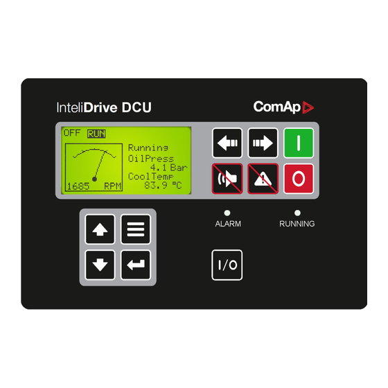
2.3 List of supported modules 6 back to Table of contents 2.1 Operator Interface Cycle forward through engine operation modes: OFF-RUN. Cycle backward through engine operation modes: OFF-RUN. Deactivates the HORN. Acknowledges faults and alarms. InteliDrive DCU Industrial 3.4.0 Global Guide... -
Page 10: Controller Screens
It causes locking of the front panel buttons during the Cooling state. 2.1.1 Controller screens There are three screen groups available on ID controller: Measuring – Setpoints – History. Measuring screen will be divided to more groups – ID-DCU Industrial, BIN/BOUT, AIN. InteliDrive DCU Industrial 3.4.0 Global Guide... - Page 11 IS-BIN BI indication 9 to 16 IS-BIN BO indication 1 to 8 ECU values I. ECU values II. Setpoints screens correspond with Setpoint table above. Alarm indication Possible Alarm list and History record prefixes InteliDrive DCU Industrial 3.4.0 Global Guide...
- Page 12 Info screen Info Comment InteliDrive Product type ComAp 2019 Company name, year of release Controller type Serial: 0200FFFF Controller serial number Sw ver: 3.4.0 Software version Appl: SS Application Branch: DCU Industrial Firmware branch InteliDrive DCU Industrial 3.4.0 Global Guide...
- Page 13 ID-DCU Industrial Battery voltage <, > Wrn SHBIN 1 to 6 Sd SHBIN 1 to 6 Wrn DISTBIN 1 to 32 Sd DISTBIN 1 to 32 Wrn SHAIN 1 to 4 Sd SHAIN 1 to 4 Wrn CommError(1) to (10) InteliDrive DCU Industrial 3.4.0 Global Guide...
- Page 14 Start from ID-DCU Industrial start RS232 control + Button Start from InteliMonitor start Remote start ID-DCU Industrial binary input RemRepStart ID-DCU Industrial binary input Blackout start ID-DCU Industrial binary input Button start ID-DCU Industrial panel button InteliDrive DCU Industrial 3.4.0 Global Guide...
- Page 15 Controller was switched on Cfg loaded Configuration archive was changed FwLoaded Firmware upgrade Time stamp Depends on setpoint setting period Password set Any level from any terminal Password changed Any level from any terminal InteliDrive DCU Industrial 3.4.0 Global Guide...
-
Page 16: Display Menu
2.1.2 Display menu There are 4 display menus available: MEASUREMENT, External measurement, ADJUSTMENT and HISTORY. Each menu consists of several screens. Pressing the Page button repeatedly will scroll the user through the menu screens. InteliDrive DCU Industrial 3.4.0 Global Guide... -
Page 17: Functions Available From Id-Dcu Industrial Front Panel Keys
ID-DCU Industrial screen. Press Page to return back to Language selection. Note: The Fast Edit function is available only in case of accessible parameter, i.e. if entered password level on ID-DCU Industrial corresponds to protected level of parameter associated to Fast Edit function. InteliDrive DCU Industrial 3.4.0 Global Guide... -
Page 18: How To Change Controller Language
2.1.9 How to select engine mode? Use Mode → or Mode ← to select requested engine operation mode. Note: Switching to OFF mode is blocked on running engine as well as the automatic switching prior to controller programming. InteliDrive DCU Industrial 3.4.0 Global Guide... -
Page 19: How To View And Edit Setpoints
2. Use ↑ or ↓ to select a requested record. 3. Use Enter to select requested screen (record items) within displayed records 2.1.13 Main screen indication Active controller mode (inverse) Available mode Controller LOC (Local) mode indication InteliDrive DCU Industrial 3.4.0 Global Guide... -
Page 20: Controller Configuration And Monitoring
RPM indication 2.2 Controller configuration and monitoring InteliDrive Install Suite is pack contains separate PC software tools related to ComAp products. The main components are: DriveConfig (DC), InteliMonitor (IMON) and InteliDDE server. DriveConfig and InteliMonitor is based on Windows Vista/Win7/Win8 or higher platform. -
Page 21: Configuration Steps
PTC protection activates and interrupts RS232 communication. In such case disconnect RS232 line wait a minute for PTC recovery and try again. The simple solution is to assure, that the PC supply 240/20V is ground free (GND terminal is not connected). InteliDrive DCU Industrial 3.4.0 Global Guide... -
Page 22: Driveconfig
Complete I/O configuration (include extension modules if any) Setpoints setting All available languages Configuration file can be opened (Open file or Load from ID) modified and stored to the PC (Save, Save as) or downloaded to Controller (Store to ID). InteliDrive DCU Industrial 3.4.0 Global Guide... -
Page 23: Modbus Protocol
16-bit communication object number. The register, according to Modbus communication protocol, represents a two-byte data and in communication functions is referenced by 16-bit register address. Further in the description InteliDrive DCU Industrial 3.4.0 Global Guide... -
Page 24: Password Protection
Setting of statistic is possible protect separately - from Monitor only 2.2.7 WebSupervisor WebSupervisor is web based system designed for monitoring and controlling ComAp controllers via the Internet. This system offers a number of beneficial features that help optimize revenue for machinery fleets, as each piece of equipment can be individually monitored for all important operation values. -
Page 25: List Of Supported Modules
2. Internet connection without AirGate – using InteliBridge-NT (IB-NT) or IG-IB module. The module has to have fixed and public IP address. Note: The WebSupervisor ComAp tool is supported from ID-DCU Industrial version 3.1, specifically from ID- DCU-INDUSTRIAL-W-3.1.mhx firmware. 2.3 List of supported modules... - Page 26 Internet bridge IB-NT Communication I-CB I-CB bridge I-AOUT8 8 Analog outputs I-AOUT8 You can get more information on wiring of standard extension modules in the chapter Extensional modules (page 282). 6 back to System overview InteliDrive DCU Industrial 3.4.0 Global Guide...
-
Page 27: Application Overview
OFF mode All ID-DCU Industrial controller is switched off. Engine can’t be started or running engine is stopped, prelubrication function is not active. Firmware and controller configuration can be changed in OFF mode only. InteliDrive DCU Industrial 3.4.0 Global Guide... -
Page 28: Universal States
Analog input). This way can be configured protection to any ID-DCU Industrial internal value or more levels external indication. Example of Universal state1 configuration to Engine speed (Warning for Engine speed > 1600RPM, 1s): This configuration is available in DriveConfig – Expert mode. InteliDrive DCU Industrial 3.4.0 Global Guide... - Page 29 InteliDrive DCU Industrial 3.4.0 Global Guide...
-
Page 30: Installation And Wiring
Active alarm indication alarm is still active. Disappears after "Fault reset" c onfirmation.- when alarm is inactive. Right GREEN Engine running indication Light when engine is running. Note: Please check the last software version. InteliDrive DCU Industrial 3.4.0 Global Guide... -
Page 31: Communication Lines Wiring
(e.g. Start, Stop commands) and analog outputs (e.g. Speed request). ECU size (count of input and output resources) are configurable and depends on controller possibilities. 4.1.4 ID-DCU Industrial dimensions ID-COM and ID-SCM (ID-SCM1) are mounted directly to ID-DCU Industrial case. InteliDrive DCU Industrial 3.4.0 Global Guide... -
Page 32: Id-Com Terminals
The new standard ID-COM will only be with the RS485 interface. Note: Maximal torque to tight main screw is 0.25 Nm. CAN1 Extension modules: EMS, IS-AIN8(TC), IS-BIN16/8, IGS-PTM, IGL-RA15 CAN2 Intercontroller: I-LB+, IG-IB, IB-NT, others ID-DCU Industrial InteliDrive DCU Industrial 3.4.0 Global Guide... - Page 33 Note: Put jumper to connect the internal 120 Ω terminating resistor for CAN2 interface. ID-COM module is not required when inter-controller CAN2 line is not used. In this case connect Extension modules CAN1 directly to Extension modules port ID-COM on ID-DCU Industrial (9-pin connector: 5=H, 9=L). InteliDrive DCU Industrial 3.4.0 Global Guide...
-
Page 34: Id-Dcu Industrial Terminals
4.1.7 ID-DCU xx -LT version with display preheating LT is an option for extending of operating temperature range from -20 to -40 °C. Heating foil is not part of standard ID-DCU and ID-MCU (without -LT extension). InteliDrive DCU Industrial 3.4.0 Global Guide... -
Page 35: Id-Scm Speed Control Module
(active) impulse sensor with maximal frequency range up to 60 Hz. Minimal pulse duration is 1ms. The output values SCM Imp1, SCM Imp2 calculation use setpoints SCM unit: TransferRate1 and TransferRate2 - see below. ID-SCM inputs wiring example Magnetic pickup wiring to RPM1 and RPM2 inputs. InteliDrive DCU Industrial 3.4.0 Global Guide... -
Page 36: Id-Scm1
Number of analog outputs: 1, no galvanic separation Analog output refreshment: 100 ms Analog output options PWM 1600 Hz (fix), 5V level, max 10 mA 0 to 10VDC ± 1%, 10 kΩ output resistance InteliDrive DCU Industrial 3.4.0 Global Guide... -
Page 37: Intelivision 5 Can, Intelivision 5 Can Backlit
10 corresponding terminal female pins ECU Simulator set containing supported USB/CAN converter and various cabling, for new firmware / font / logo download into the InteliVision 5 CAN InteliDrive DCU Industrial 3.4.0 Global Guide... - Page 38 Power supply 8 – 36VDC 6 - 8 CAN bus (with galvanic separation) Binary output configured for Horn function. It is Solid State Relay with galvanic separation. Max 3 - 4 36VDC/0,5A (like free contact). InteliDrive DCU Industrial 3.4.0 Global Guide...
-
Page 39: Intelivision 8, Intelivision 8 Marine
Note: It is possible to connect up to five InteliVision 5 CAN or four InteliVision 8 displays to common CAN2 bus. The display addresses must be different in this case. 4.1.11 InteliVision 8, InteliVision 8 Marine InteliDrive DCU Industrial 3.4.0 Global Guide... -
Page 40: Intelivision 12Touch And Intelivision 12Touch Oem
4.1.12 InteliVision 12Touch and InteliVision 12Touch OEM InteliVision 12Touch, industrial operator panel equipped with a 12,1” colour, multi-touch screen, is dedicated together with the main ComAp controller to visualize and control single gen-set and drive controllers in various applications. It is designed as an intuitive, easy to use Plug and Play solution and delivers high visibility of all engine data, monitoring information and trend history in a bright, colorful and impressive industrial capacitive touch based design. - Page 41 Image 4.2 InteliVision 12Touch – dimensions Image 4.3 Wiring example: ID-DCU Industrial to InteliVision 12Touch Note: For more information see InteliVision 12Touch OEM Global Guide. InteliDrive DCU Industrial 3.4.0 Global Guide...
-
Page 42: Recommended Wiring
Maximal CAN2 bus length is up to 200 meters when Basic settings: CAN bus mode = 250 kBd or up to 900 meters when Basic settings: CAN bus mode = 50 kBd. For CAN data cables details see chapter Technical data – Communication interface. CAN cable shielding connect to ID-DCU Industrial case. InteliDrive DCU Industrial 3.4.0 Global Guide... -
Page 43: Electronic Engine Without Redundancy Line
IGS-PTM unit contains internal jumper-removable 120 Ω resistor. To be sure check resistor presence by ohmmeter. Unit with internal resistor should be connected to the end of CAN2 line. 4.2.2 Electronic engine without redundancy line InteliDrive DCU Industrial 3.4.0 Global Guide... -
Page 44: Engine Without Ecu (Mechanical Engine)
2. Configure corresponding CONTROLLER CAN addresses in PC configuration tool. 3. Configure separate inputs and outputs in corresponding Analog, Binary inputs, outputs in PC configuration tool. Note: In case of CAT engines, there is RS232 connection between I-CB and CCM. InteliDrive DCU Industrial 3.4.0 Global Guide... -
Page 45: Wiring Example - Complete System Without Rpu
Do not connect binary outputs directly to DC relays without protection diodes. Use protection diodes even if the relays are not connected directly to controller outputs. Use a fast recovery 3A / 50V diodes. Image 4.4 Example of controller protection InteliDrive DCU Industrial 3.4.0 Global Guide... - Page 46 General To ensure proper function: Use grounding terminals. The InteliDrive DCU Industrial power feeding input is galvanically isolated from controller body, use the grounding terminal for proper grounding. Wiring for binary inputs and analog inputs must not be lead parallel with high voltage/current cables.
- Page 47 Power supply Use min. power supply cable of 1.5 mm2 to ensure proper function. Maximum continuous DC power supply voltage is 36VDC. Maximum allowable power supply voltage is 39VDC – see chapter Technical data. InteliDrive DCU Industrial 3.4.0 Global Guide...
-
Page 48: Analog As Binary Input
Note: The InteliDrive DCU Industrial controller should be grounded properly in order to protect against atmospheric discharges! Install separate conductors for signal and power inputs. Allow for conductor voltage drop when determining conductor size. All power supplies must have common ground. -
Page 49: Analog Sensors Availability With Extension Modules
PT1000 [°C] NI100 [°C] NI1000 [°C] Thermocpl J [°C] Thermocpl K [°C] Thermocpl L [°C] 4-20 mA passive 4-20 mA active 0-20 mA passive ±20 mA active 0-250 Ω 0-2400 Ω 0-2.4 V ±1 V InteliDrive DCU Industrial 3.4.0 Global Guide... -
Page 50: Binary Inputs/Outputs On Id-Dcu Industrial
(= without "CU" on the beginning of the name of the user curve range). 4.3.6 Binary inputs/outputs on ID-DCU Industrial Use wiring cables min. of 1.0 mm2 to ensure proper function. InteliDrive DCU Industrial 3.4.0 Global Guide... -
Page 51: Binary Output Separation
Binary output LED indication. In the Example below when EMERGENCY STOP contact is opened, the BO3 LED should light (without separating diode SD3) even if the BO3 output is opened. InteliDrive DCU Industrial 3.4.0 Global Guide... -
Page 52: Connection Of Id-Dcu Industrial Analog Inputs
ID minus Power supply terminal. To ensure a proper function use shielded cables, especially for length over >3 m. 4.3.9 ID-DCU Industrial Analog inputs hardware configuration Configure Analog inputs AI1-AI8 connection by jumpers on PCB (remove cover). InteliDrive DCU Industrial 3.4.0 Global Guide... - Page 53 - Jumper on pins 2-3. Resistance measurement - Jumper on pins 3-4. Note: Maximal voltage on controller Differential analog inputs AI5 to AI8 is in the range –2 to +5 VDC against minus power supply terminal! InteliDrive DCU Industrial 3.4.0 Global Guide...
-
Page 54: Id-Dcu Industrial Analog Inputs Software Configuration
Protections (page 64) Configure protection activity: All the time or Engine running with three different adjustable Block type delays when protectioln is active after engine start (RPM > Starting RPM). Bargraph Bargraph starting value. InteliDrive DCU Industrial 3.4.0 Global Guide... - Page 55 For 1V or 100mV Voltage: 2-3 Tristate Resistance: 3-4 0 to 5 VDC Adjustable Voltage: 2-3 Configuration examples Conversion from 4-20 mA to 6.0 Bar Oil pressure sensor (Wrn+Sd protection and Oil press function) InteliDrive DCU Industrial 3.4.0 Global Guide...
- Page 56 HW configuration: CU 0-1 V can be used for characteristics ±1 V, but this ± characteristics can be configured to AI5 to AI8 inputs only! Sensor range (gray background) automatically follows the User sensor characteristics (zero value at the above picture is not important). Conversion from ±20 mA to ±100 % request InteliDrive DCU Industrial 3.4.0 Global Guide...
- Page 57 1. Create User sensor as below. 2. Configure user sensor instead default ± 20mA sensor. 3. Configure Bargraph 100% to correspond User sensor. Bargraph indicates full 0 to 100% range in this case. 1. Create sensor like below. InteliDrive DCU Industrial 3.4.0 Global Guide...
- Page 58 2. Configure user sensor instead default ± 20mA sensor. User sensor examples Availability Configuration 0 - 20mA / 600 AI1 to AI4 AI5 to AI8 Analog input jumper = 1-2 (current) 4 - 20mA / 100,0 AI1 to AI4 AI5 to AI8 InteliDrive DCU Industrial 3.4.0 Global Guide...
-
Page 59: Analog Outputs Software Configuration
It is possible to set up to 30 points non-linear sensor characteristics. Connect external resistors (voltage divider) to extend input voltage range. 4.3.11 Analog outputs software configuration Configuration Image 4.5 Unconfigured analog output properties InteliDrive DCU Industrial 3.4.0 Global Guide... - Page 60 0-10000, both on input and output. Without conversion, the physical output value is used as in the Output conversion limits table. Image 4.6 Analog output limits calculator For physical outputs, the calculator provides help in the form of automatic recalculation to the resultant voltage/current/percentage. InteliDrive DCU Industrial 3.4.0 Global Guide...
- Page 61 Image 4.7 Active conversion of the input variable to the output value of the physical output Conversion Speed request (0-100,0%) to PWM output (0-100,00%) Image 4.8 Active conversion of the input variable working with decimal point InteliDrive DCU Industrial 3.4.0 Global Guide...
- Page 62 Normalization output saves us the work of adaptation values, otherwise we would have to use PLC and number converted to the expected number of decimal places. Image 4.10 Normalization internal integer variable to target output value InteliDrive DCU Industrial 3.4.0 Global Guide...
-
Page 63: Controller Setup
Starting - RPM is higher, than starting RPM. Engine usually keeps on increasing the RPM. Running Loaded - Engine is connected to load. Unloading - Unloading process after the stop request is received by the controller. InteliDrive DCU Industrial 3.4.0 Global Guide... -
Page 64: Protections
5.1.3 Protections Brief description of the controller's protection - basic settings and use cases. Note: There are visible only the first two bar graph marks for protection limits indication on ID-DCU Industrial screen !!! InteliDrive DCU Industrial 3.4.0 Global Guide... - Page 65 How to configure analog input window protection 1. Switch DriveConfig to EXPERT mode. 2. Configure standard two level analog protection InteliDrive DCU Industrial 3.4.0 Global Guide...
- Page 66 Protection is announced when it gets over the limit Level 1 (and Level 2) Limit Setpoint:Value. The delay of Delay Setpoint:Value can be applied to the protection. Alarm notification in the alarm list and in history Sensor defect when receiving invalid or no value, announces the Fls Analog input name InteliDrive DCU Industrial 3.4.0 Global Guide...
- Page 67 ECU is not communicating when evaluation of ECU communication failure is blocked ECU Power Relay (in logical 0) block CommFail alarm and related alarms ECUComFailBlck (in logical 1) block only CommFail alarm, FLS alarm will be announced! InteliDrive DCU Industrial 3.4.0 Global Guide...
- Page 68 When Logical Analog Input Requested RPM indicates sensor fail or it is not configured and Binary input Back Up Speed is closed the Loadsharing: ThrottlePos value is adjusted to the Loadsharing: Back Up Speed, the ThrottlePos value change is influenced by ramp Loadsharing: RQSP Ramp. InteliDrive DCU Industrial 3.4.0 Global Guide...
- Page 69 RPM (SpeedRequest% ActualSpeed% <0.5 %) or when following conditions are valid in period longer than Overload del: Example describing Overload protection activation, i.e. when the Engine speed falls down below yellow or brown limit. InteliDrive DCU Industrial 3.4.0 Global Guide...
- Page 70 Under speed protection Under speed protection is activated 5 sec after RPM > Engine params: Starting RPM. Engine underspeed is detected when RPM drops below setpoint Engine Protect: UnderSpeed. Protection delay and blocking InteliDrive DCU Industrial 3.4.0 Global Guide...
-
Page 71: Universal States
State is resetted (output is opened) when corresponding Alarm is not active and confirmed (Fault reset was pressed). There are seven universal (free) states available in ID-DCU Industrial-3.4.0 that are not joined to any value or input. InteliDrive DCU Industrial 3.4.0 Global Guide... -
Page 72: Plc - Programmable Functions
0,0 to 10,0 bars, then setpoint limit is e.g. 3,2. Any time and delay limit is in 0,1s step in the range 0,1 to 3276,7 sec. PLC consistency check indicates incorrect PLC configuration. InteliDrive DCU Industrial 3.4.0 Global Guide... -
Page 73: List Of Available Plc Functions
IMPORTANT: Logic for controlling the motor can't be locked in PLC. Certification authority can ask for access to the content locked this way. PLC Function Selection Available Number of available blocks in ID-DCU Industrial 3.4.0 OR/AND 128x XOR/RS 128x Comp Hyst Comp Time InteliDrive DCU Industrial 3.4.0 Global Guide... - Page 74 PLC Function Selection Available Number of available blocks in ID-DCU Industrial 3.4.0 Comp Win. Math Fc Ext Math Fc Interpol Fc 'B' Nonlin I Fc Math AxB/C PID Bin InteliDrive DCU Industrial 3.4.0 Global Guide...
- Page 75 PLC Function Selection Available Number of available blocks in ID-DCU Industrial 3.4.0 PID Ana C Ramp Up/Down Inc/Dec Mov Avg Timer Delay Delay B InteliDrive DCU Industrial 3.4.0 Global Guide...
-
Page 76: Plc Configuration Example
Mux Const. Counter Decomp Convert 3D Map 5.2.3 PLC configuration example Let suppose a diesel compressor. The engine speed is controlled via ID-SCM Speed governor analog output (no data communication). InteliDrive measures output pressure. InteliDrive DCU Industrial 3.4.0 Global Guide... - Page 77 Based on adjustable pressure limits ID controller switch the engine between RPM1 to RPM2. When Pressure drops below Pressure ON limit engine increases from RPM1 to RPM2 and after Pressure increases above Press OFF limit goes back to RPM1. Function structure InteliDrive DCU Industrial 3.4.0 Global Guide...
- Page 78 Industrial Analog input 4. Wrn and Sd protection limits should be adjusted over Pressure OFF limit. 3. Go to PLC window and drag & drop PLC functional block Comp Hyst, double click the block. 4. Configure Comparator Input: click on button and select input value from the list. InteliDrive DCU Industrial 3.4.0 Global Guide...
- Page 79 6. Edit setpoint name in PLC setpoints list. Result look like this 7. Drag & drop PLC functional block Ana Switch, configure Input 1 and Input 2 as PLC setpoints and edit the setpoint names to RPM 1 and RPM 2. InteliDrive DCU Industrial 3.4.0 Global Guide...
- Page 80 10. Go to I/O window and configure analog SCM AOUT1 as RPM out. Then configure output convert Low limit (0 RPM ~ 0.00V output) and High output convert limit (2000 RPM ~ 10.00V output). InteliDrive DCU Industrial 3.4.0 Global Guide...
- Page 81 From DriveConfigversion 3.8.0 it is possible to lock PLC Sheets individually in the controllers supporting this feature. Available are 3 passwords, user can assign one of them to each PLC sheet or leave PLC sheet unlocked. InteliDrive DCU Industrial 3.4.0 Global Guide...
- Page 82 If password is used for any PLC sheet, password will be removed from appropriate PLC sheets (user has to confirm this). Correct password must be entered. If password is not used for any PLC sheet, password is removed immediately without warning. No need to enter correct password. InteliDrive DCU Industrial 3.4.0 Global Guide...
-
Page 83: Shared Io And Virtual Io
PLC module input. Therefore it is necessary to use VBOUT module as interface between a Prg. state signal and a PLC module. Up to 4 VBOUT modules are available, each VBOUT modules represents 8 binary output signals. InteliDrive DCU Industrial 3.4.0 Global Guide... -
Page 84: Shared Virtual Inputs And Outputs
IMPORTANT: For proper function of Shared Binary and Analog Inputs and Outputs, only one source of Shared Binary or Analog Outputs must be configured (i.e. it is not possible to configure in one controller SHBOUT1 and to another one as well SHBOUT1). InteliDrive DCU Industrial 3.4.0 Global Guide... -
Page 85: Distributed Binary Inputs And Outputs
(meaning that the controller will be receiving all DISTBOUT from all the controller, even his own). It is not possible to change the name of DISTBIN inputs or add protections. In the example below you can see 4 controllers with various DISTBIN and DISTBOUT configuration. InteliDrive DCU Industrial 3.4.0 Global Guide... -
Page 86: Multiple Ecu Modules Support
Use Modules card in DriveConfig to configure support of ECU modules with the Insert/Remove buttons: IMPORTANT: Be aware that it is necessary to use ECU list, which enables use of multiple ECU modules. Check and select used ECU list using this option: InteliDrive DCU Industrial 3.4.0 Global Guide... - Page 87 It is recommended to use this option and use different setting only if the default one does not work. Example: Set Module address to 5, if engine CAN1 address is 5. InteliDrive DCU Industrial 3.4.0 Global Guide...
- Page 88 Analog inputs (4B) – Number of 4B analog input values available with module. Note: Total number of available 4B analog input values is limited to 20 with all configured modules (e.g. 5 modules with 4 inputs would use all available inputs). 6 back to Controller setup InteliDrive DCU Industrial 3.4.0 Global Guide...
-
Page 89: Communication
Tier 4 Final/StageV support generally provides monitoring and control of after-treatment system installed on generators engine. The requirements are defined as: Providing After-Treatment status information by displaying universal lamps (icons) displaying analog and binary values InteliDrive DCU Industrial 3.4.0 Global Guide... - Page 90 Image 6.2 Example of inactive Tier 4 Final/StageV screen Universal lamps (icons) Universal lamp icons are shown on the After-Treatment screen. Based on specific value read in specific frame with specific SPN is every lamp icon either: InteliDrive DCU Industrial 3.4.0 Global Guide...
- Page 91 Note: DPF = Diesel Particulate Filter; SCR = Selective Catalytic DPF/SCR lamp command Reduction. This lamp also activates alarm After- treatment Note: This lamp also Exhaust system high temperature activates alarm After- lamp command treatment InteliDrive DCU Industrial 3.4.0 Global Guide...
- Page 92 Fluid tank low level indicator activates alarm After- treatment Note: Indicates the state of diesel particulate filter active regeneration DPF regeneration inhibited inhibition. This lamp also activates alarm After- treatment 6 back to Communication InteliDrive DCU Industrial 3.4.0 Global Guide...
-
Page 93: Technical Data
5 – 25 Hz, ±1.6mm Vibration 25 – 100 Hz, a = 4 g Shocks a = 200 m/s2 Heat radiation Dimensions and weight (183×123×47 mm) Dimensions See chapter terminals and dimensions Weight 800 g InteliDrive DCU Industrial 3.4.0 Global Guide... - Page 94 Maximal current range 0 – 20 mA Input impedance 180 Ω for mA measuring Input impedance >100 kΩ for V measuring Resistance measurement tolerance ± 2 % ± 2 Ω out of measured value InteliDrive DCU Industrial 3.4.0 Global Guide...
-
Page 95: Can Bus Interface
Following dynamic cable parameters are important especially for maximal 200 meters CAN bus length and 32 ID-COM units connected: Nominal Velocity of Propagation min. 75 % (max. 4.4 ns/m) Wire crosscut min. 0.25 mm Maximal attenuation (at 1 MHz) 2 dB / 100 m InteliDrive DCU Industrial 3.4.0 Global Guide... - Page 96 3085A DeviceBus for Allen-Bradley DeviceNet 3105A Paired EIA Industrial RS485 cable LAPP CABLE (see http://www.lappcable.com) Unitronic BUS DeviceNet Trunk Cable Unitronic BUS DeviceNet Drop Cable Unitronic BUS CAN Unitronic-FD BUS P CAN UL/CSA 6 back to Technical data InteliDrive DCU Industrial 3.4.0 Global Guide...
-
Page 97: Appendix
8 Appendix 6 back to Table of contents InteliDrive DCU Industrial 3.4.0 Global Guide... -
Page 98: Controller Objects
Engine protect RPMdep protect (AS only) Load sharing Analog inputs Date and Time ID-SCM unit Protections For full list of setpoints go to the chapter List of setpoints (page 99) 6 back to Controller objects InteliDrive DCU Industrial 3.4.0 Global Guide... - Page 99 RS232 Mode OPNomRPMSd BinInp Delay 1 RS232 TermCSpd OilPrRPMdel BinInp Delay 2 RS485 MBCSpd CPIdleRPMWrn BinInp Delay 3 RS485 Mode CPNomRPMWrn ForceBlockDel1 RS485 TermCSpd CPIdleRPMSd ForceBlockDel2 SHxOcol Detect CPNomRPMSd ForceBlockDel3 CoolPrRPMdel Overspeed UnderSpeed MinLoadSpeed InteliDrive DCU Industrial 3.4.0 Global Guide...
- Page 100 Group of setpoints: Date/Time Time Date Time Stamp Per SummerTimeMod EnTimeSync Group of setpoints: ID- SCM unit FreqRate1 FreqRate2 TransferRate1 TransferRate2 Group of setpoints: DetCon20 IgnRedLimit ImmStopLimit DecreaseRamp TimingRedGain DelayLoadRed 6 back to Controller objects InteliDrive DCU Industrial 3.4.0 Global Guide...
- Page 101 Has to be set before remote modem or SMS connection is opened. Can be up to 16 ASCII characters At first Password 3 has to be entered before the new Access code can be changed. InteliDrive DCU Industrial 3.4.0 Global Guide...
- Page 102 InteliVision 8 (Marine) – depends on screen configuration in archive of ID-DCU Industrial controller. Default archives for ID-DCU Industrial version 2.1 and higher support independent password protection of Stop command according to description above. Note: All setpoints below can be modified from Remote panel or InteliMonitor as well. InteliDrive DCU Industrial 3.4.0 Global Guide...
- Page 103 8252 Related applications AS, SS Description Number of teeth on the engines flywheel for the pick-up. Setpoint (RPM pickup measuring) is ignored when RPM is received via J1939. 6 back to List of setpoints InteliDrive DCU Industrial 3.4.0 Global Guide...
- Page 104 Alarm list indication ECU Diag disabled is indicated when ECU diagnostics is disabled. The ECU Diagnostic is controlled by ECU DiagBlck binary input in case of setting to EXTERNAL. 6 back to List of setpoints InteliDrive DCU Industrial 3.4.0 Global Guide...
- Page 105 Activates/deactivates the logical binary output Nominal Sw, that can be configured as J1939 output to switch ECU. BIN.INPUT: IDLE/NOMINAL mode is switched via BI I 180) (NOMINAL when closed). PAGE 6 back to List of setpoints InteliDrive DCU Industrial 3.4.0 Global Guide...
- Page 106 In case no ECU support is configured, internal running hours value is used despite RunHoursSource setting. 6 back to List of setpoints InteliDrive DCU Industrial 3.4.0 Global Guide...
- Page 107 Basic settings Related FW 3.4.0 Range [units] [hh:mm:ss] Force value Default value 0:00:00 Alternative config Step Comm object 10042 Related applications AS, SS Description Timer Repeat (page 108) description. 6 back to List of setpoints InteliDrive DCU Industrial 3.4.0 Global Guide...
- Page 108 Timer OFF. The function depends on Timer Repeat settings. The output is closed when controller is switched On and Timer settings corresponds to closed state. 6 back to List of setpoints InteliDrive DCU Industrial 3.4.0 Global Guide...
- Page 109 Other units IG-IB, IB-NT detect CAN bus speed automatically. Note: If the controller is connected to IB-NT, set the mode to 8C - verified stable communication speed. 6 back to List of setpoints InteliDrive DCU Industrial 3.4.0 Global Guide...
- Page 110 Message ECU Diag disabled is displayed in the alarm list while ECU diagnostics is disabled. The ECU Diagnostic is disabled/enabled using LBI:ECU DiagBlck binary input in case of setting to EXTERNAL. 6 back to List of setpoints InteliDrive DCU Industrial 3.4.0 Global Guide...
- Page 111 Alternative config Step Comm object 24477 Related applications AS, SS Description The setpoint adjusts communication speed of the RS232 interface when RS232 Mode (page 112) is set to Modbus. 6 back to List of setpoints InteliDrive DCU Industrial 3.4.0 Global Guide...
- Page 112 RS232 Mode (page 112) is set to STANDARD. Note: If the controller is connected to IB-NT via the RS232 interface, set the speed to 57600 - the supported communication speed. 6 back to List of setpoints InteliDrive DCU Industrial 3.4.0 Global Guide...
- Page 113 ECU LINK: Connection to an electronic-controlled engine which uses non-J1939 ECU. The proper ECU type must be also configured with DriveConfig. Note: Detailed description of Modbus protocol include some examples, see in InteliDrive Communication guide. 6 back to List of setpoints InteliDrive DCU Industrial 3.4.0 Global Guide...
- Page 114 Normally a collision would be indicated if there were more sources on the bus and this setpoint can be used to disable the evaluation of collisions in this special case. 6 back to List of setpoints InteliDrive DCU Industrial 3.4.0 Global Guide...
- Page 115 Comm object 9095 Related applications AS, SS Description “Firing” speed when controller stops cranking = one of the engine running indications. Note: Under speed limit is fix 30 RPM. 6 back to List of setpoints InteliDrive DCU Industrial 3.4.0 Global Guide...
- Page 116 Coolant pressure limit = one of the engine running indications. To activate this function any Analog input must be configured to Analog logical input Coolant press. Note: PRP only Note: Step, Range and dimension depend on corresponding Analog input sensor characteristic. 6 back to List of setpoints InteliDrive DCU Industrial 3.4.0 Global Guide...
- Page 117 CMB, EME: 3 ..200 [s], AUX, PRP: 0 .. 200 [-] Force value Default value Alternative config Step Comm object 8257 Related applications AS, SS Description Pause between cranking attempts. 6 back to List of setpoints InteliDrive DCU Industrial 3.4.0 Global Guide...
- Page 118 Force value Default value Alternative config Step Comm object 9946 Related applications AS Description Default Idle speed (should be the same as Idle speed set with engine ECU). 6 back to List of setpoints InteliDrive DCU Industrial 3.4.0 Global Guide...
- Page 119 Prelubrication for this amount of time, then pause for PrelubrPause, then activate again. This will continue the entire time the engine is not running. Function is not active in controller OFF mode. 6 back to List of setpoints InteliDrive DCU Industrial 3.4.0 Global Guide...
- Page 120 0 .. 600 [s] Force value Default value Alternative config Step Comm object 8258 Related applications AS, SS Description Runtime of unloaded engine to cool down engine before stopping. 6 back to List of setpoints InteliDrive DCU Industrial 3.4.0 Global Guide...
- Page 121 CHRGFAIL: The D+ terminal is used for charge fail detection only DISABLED: The D+ terminal is not used. Note: Alternator magnetization current is provided independently from the parameter setting. 6 back to List of setpoints InteliDrive DCU Industrial 3.4.0 Global Guide...
- Page 122 Default value Alternative config Step Comm object 9984 Related applications AS, SS Description Speed ramp setting for 179) 178), not for Analog input request. PEED PAGE PEED PAGE 6 back to List of setpoints InteliDrive DCU Industrial 3.4.0 Global Guide...
- Page 123 Fast edit function: press Enter for 4 sec, / ¯ set value, press Enter to confirm, see Speed Request (page 256) charts for PRP and AUX / EME / HRB modes. 6 back to List of setpoints InteliDrive DCU Industrial 3.4.0 Global Guide...
- Page 124 #2) are started to be evaluated. The "running only" alarms are not beeing evaluated while the engine is not running or then, after start, while the adjusted delay is running. For details see drawing, which is part of RunOnlyBlkDel3 (page 125) description. 6 back to List of setpoints InteliDrive DCU Industrial 3.4.0 Global Guide...
- Page 125 Starting POil (page 116) Analog input Coolant Press > StartPCoolant (page 116) (PRP only) or Active Binary input RunIndication1 or Active Binary input RunIndication2 or Active Binary input RunIndication3. 6 back to List of setpoints InteliDrive DCU Industrial 3.4.0 Global Guide...
- Page 126 Binary input protection is activated when input is closed for longer time than BinInp delay 2. To use this filter, binary input protection Delay must be configured in DriveConfig to BinInp delay 2. For details see BinInp Delay 3 (page 127) description. 6 back to List of setpoints InteliDrive DCU Industrial 3.4.0 Global Guide...
- Page 127 BinInp delay x is active only for Binary inputs configured as protection and it is related to protection only. BinInp delay x does not affect optional logical function of an input. 6 back to List of setpoints InteliDrive DCU Industrial 3.4.0 Global Guide...
- Page 128 Delay for Force block protection activation after binary input Force Block 2 is opened. Protection deactivation is without delay. Protection is activated/deactivated independent on engine running or not running state. 6 back to List of setpoints InteliDrive DCU Industrial 3.4.0 Global Guide...
- Page 129 Default value Alternative config Step Comm object 8260 Related applications AS, SS Description Underspeed alarm is activated when engine is running and actual RPM is below the UnderSpeed threshold. 6 back to List of setpoints InteliDrive DCU Industrial 3.4.0 Global Guide...
- Page 130 Range [units] 8.0 .. Batt >V [V] Force value Default value Alternative config Step Comm object 8387 Related applications AS, SS Description Warning level for low battery voltage. 6 back to List of setpoints InteliDrive DCU Industrial 3.4.0 Global Guide...
- Page 131 Related FW 3.4.0 Range [units] 0 .. 600 [s] Force value Default value Alternative config Step Comm object 9947 Related applications Description Delay for Overload RPM protection limit. 6 back to List of setpoints InteliDrive DCU Industrial 3.4.0 Global Guide...
- Page 132 194) is activated , if ECU alarm is received by controller. OMMON PAGE ALARM ONLY: 194) is not activated, if ECU alarm is received by controller. OMMON PAGE 6 back to List of setpoints InteliDrive DCU Industrial 3.4.0 Global Guide...
- Page 133 AS Description Linear Warning characteristic is defined by two points for Idle RPM (page 118) Nominal RPM (page 104). OPIdleRPMWrn defines oil pressure warning level at idle speed. 6 back to List of setpoints InteliDrive DCU Industrial 3.4.0 Global Guide...
- Page 134 Linear Shutdown characteristic is defined by two points for Idle RPM (page 118) Nominal RPM (page 104). OPNomRPMSd defines oil pressure shutdown level at nominal speed. For details see OilPrRPMdel (page 135) description. 6 back to List of setpoints InteliDrive DCU Industrial 3.4.0 Global Guide...
- Page 135 Linear Warning characteristic is defined by two points for Idle RPM (page 118) Nominal RPM (page 104). CPIdleRPMWrn defines coolant pressure warning level at idle speed. For details see CoolPrRPMdel (page 137) description. 6 back to List of setpoints InteliDrive DCU Industrial 3.4.0 Global Guide...
- Page 136 Linear Shutdown characteristic is defined by two points for Idle RPM (page 118) Nominal RPM (page 104). CPNomRPMSd defines coolant pressure shutdown level at nominal speed. For details see CoolPrRPMdel (page 137) description. 6 back to List of setpoints InteliDrive DCU Industrial 3.4.0 Global Guide...
- Page 137 To activate RPM dependent coolant pressure protection any analog value has to be linked with OOLANT 235). RESS PAGE Note: RPM dependent coolant pressure protection is fix configured Protection block type = Engine running only with RunOnlyBlkDel1 delay. 6 back to List of setpoints InteliDrive DCU Industrial 3.4.0 Global Guide...
- Page 138 Force value Default value Alternative config Step Comm object 9949 Related applications AS Description Time between the clutch is switched on/off and the load sharing function is activated. 6 back to List of setpoints InteliDrive DCU Industrial 3.4.0 Global Guide...
- Page 139 Clutch can be switched on if ClutchMinSpeed < RPM < ClutchMaxSpeed. Limits are in % of Requested speed. See Function description details (page 63). Note: 0.0 % corresponds to (Idle speed + Idle offset) value, 100.0 % corresponds to Nominal speed. 6 back to List of setpoints InteliDrive DCU Industrial 3.4.0 Global Guide...
- Page 140 (page 256) in loadsharing state, if 173) is active and RPM ( 236) PEED PAGE EQUESTED PAGE reading via analog input is out of range (sensor fail is detected). 6 back to List of setpoints InteliDrive DCU Industrial 3.4.0 Global Guide...
- Page 141 Description Engine clutch start protection. Start fail alarm is activated, if engine running condition is not detected during MaxClStrPer delay time after 196) is closed. LUTCH ONNECT PAGE 6 back to List of setpoints InteliDrive DCU Industrial 3.4.0 Global Guide...
- Page 142 Description Average value calculated from all Speed Request values of controllers running in Loadsharing mode together (on the same CAN2 bus). See Load sharing block diagram (page 144). 6 back to List of setpoints InteliDrive DCU Industrial 3.4.0 Global Guide...
- Page 143 RQSP Ramp Setpoint group Load sharing Related FW 3.4.0 Range [units] 0 .. 100 [%/s] Force value Alternative Default value config Step InteliDrive DCU Industrial 3.4.0 Global Guide...
- Page 144 ThrottlePos output (request to EMS) is switched to be equal to the Speed Request (page 256) after other engines clutches are disconnected (no load sharing, only one engine powers the shaft). 6 back to List of setpoints InteliDrive DCU Industrial 3.4.0 Global Guide...
- Page 145 Range [units] -32767 .. 32767 [-] Force value Default value Alternative config Step Comm object 8467 Related applications AS, SS Description Adjustable offset for AIN3 for calibrating purposes. 6 back to List of setpoints InteliDrive DCU Industrial 3.4.0 Global Guide...
- Page 146 Range [units] -32767 .. 32767 [-] Force value Default value Alternative config Step Comm object 8795 Related applications AS, SS Description Adjustable offset for AIN6 for calibrating purposes. 6 back to List of setpoints InteliDrive DCU Industrial 3.4.0 Global Guide...
- Page 147 Range [units] -32767 .. 32767 [-] Force value Default value Alternative config Step Comm object 11599 Related applications AS, SS Description Adjustable offset for AIN8 for calibrating purposes. 6 back to List of setpoints InteliDrive DCU Industrial 3.4.0 Global Guide...
- Page 148 Alternative config Step Comm object 8485 Related applications AS, SS Description Enables or disables active calls/SMS to selected phone or mobile numbers when a Cool down alarm occurs. 6 back to List of setpoints InteliDrive DCU Industrial 3.4.0 Global Guide...
- Page 149 Note: To receive DATA active call run InteliMonitor – Type of connection = Active call. InteliMonitor Active call window contains list of received AID files. Each list item contains Engine name, Date, Time, ID serial number. 6 back to List of setpoints InteliDrive DCU Industrial 3.4.0 Global Guide...
- Page 150 Comm object 9597 Related applications AS, SS Description Address for channel 1 active call. Each above message type has either phone number or e-mail address associated with it. 6 back to List of setpoints InteliDrive DCU Industrial 3.4.0 Global Guide...
- Page 151 Comm object 9598 Related applications AS, SS Description Address for channel 2 active call. Each above message type has either phone number or e-mail address associated with it. 6 back to List of setpoints InteliDrive DCU Industrial 3.4.0 Global Guide...
- Page 152 Note: Timeout for connection is 90 sec and after 120 sec controller starts the next attempt. Incoming calls are blocked when controller is trying to send active call message. 6 back to List of setpoints InteliDrive DCU Industrial 3.4.0 Global Guide...
- Page 153 The setpoint adjusts time interval of Time stamp history records. Note: No history Time stamp is recorded when TimeStamp Per = 0. RTC and Date is in each History record. 6 back to List of setpoints InteliDrive DCU Industrial 3.4.0 Global Guide...
- Page 154 The setpoint is used to enable Time synchronization function with InteliGen-NT and InteliSys-NT controllers over CAN2 bus. The synchronization is just unidirectional from InteliGen-NT or InteliSys-NT controller into InteliDrive DCU Industrial, not vice versa. 6 back to List of setpoints InteliDrive DCU Industrial 3.4.0 Global Guide...
- Page 155 Related applications AS, SS Description Conversion ratio (number of pulses for increase by 1) for ID-SCM IMP 1 impulse input / SCM Imp1 value. Frequency range max. 60 Hz. 6 back to List of setpoints InteliDrive DCU Industrial 3.4.0 Global Guide...
- Page 156 Ignition reduction limit is knocking value above which the engine is considered to be knocking. If the value is exceeded, DetCon20 binary output ENGINE KNOCKING is activated and the values assigned to the timing reduction are altered. 6 back to List of setpoints InteliDrive DCU Industrial 3.4.0 Global Guide...
- Page 157 0.1 % Comm object 10301 Related applications AS, SS Description Timing reduction gain influences rate at which timing reduction signal (analog output) is amplified when knocking is detected. 6 back to List of setpoints InteliDrive DCU Industrial 3.4.0 Global Guide...
- Page 158 0.1 s Comm object 10303 Related applications AS, SS Description Delay after load reduction defines delay of timing signal reduction process after knocking level drops below IgnRedLimit (page 156). 6 back to List of setpoints InteliDrive DCU Industrial 3.4.0 Global Guide...
-
Page 159: Binary Inputs
BinInp delay 1, 2, 3 that can be adjusted by corresponding Setpoint BinInp Delay 1, 2, 3. Input BI delay configuration Setpoint Standard (0,5s) BinInp delay 1 BinInp Delay 1 BinInp delay 2 BinInp Delay 2 BinInp delay 3 BinInp Delay 3 See setpoints BinInp delay 1 [s] etc… InteliDrive DCU Industrial 3.4.0 Global Guide... - Page 160 RemRepStart User Mask 2 Back Up Speed1 User Mask 3 Back Up Speed2 User Mask 4 Back Up Speed3 Current Gear Fire Speed Watchdog test Rem Clutch StartBlocking1 6 back to Controller StartBlocking2 objects InteliDrive DCU Industrial 3.4.0 Global Guide...
- Page 161 InteliDrive local/remote commands blocking overview Note: Y = available, N = blocked Device Command AccessLock int AccessLock ext LOC (Local) mode ID-DCU Industrial panel START STOP FLT RES HORN Setpoint change Mode change ID-DCU Industrial Bin Inputs Remote InteliDrive DCU Industrial 3.4.0 Global Guide...
- Page 162 External modules Bin Inputs Start/Stop Remote Remote (RS232 or CAN2) STOP FLT RES HORN Setpoint change Mode change InteliMonitor START (serial line) STOP FLT RES HORN Setpoint change Mode change 6 back to List of LBI InteliDrive DCU Industrial 3.4.0 Global Guide...
- Page 163 1)) or via front panel EMOTE TART PAGE buttons. Note: When this Access Lock input is active, it is still possible to initiate programming from a remotely connected DriveConfig. 6 back to List of LBI InteliDrive DCU Industrial 3.4.0 Global Guide...
- Page 164 1)) or via front panel EMOTE TART PAGE buttons. Note: When this Access Lock input is active, it is still possible to initiate programming from a remotely connected DriveConfig. 6 back to List of LBI InteliDrive DCU Industrial 3.4.0 Global Guide...
- Page 165 1)) or via front panel EMOTE TART PAGE buttons. Note: When this Access Lock input is active, it is still possible to initiate programming from a remotely connected DriveConfig. 6 back to List of LBI InteliDrive DCU Industrial 3.4.0 Global Guide...
- Page 166 1)) or via front panel EMOTE TART PAGE buttons. Note: When this Access Lock input is active, it is still possible to initiate programming from a remotely connected DriveConfig. 6 back to List of LBI InteliDrive DCU Industrial 3.4.0 Global Guide...
- Page 167 Related FW 3.4.0 Related applications AS, SS Comm object Description Active input blocks protections that are configured as “Force Block 3” Prot. block type. Corresponding setpoint is ForceBlockDel3. 6 back to List of LBI InteliDrive DCU Industrial 3.4.0 Global Guide...
- Page 168 Remote On/Off binary input when engine LOSE PAGE RPM is over MinLoadSpeed (page 130). Remote On/Off is not active in LOC mode. 6 back to List of LBI InteliDrive DCU Industrial 3.4.0 Global Guide...
- Page 169 ECU is getting started. Also at the same time this LBI gives you flexibility to decide, when the communication alarms from ECU are relevant. Example: of PLC Editor 6 back to List of LBI InteliDrive DCU Industrial 3.4.0 Global Guide...
- Page 170 NC switch. IMPORTANT: This is a software function only. It can be extended by a "hard wired" emergency stop function, which means disconnecting power supply from the controller outputs. 6 back to List of LBI InteliDrive DCU Industrial 3.4.0 Global Guide...
- Page 171 Alarm list and History. The second edge on Binary input Remote Start skips the Idle time when engine is running in Idle state. Binary input Remote Start signal is equivalent to ID-DCU Industrial front panel Start button. 6 back to List of LBI InteliDrive DCU Industrial 3.4.0 Global Guide...
- Page 172 Active signal inhibits automatic DPF filter regeneration. 6 back to List of LBI RegenForce Related FW 3.4.0 Related applications AS, SS Comm object Description Active signal inhibits automatic DPF filter regeneration. 6 back to List of LBI InteliDrive DCU Industrial 3.4.0 Global Guide...
- Page 173 Back Up Speed1 (page 140) value. ThrottlePos (page 262) = 0.0 % when analog request is out of range and Binary input Back Up Speed is not active. 6 back to List of LBI InteliDrive DCU Industrial 3.4.0 Global Guide...
- Page 174 Comm object Description OR logical function of all StartBlocking Logical Binary inputs forces controller NotReady state ( i.e. disables engine start). It is active in LOC (Local) mode as well. 6 back to List of LBI InteliDrive DCU Industrial 3.4.0 Global Guide...
- Page 175 Load Blocking Related FW 3.4.0 Related applications AS, SS Comm object Description Active input disables the Close load function. No influence when Binary output Close load is closed. 6 back to List of LBI InteliDrive DCU Industrial 3.4.0 Global Guide...
- Page 176 Engine running state = RPM > Starting RPM (page 115) Analog input Oil pressure > Starting POil (page 116) Active Binary input RunIndication1 or Active Binary input RunIndication2 or Active Binary input RunIndication3. 6 back to List of LBI InteliDrive DCU Industrial 3.4.0 Global Guide...
- Page 177 Controller front panel engine RED LED blinks or lights Note: The setpoint Crank Attempts is not followed if Sd Override is active, crank attempts number is then unlimited in case of Blackout Start. 6 back to List of LBI InteliDrive DCU Industrial 3.4.0 Global Guide...
- Page 178 Engine speed to specific like 1500 RPM value. Note: Minimal Speed Up and Speed Down pulse duration is 110 ms to be accepted by controller. 6 back to List of LBI InteliDrive DCU Industrial 3.4.0 Global Guide...
- Page 179 Fault reset button (screen sensitive - active only in ECU Alarm list screen). Note: Activation of ECU Fault reset will affect InteliDrive DCU Industrial controller only, no reset request is sent to ECU. There is separated acknowledge input for Alarms – see Binary input AULT 168).
- Page 180 Start/Stop is still closed. To prevent unlimited number of starts – configure on 225) TART PAGE Sd protection. Note: Engine stays running when Rem Start/Stop is opened in controller LOC (Local) mode. 6 back to List of LBI InteliDrive DCU Industrial 3.4.0 Global Guide...
- Page 181 Input simulates the panel Mode → button. 6 back to List of LBI Page Button Related FW 3.4.0 Related applications AS, SS Comm object Description Input simulates the panel Page button. 6 back to List of LBI InteliDrive DCU Industrial 3.4.0 Global Guide...
- Page 182 Input controls ECU Diagnostic functionality in case of setting ECU Diag = EXTERNAL. 6 back to List of LBI Clear DayCons Related FW 3.4.0 Related applications AS, SS Comm object Description Rising edge clears Day consumption counter. 6 back to List of LBI InteliDrive DCU Industrial 3.4.0 Global Guide...
- Page 183 Related FW 3.4.0 Related applications AS, SS Comm object Description Rising edge forces to fill register Statistics: Memo2 by 241) actual value. Memo2 Statistics EMORY PAGE value can be set or resetted by InteliMonitor command. InteliDrive DCU Industrial 3.4.0 Global Guide...
- Page 184 Note: This function can be used to "swap" between two different screen instruments when certain conditions are fulfilled. Logical binary inputs Mask 1..4 can be used to define any custom condition for this "swapping" function. 6 back to List of LBI InteliDrive DCU Industrial 3.4.0 Global Guide...
- Page 185 Note: This function can be used to "swap" between two different screen instruments when certain conditions are fulfilled. Logical binary inputs Mask 1..4 can be used to define any custom condition for this "swapping" function. 6 back to List of LBI InteliDrive DCU Industrial 3.4.0 Global Guide...
- Page 186 Usually used as a source for the ECU output value. 6 back to List of LBI Binary inputs from J1939 configuration Binary inputs protection Property: Function line is free, no logical function is (usually) selected. InteliDrive DCU Industrial 3.4.0 Global Guide...
-
Page 187: Binary Outputs
Rising edge of this input will provide reset of controller processor. 6 back to List of LBI 8.1.3 Binary outputs Depending on Modules configuration there are exist more groups of binary items that can be configured to any physical binary output. InteliDrive DCU Industrial 3.4.0 Global Guide... - Page 188 Prestart ActLoadShar ECU10 Comm Fail Ready To Start AirFlaps CommError 10 Ready To Load MCU AckButton ECU11 Comm Fail RedStopLamp User Button 1 ECU12 Comm Fail Engine Running User Button 2 ECU13 Comm Fail InteliDrive DCU Industrial 3.4.0 Global Guide...
- Page 189 PLC Message 10 PLC Message 11 PLC Message 12 PLC Message 13 PLC Message 14 PLC Message 15 PLC Message 16 Emergency Stop Engine RPM Overload OthrCommEr ChrgAlternFail Stop Fail Overspeed Underspeed Pickup Fail Battery Flat InteliDrive DCU Industrial 3.4.0 Global Guide...
- Page 190 Note: When communication with any terminal is lost, the LBO: 193) is closed and a history PAGE record is written. This history record can be enabled / disabled by the setpoint LB/UART Log (page 111). 6 back to List of LBO InteliDrive DCU Industrial 3.4.0 Global Guide...
- Page 191 Note: When communication with any terminal is lost, the LBO: 193) is closed and a history PAGE record is written. This history record can be enabled / disabled by the setpoint LB/UART Log (page 111). 6 back to List of LBO InteliDrive DCU Industrial 3.4.0 Global Guide...
- Page 192 LB/UART Log (page 111). 6 back to List of LBO AmberLamp Related FW 3.4.0 Related applications AS, SS Comm object 1828 Description Indicates that engine issued a warning. 6 back to List of LBO InteliDrive DCU Industrial 3.4.0 Global Guide...
- Page 193 3.4.0 Related applications AS, SS Comm object Description The output closes if any alarm is activated and opens after Fault reset even if the Alarm is still active. 6 back to List of LBO InteliDrive DCU Industrial 3.4.0 Global Guide...
- Page 194 The output closes when any Sensor fail alarm is active. Output opens when all Fls alarms disappear and Fault reset is pressed (no Fls alarm in Alarm list). 6 back to List of LBO InteliDrive DCU Industrial 3.4.0 Global Guide...
- Page 195 6 back to List of LBO In LOC Related FW 3.4.0 Related applications AS, SS Comm object Description The output is closed, if LOC (Local) mode is selected. 6 back to List of LBO InteliDrive DCU Industrial 3.4.0 Global Guide...
- Page 196 PLC function when standard Clutch function is not used. Existing function of panel Close load button 0/1(LBO Close Load) is without change. Close Load function works for remote access from DriveMonitor, Modbus, Modem, ... as well. 6 back to List of LBO InteliDrive DCU Industrial 3.4.0 Global Guide...
- Page 197 6 back to List of LBO Starter Related FW 3.4.0 Related applications AS, SS Comm object Description Closed output energizes the engine starter. 6 back to List of LBO InteliDrive DCU Industrial 3.4.0 Global Guide...
- Page 198 6 back to List of LBO Prelubrication Related FW 3.4.0 Related applications AS, SS Comm object Description Periodic prelubrication function – see PrelubrTime (page 119) PrelubrPause (page 120). 6 back to List of LBO InteliDrive DCU Industrial 3.4.0 Global Guide...
- Page 199 6 back to List of LBO Engine Running Related FW 3.4.0 Related applications AS, SS Comm object Description It activates when RPM rises above Starting RPM (page 115) and opens when RPM=0. 6 back to List of LBO InteliDrive DCU Industrial 3.4.0 Global Guide...
- Page 200 Cooling Pump Related FW 3.4.0 Related applications AS, SS Comm object Description The output closes when engine starts and opens AfterCoolTime (page 121) delayed after stop the engine. 6 back to List of LBO InteliDrive DCU Industrial 3.4.0 Global Guide...
- Page 201 = DROOP or Governor Mode = BIN.INPUT and corresponding BI D 180) is closed. This logical output (Source) can be configured to ROOP PAGE corresponding J1939 output (e.g. Governor Mode in Volvo-IndustrialD12 Aux). 6 back to List of LBO InteliDrive DCU Industrial 3.4.0 Global Guide...
- Page 202 6 back to List of LBO Stop Pulse Related FW 3.4.0 Related applications AS, SS Comm object Description 1 sec pulse is generated in the beginning of Stop procedure. 6 back to List of LBO InteliDrive DCU Industrial 3.4.0 Global Guide...
- Page 203 Active signal indicates low level of Diesel Exhaust Fluid (DEF). It starts flashing when the DEF tank is nearly empty (e.g. when the level is 10 %), engine power may be reduced. 6 back to List of LBO InteliDrive DCU Industrial 3.4.0 Global Guide...
- Page 204 6 back to List of LBO Logical 1 Related FW 3.4.0 Related applications AS, SS Comm object Description Constant value that can be configured to any output (e.g. CurrentGear in Volvo-PRP). 6 back to List of LBO InteliDrive DCU Industrial 3.4.0 Global Guide...
- Page 205 Indicates any active protection configured as Shut down Override. 6 back to List of LBO Derating Alarm Related FW 3.4.0 Related applications AS, SS Comm object Description Power derating indication, information received from communication bus. 6 back to List of LBO InteliDrive DCU Industrial 3.4.0 Global Guide...
- Page 206 6 back to List of LBO StartButtEcho Related FW 3.4.0 Related applications AS, SS Comm object Description 1 sec pulse is generated after panel Start button is pressed. 6 back to List of LBO InteliDrive DCU Industrial 3.4.0 Global Guide...
- Page 207 6 back to List of LBO ClutchButtEcho Related FW 3.4.0 Related applications AS, SS Comm object Description 1 sec pulse is generated after panel I/0 button is pressed. 6 back to List of LBO InteliDrive DCU Industrial 3.4.0 Global Guide...
- Page 208 3.4.0 Related applications AS, SS Comm object Description AirFlaps output is activated with engine starting (when controller enters state Cranking) and it is deactivated 5 s after engine stopping. 6 back to List of LBO InteliDrive DCU Industrial 3.4.0 Global Guide...
- Page 209 InteliVision function buttons can be assigned to these LBOs User Button 1 .. 16. The configuration of button’s functionality is done via ScreenEditor feature in DriveConfig PC application. 6 back to List of LBO InteliDrive DCU Industrial 3.4.0 Global Guide...
- Page 210 InteliVision function buttons can be assigned to these LBOs User Button 1 .. 16. The configuration of button’s functionality is done via ScreenEditor feature in DriveConfig PC application. 6 back to List of LBO InteliDrive DCU Industrial 3.4.0 Global Guide...
- Page 211 InteliVision function buttons can be assigned to these LBOs User Button 1 .. 16. The configuration of button’s functionality is done via ScreenEditor feature in DriveConfig PC application. 6 back to List of LBO InteliDrive DCU Industrial 3.4.0 Global Guide...
- Page 212 6 back to List of LBO RegenForce Related FW 3.4.0 Related applications AS, SS Comm object Description Indicates that automatic DPF filter regeneration is forced using 172). EGEN ORCE PAGE 6 back to List of LBO InteliDrive DCU Industrial 3.4.0 Global Guide...
- Page 213 Comm object Description Those eight LBOs can be handled from InteliMonitor Remote switch window. This way can operator directly handle controller binary outputs or other e.g. PLC functions. 6 back to List of LBO InteliDrive DCU Industrial 3.4.0 Global Guide...
- Page 214 Comm object Description Those eight LBOs can be handled from InteliMonitor Remote switch window. This way can operator directly handle controller binary outputs or other e.g. PLC functions. 6 back to List of LBO InteliDrive DCU Industrial 3.4.0 Global Guide...
- Page 215 J1939 communication fail indication. 6 back to List of LBO ECU4 Comm Fail Related FW 3.4.0 Related applications AS, SS Comm object 2001 Description J1939 communication fail indication. 6 back to List of LBO InteliDrive DCU Industrial 3.4.0 Global Guide...
- Page 216 Description J1939 communication fail indication. 6 back to List of LBO CommError 10 Related FW 3.4.0 Related applications AS, SS Comm object 2007 Description J1939 communication fail indication. 6 back to List of LBO InteliDrive DCU Industrial 3.4.0 Global Guide...
- Page 217 J1939 communication fail indication. 6 back to List of LBO ECU16 Comm Fail Related FW 3.4.0 Related applications AS, SS Comm object 2013 Description J1939 communication fail indication. 6 back to List of LBO InteliDrive DCU Industrial 3.4.0 Global Guide...
- Page 218 6 back to List of LBO UnivState 3 Related FW 3.4.0 Related applications AS, SS Comm object Description Universal states 1 to Universal states 7 indication. See Universal states (page 28) description. 6 back to List of LBO InteliDrive DCU Industrial 3.4.0 Global Guide...
- Page 219 3.4.0 Related applications AS, SS Comm object Description The output is closed while the alarm generated by the PLC block Force Prot is present in the alarm list. 6 back to List of LBO InteliDrive DCU Industrial 3.4.0 Global Guide...
- Page 220 3.4.0 Related applications AS, SS Comm object Description The output is closed while the alarm generated by the PLC block Force Prot is present in the alarm list. 6 back to List of LBO InteliDrive DCU Industrial 3.4.0 Global Guide...
- Page 221 3.4.0 Related applications AS, SS Comm object Description The output is closed while the alarm generated by the PLC block Force Prot is present in the alarm list. 6 back to List of LBO InteliDrive DCU Industrial 3.4.0 Global Guide...
- Page 222 Engine speed state indication. Output is closed when no RPM is received from J1939 (sensor fail) or Overspeed or Under speed is detected. 6 back to List of LBO Overload Related FW 3.4.0 Related applications AS, SS Comm object Description Active overload protection activation. 6 back to List of LBO InteliDrive DCU Industrial 3.4.0 Global Guide...
- Page 223 AS, SS Comm object Description Engine overspeed indication. 6 back to List of LBO Underspeed Related FW 3.4.0 Related applications AS, SS Comm object Description Under speed indication. 6 back to List of LBO InteliDrive DCU Industrial 3.4.0 Global Guide...
- Page 224 Not Lubricated Related FW 3.4.0 Related applications AS, SS Comm object Description The lubrication cycle (PrelubrTime) is not finished after controller Switch on or return from OFF mode. 6 back to List of LBO InteliDrive DCU Industrial 3.4.0 Global Guide...
- Page 225 AS, SS Comm object Description It is closed when the battery B voltage of RPU is out of limits: Engine protection: Batt >V, Batt <V, Batt V del. 6 back to List of LBO InteliDrive DCU Industrial 3.4.0 Global Guide...
- Page 226 AS, SS Comm object Description Start blocking indication. 6 back to List of LBO ClutchBlocking Related FW 3.4.0 Related applications AS, SS Comm object Description Clutch blocking indication. 6 back to List of LBO InteliDrive DCU Industrial 3.4.0 Global Guide...
- Page 227 Source: Ana protections List of Analog inputs protection indication is dynamic. Any protection configured e.g. on Analog input appears in Source: Ana protection Binary output list. InteliDrive DCU Industrial 3.4.0 Global Guide...
- Page 228 Source: Bin protections List of Binary inputs protection - indication is dynamic. Any protection configured on Binary input appears in Source: Bin protection. InteliDrive DCU Industrial 3.4.0 Global Guide...
- Page 229 Source: Binary Inputs CU Binary CU list contains all ID-DCU Industrial binary inputs that can be configured to Binary outputs. This source contains binary inputs physical states (no protection activity). InteliDrive DCU Industrial 3.4.0 Global Guide...
- Page 230 Source: Binary Inputs List (depend on modules configuration) contains all Extension modules binary inputs that can be configured to any Binary outputs. This source contains binary inputs physical states (no protection activity). InteliDrive DCU Industrial 3.4.0 Global Guide...
- Page 231 Comm object Description Engine overspeed indication. 6 back to List of LBO OilPress Related FW 3.4.0 Related applications AS, SS Comm object Description Oil pressure out of limit indication. 6 back to List of LBO InteliDrive DCU Industrial 3.4.0 Global Guide...
- Page 232 Oil temperature out of limit indication. 6 back to List of LBO CoolantLevel Related FW 3.4.0 Related applications AS, SS Comm object Description Coolant level out of limit indication. 6 back to List of LBO InteliDrive DCU Industrial 3.4.0 Global Guide...
-
Page 233: Logical Analog Inputs
Oil Temp Coolant Press Coolant Temp Fuel Level Requested RPM Engine Torque Fuel ConsAct FuelConsump MainScrAna1 MainScrAna2 Memory1 Memory2 Cold Temp 1 Cold Temp 2 Cold Temp 3 Cold Temp 4 Cyl Temp 1 InteliDrive DCU Industrial 3.4.0 Global Guide... - Page 234 Cyl Temp 7 Cyl Temp 8 Cyl Temp 9 Cyl Temp 10 Cyl Temp 11 Cyl Temp 12 Cyl Temp 13 Cyl Temp 14 Cyl Temp 15 Cyl Temp 16 6 back to Controller objects InteliDrive DCU Industrial 3.4.0 Global Guide...
- Page 235 Universal input for engine oil temperature. 6 back to List of LAI Coolant Press Related FW 3.4.0 Related applications Comm object Description Running indication and speed dependable protection in PRP. 6 back to List of LAI InteliDrive DCU Industrial 3.4.0 Global Guide...
- Page 236 (page 257) (page 257) modes. 6 back to List of LAI Engine Torque Related FW 3.4.0 Related applications Comm object Description Actual engine torque in %, received from J1939. 6 back to List of LAI InteliDrive DCU Industrial 3.4.0 Global Guide...
- Page 237 FuelConsump Related FW 3.4.0 Related applications AS, SS Comm object Description Analog input for engine fuel consumption value [L/h], which is used for MomAvgFlCon L (page 278) calculation 6 back to List of LAI InteliDrive DCU Industrial 3.4.0 Global Guide...
- Page 238 Page, Page, select the new language by up/down arrows, Enter) Note: Translate text “OilPress” and “CoolTemp” - no space between words because of similar texts (e.g. Coolant Temp, etc. are located on other screens). 6 back to List of LAI InteliDrive DCU Industrial 3.4.0 Global Guide...
- Page 239 Page, Page, select the new language by up/down arrows, Enter) Note: Translate text “OilPress” and “CoolTemp” - no space between words because of similar texts (e.g. Coolant Temp, etc. are located on other screens). 6 back to List of LAI InteliDrive DCU Industrial 3.4.0 Global Guide...
- Page 240 Input Memory1 or Memory2 value in the time of Logical Binary input Memo1 Trigger or Memo2 Trigger rising edge. Both statistics values is possible to modify in InteliMonitor – Set Statistics command. 6 back to List of LAI InteliDrive DCU Industrial 3.4.0 Global Guide...
- Page 241 IS-AIN8 (TC) module with index #1, Cold Temp 2 corresponds to IS-AIN8 (TC) module with index #2 etc. Note: Thermocouples without internal compensation "Thermo(nc)..." must be used for this case. 6 back to List of LAI InteliDrive DCU Industrial 3.4.0 Global Guide...
- Page 242 IS-AIN8 (TC) module with index #1, Cold Temp 2 corresponds to IS-AIN8 (TC) module with index #2 etc. Note: Thermocouples without internal compensation "Thermo(nc)..." must be used for this case. 6 back to List of LAI InteliDrive DCU Industrial 3.4.0 Global Guide...
- Page 243 Analog inputs for engine Cylinder temperature measuring. 6 back to List of LAI Cyl Temp 6 Related FW 3.4.0 Related applications AS, SS Comm object Description Analog inputs for engine Cylinder temperature measuring. 6 back to List of LAI InteliDrive DCU Industrial 3.4.0 Global Guide...
- Page 244 Analog inputs for engine Cylinder temperature measuring. 6 back to List of LAI Cyl Temp 12 Related FW 3.4.0 Related applications AS, SS Comm object Description Analog inputs for engine Cylinder temperature measuring. 6 back to List of LAI InteliDrive DCU Industrial 3.4.0 Global Guide...
- Page 245 Analog inputs for engine Cylinder temperature measuring. 6 back to List of LAI Cyl Temp 16 Related FW 3.4.0 Related applications AS, SS Comm object Description Analog inputs for engine Cylinder temperature measuring. 6 back to List of LAI InteliDrive DCU Industrial 3.4.0 Global Guide...
- Page 246 Analog inputs from J1939 configuration InteliDrive DCU Industrial 3.4.0 Global Guide...
- Page 247 Three level protection configuration 1. Switch to I-O , analog inputs, e.g. ID-AIN8 2. Switch to Expert mode 3. Configure standard two level protection Expert field is now empty. This field is visible in Expert mode only. InteliDrive DCU Industrial 3.4.0 Global Guide...
- Page 248 5. Add the third protection: “+” button, and edit Property (e.g. Wrn, Under, ….) Any protection limit/delay can be set to Constant (then value is fixed, specified in line below) and can not be changed by customer (not included in setpoint list) … or … InteliDrive DCU Industrial 3.4.0 Global Guide...
- Page 249 In example above there is Wrn limit type set to Const = 60. There is visible setpoint corresponding to Wrn, Over protection. It is possible to change limit name, value and limits. InteliDrive DCU Industrial 3.4.0 Global Guide...
- Page 250 Use “+” button to add new limit for the third (Wrn, Under) protection. Name “Limit3” can be changed. Limit and Delay type must be in this case set to “Setpoint” Use “+” button to add Delay setpoint and set/change name value and limits. InteliDrive DCU Industrial 3.4.0 Global Guide...
- Page 251 1. Select free universal state for selected protection Note: Configure this UnivState to some Binary output and modify Bin output Name. Oil pressure and Water temperature on the first ID controller screen indication 1. Reading from ID-DCU Industrial analog inputs InteliDrive DCU Industrial 3.4.0 Global Guide...
- Page 252 2. Reading from J1939 logical function Please note that Protections can be configured as well. InteliDrive DCU Industrial 3.4.0 Global Guide...
-
Page 253: Values
List of value groups Basic Settings Engine Values Analog CU Binary CU Log Bout Info Statistics Aftertreatment For full list of values go to the chapter List of values (page 254). InteliDrive DCU Industrial 3.4.0 Global Guide... - Page 254 ECU Alarms 2 AIN CU 3 ECU Alarms 3 AIN CU 4 ECU Alarms 4 AIN CU 5 RS485 Detected AIN CU 6 Latitude AIN CU 7 Longitude AIN CU 8 GPS Speed ECU State InteliDrive DCU Industrial 3.4.0 Global Guide...
- Page 255 Resolution [units] 1 [-] Comm object 10135 Related applications AS, SS Description Text string value containing "LOC" or empty text string depending on Activated or Deactivated LOC mode. 6 back to List of values InteliDrive DCU Industrial 3.4.0 Global Guide...
- Page 256 Engine Values Speed Request Value group Engine values Related FW 3.4.0 Resolution [units] 1 [%] Comm object 10137 Related applications AS, SS InteliDrive DCU Industrial 3.4.0 Global Guide...
- Page 257 Description Internal Speed Request value which can be used to control engine speed. See following flow charts how the Speed Request value is generated in case of AS or SS mode. InteliDrive DCU Industrial 3.4.0 Global Guide...
- Page 258 Application SS conversion 0.0 % = 0.9 * NominalRPM, 100.0 % = 1.1 * NominalRPM In the case of sensor fail (out of range) is Sped request = 0 for PRP and 50 % (=Nominal RPM) for SS configuration. 6 back to List of values InteliDrive DCU Industrial 3.4.0 Global Guide...
- Page 259 Cool Temp Value group Engine values Related FW 3.4.0 Resolution [units] 1 [°C] Comm object 10267 Related applications AS, SS Description Internal value corresponding to 236). OOLANT PAGE 6 back to List of values InteliDrive DCU Industrial 3.4.0 Global Guide...
- Page 260 Identifies the current state of the input and output functions used to control the engagement of PTO devices. PrimBatActive binary status SecBatActive binary status D12ExhTemp binary status D12SeaWatPres binary status EMSSupply10A binary status ExtraSupply7A binary status 30Supply7A binary status 6 back to List of values InteliDrive DCU Industrial 3.4.0 Global Guide...
- Page 261 Ramped Loadsharing: RQSP Aver Value (in Loadsharing mode) or ramped Engine Values: Speed Request value (in Running mode). The Ramp speed is specified by setpoint Loadsharing: RQSP Ramp. See Loadsharing block diagram. 6 back to List of values InteliDrive DCU Industrial 3.4.0 Global Guide...
- Page 262 Note: Loadsharing state - the Loadsharing: Back Up Speed value is taken into account instead of Speed Request (page 256) if the RPM ( 236) indicates Sensor Fail (#####) and EQUESTED PAGE 173) is active. PEED PAGE InteliDrive DCU Industrial 3.4.0 Global Guide...
- Page 263 6 back to List of setpoints InteliDrive DCU Industrial 3.4.0 Global Guide...
- Page 264 Analog input value corresponding to analog input located directly on ID-DCU controller. Note: The name "Ain CU 2" is just default value which can be changed in analog input Property: Name. 6 back to List of values InteliDrive DCU Industrial 3.4.0 Global Guide...
- Page 265 Analog input value corresponding to analog input located directly on ID-DCU controller. Note: The name "Ain CU 6" is just default value which can be changed in analog input Property: Name. 6 back to List of values InteliDrive DCU Industrial 3.4.0 Global Guide...
- Page 266 Analog input value corresponding to analog input located directly on ID-DCU controller. Note: The name "Ain CU 8" is just default value which can be changed in analog input Property: Name. 6 back to List of values InteliDrive DCU Industrial 3.4.0 Global Guide...
- Page 267 6 back to List of values ID BOUT Value group Binary CU Related FW 3.4.0 Resolution [units] Comm object 8239 Related applications AS, SS Description Controller binary outputs state indication. 6 back to List of values InteliDrive DCU Industrial 3.4.0 Global Guide...
- Page 268 6 back to List of values LogBout 5 Value group Log Bout Related FW 3.4.0 Resolution [units] Comm object 9147 Related applications AS, SS Description List of logical binary outputs. 6 back to List of values InteliDrive DCU Industrial 3.4.0 Global Guide...
- Page 269 Related applications AS, SS Description List of logical binary outputs, which can be closed and opened remotely, e.g. from InteliMonitor using the "Remote switches" tool or using Modbus communication. 6 back to List of values InteliDrive DCU Industrial 3.4.0 Global Guide...
- Page 270 Resolution [units] Comm object 24339 Related applications AS, SS Description Major and minor firmware version number. E.g. value "2,2" means version 2.2. Release version number is not included. 6 back to List of values InteliDrive DCU Industrial 3.4.0 Global Guide...
- Page 271 Info Related FW 3.4.0 Resolution [units] 1 [s] Comm object 8955 Related applications AS, SS Description The value contains remaining time of the currently running system process timer. 6 back to List of values InteliDrive DCU Industrial 3.4.0 Global Guide...
- Page 272 History. After writing to History Diag Code is reset back to ####. List of possible values: Code Source / protocol #### J1939-DM1 J1939-KWP2000 J1587-PID J1587-SID J1587-PPID J1587-PSID MODBUS J1939-MTU 6 back to List of values InteliDrive DCU Industrial 3.4.0 Global Guide...
- Page 273 States of predefined ECU alarms, which are available with Modbus reading. Note: Alarm linked with a specific bit is defined in ESC (Engine Specific Code) and is not user configurable. 6 back to List of values InteliDrive DCU Industrial 3.4.0 Global Guide...
- Page 274 6 back to List of values Latitude Value group Info Related FW 3.4.0 Resolution [units] Comm object 11678 Related applications AS, SS Description GPS coordinate received from InteliBridge-NT (IB-NT). 6 back to List of values InteliDrive DCU Industrial 3.4.0 Global Guide...
- Page 275 Diagnostic states of the main ECU (i.e. ECU, which has automatically connected inputs to logical functions). Indicates 4 basic "lamps": Yellow Warning Lamp Red Stop Lamp Wait To Start Lamp Malfunction Lamp 6 back to List of values InteliDrive DCU Industrial 3.4.0 Global Guide...
- Page 276 Statistics values. Adjust the timer to the requested maintenance interval. It will be decremented while the engine is running. The alarm WrnServiceTime is issued as soon as the timer counts down to zero. 6 back to List of values InteliDrive DCU Industrial 3.4.0 Global Guide...
- Page 277 Input Memory1 or Memory2 value in the time of Logical Binary input Memo1 Trigger or Memo2 Trigger rising edge. Both statistics values is possible to modify in InteliMonitor – Set Statistics command. 6 back to List of values InteliDrive DCU Industrial 3.4.0 Global Guide...
- Page 278 0.1 [/nm] Comm object 11321 Related applications AS, SS Description Momentary average fuel consumption per nautical mile. It is available, if both 237) ONSUMP PAGE are configured. PEED PAGE 6 back to List of values InteliDrive DCU Industrial 3.4.0 Global Guide...
- Page 279 DPF Ash Load Value group Aftertreatment Related FW 3.4.0 Resolution [units] Comm object 12483 Related applications AS, SS Description The rate of ash in DPF (Diesel particulate filter). 6 back to List of values InteliDrive DCU Industrial 3.4.0 Global Guide...
- Page 280 Following are examples of transfer characteristics 0 – 100 % to 4 – 20 mA. The first case is transfer characteristics -25 – 100 % to 0 – 20 mA, it contains the needed conversion to 4 – 20 mA. InteliDrive DCU Industrial 3.4.0 Global Guide...
- Page 281 6 back to Appendix 6 back to Table of contents InteliDrive DCU Industrial 3.4.0 Global Guide...
-
Page 282: Extensional Modules
6 back to Appendix 8.2.1 Inteli AIN8 (I-AIN8) Description Inteli AIN8 module is extension module equipped with analog inputs and impulse input. The module can be used for ID-DCU, InteliMains-NT, InteliGen-NT and InteliSys-NT controllers. InteliDrive DCU Industrial 3.4.0 Global Guide... - Page 283 PT1000 [°C] (fix) NI100 [°C] (fix) NI1000 [°C] (fix) PT100 [°F] (fix) PT1000 [°F] (fix) NI100 [°F] (fix) NI1000 [°F] (fix) 0-250ohm (fix linear) 0-2400ohm (fix linear) 0-10k ohm (fix linear) +-1V (fix linear) InteliDrive DCU Industrial 3.4.0 Global Guide...
- Page 284 Sensors 0-2.4V (fix linear) 0-5V (fix linear) 0-10V (fix linear) 4-20mA passive (fix linear) 4-20mA active (fix linear) 0-20mA passive (fix linear) +-20mA active (fix linear) Dimensions Unit is 35 mm DIN rail mounted. InteliDrive DCU Industrial 3.4.0 Global Guide...
- Page 285 DIP switch determinates CAN address for analog inputs and impulse input too. Programming Firmware Firmware upgrade is via AT-link (TTL). For programming it is necessary to close jumper TEST. For programming use FlashProg PC tool version 4.2 or higher. InteliDrive DCU Industrial 3.4.0 Global Guide...
- Page 286 After selection you configure input - in card “I/O”, group “Impulse input” In this case you can set name of this input and set the number of gear teeth. Value of RPM is placed in value group: “RPM & Imp/time“ InteliDrive DCU Industrial 3.4.0 Global Guide...
- Page 287 In case flow meters you can use Ton≥10ms, min Toff≥10ms, or you can use option “Custom meter” where you can define any Ton and Toff. Value is placed in value groupe: “Statistic“ This type of impulse input is designed for measurement of total electricity consumption – in this case. InteliDrive DCU Industrial 3.4.0 Global Guide...
- Page 288 If counter value achieves this number (4 294 9.67 295 MWh), then it is cleared and count from 0 value again. Impulse/time This option counts pulses for any period and value says, how many pulses came in last defined period. InteliDrive DCU Industrial 3.4.0 Global Guide...
- Page 289 The following diagrams show the correct connection of sensors. Terminator Measuring resistance 3 – wire measurement Ranges: Pt100, Pt1000, Ni100, Ni1000, 0 – 250Ω, 0 – 2400Ω, 0 – 10kΩ 2 – wire measurement InteliDrive DCU Industrial 3.4.0 Global Guide...
- Page 290 Ranges: ±20mA, 4 – 20mA Passive sensor Ranges: 0 – 20mA, 4 – 20mA Note: In case of power supply of sensor from the same source like power supply of Inteli AIN8 module – galvanic separation is lost. InteliDrive DCU Industrial 3.4.0 Global Guide...
- Page 291 ± 0.5 % of actual value + ± 2 Ω Resistance Resistance Pt100, Pt1000, Ni100, Ni1000 ± 2,5 °C Impulse input Level of signal 2 Vpk-pk ÷ 70 Vpk-pk *RPM Frequency range 4 Hz ÷ 10 kHz InteliDrive DCU Industrial 3.4.0 Global Guide...
-
Page 292: Inteli Ain8Tc
The product is fully supported in fw IGS-NT 3.0 or higher and in IGS-NT-branches based on this fw. 6 back to Extensional modules 8.2.2 Inteli AIN8TC Image 8.4 Dimensions of Inteli AIN8TC Inteli AIN8TC unit can be mounted on DIN rail (35 mm). All dimensions are in mm. InteliDrive DCU Industrial 3.4.0 Global Guide... - Page 293 Thermocpl (nc) J [°F] (fix) Thermocpl (nc) K [°F] (fix) Thermocpl (nc) L [°F] (fix) Note: “nc” means“ not cold junction compensation (by external sensor).In this case is used internal temperature sensor on the PCB InteliDrive DCU Industrial 3.4.0 Global Guide...
- Page 294 Dimensions Note: Unit is 35 mm DIN rail mounted. Terminals InteliDrive DCU Industrial 3.4.0 Global Guide...
- Page 295 Power supply is in the range and the communication between Inteli AIN8TC and controller works properly. Lights Or power supply is in range and zero CAN address is set. (in case zero CAN address module doesn’t communicate with the controller) Wiring InteliDrive DCU Industrial 3.4.0 Global Guide...
- Page 296 35 mA at 24 V ÷ 100 mA at 8 V Storage temperature - 40 °C to + 80 °C Operating temperature - 30 °C to + 70 °C Heat radiation Thermocouples galvanically separated and galvanically non-separated are supported. 6 back to Extensional modules InteliDrive DCU Industrial 3.4.0 Global Guide...
-
Page 297: Inteli Io8/8 (I-Io8/8)
Renewal of communication speed detection is done by reset of the module. Available inputs/outputs Binary inputs 8 channels Can be configured as: Pull up Pull down All 8 inputs are configured to one type together. InteliDrive DCU Industrial 3.4.0 Global Guide... - Page 298 In case that the software of the controller doesn’t support this module, you can add this module to the configuration by generic extension (as group of 8 signals). In this case you cannot define the type of Inputs/outputs, all inputs/outputs are configured as: InteliDrive DCU Industrial 3.4.0 Global Guide...
- Page 299 Binary inputs - pull up Binary outputs - low side Analog output – current, range 0-20mA Dimensions Note: Unit is 35 mm DIN rail mounted. InteliDrive DCU Industrial 3.4.0 Global Guide...
- Page 300 CAN address for binary inputs is determinated by DIP switch A, first group of 8 input has address A, second group of 8 inputs has address A+1. CAN address of analog outputs is set by DIP switch B. InteliDrive DCU Industrial 3.4.0 Global Guide...
- Page 301 At least one “group of signals” (binary inputs, binary outputs, analog outputs) with a non-zero Flashing address does not communicated. Fast flashing Detection of CAN communication speed Power supply is in the range and communication between Inteli IO8/8 and controller properly Lights works. InteliDrive DCU Industrial 3.4.0 Global Guide...
- Page 302 On right side is case of wiring between pins BI1 and +Ucc. Both ways are correct. IMPORTANT: Do not connect COM pin to power (GND or Ucc). Otherwise the module will be damaged. Binary outputs High side InteliDrive DCU Industrial 3.4.0 Global Guide...
- Page 303 Binary inputs Input resistance 4400 Ω Input range 0 to 36V DC Switching voltage level for open contact indication 0 to 2 V Max voltage level for close contact indication 6 to 36 V InteliDrive DCU Industrial 3.4.0 Global Guide...
- Page 304 Operating temperature - 30 °C to + 70 °C Heat radiation The product is fully supported in fw IGS-NT 3.0 or higher and in IGS-NT-branches based on this fw. 6 back to Extensional modules InteliDrive DCU Industrial 3.4.0 Global Guide...
-
Page 305: Is-Bin16/8
Group (total three addresses). The CAN1 address for BI Group 1 and for BO Group 2 can be adjusted on the IS- BIN16/8. The address for BI Group 2 is set automatically to the address following BI Group 1. Note: CAN address 0 disables corresponding CAN message (Group data are not send). InteliDrive DCU Industrial 3.4.0 Global Guide... - Page 306 Dimensions Note: Unit is 35 mm DIN rail mounted. InteliDrive DCU Industrial 3.4.0 Global Guide...
- Page 307 After setting requested address, release the buttons and wait until the digits blink – it indicates write the changed address to EEPROM memory. CAN 1 Address Inputs Output 1. IS-BIN16/8 2. IS-BIN16/8 3. IS-BIN16/8 4. IS-BIN16/8 InteliDrive DCU Industrial 3.4.0 Global Guide...
- Page 308 Recommended CAN bus data cables see in Chapter Technical data. External units can be connected on the CAN bus line in any order, but line arrangement (no tails no star) is necessary- Recommended CAN bus data cables see in Chapter Technical data. InteliDrive DCU Industrial 3.4.0 Global Guide...
- Page 309 Binary output common terminal is connected to negative Binary output common terminal is connected to supply terminal, Binary output contacts are closed to positive supply terminal, Binary output contacts are positive supply terminals. closed to negative supply terminals. InteliDrive DCU Industrial 3.4.0 Global Guide...
- Page 310 For more extension units use separate fusing according to the table above. Controller power supply should never be connected to starter terminals. Technical data Dimension (W × H × D) 146 × 160 × 46 mm (5.79’ × 6.6’ × 1.83’) Interface to controller CAN1 InteliDrive DCU Industrial 3.4.0 Global Guide...
- Page 311 EN 61010-1:95 +A1:97 EN 50081-1:94, EN 50081-2:96 Electromagnetic Compatibility EN 50082-1:99, EN 50082-2:97 *RPM1, RPM2 are available in IS-CU only **During powering up current can be up to 1.5A 6 back to Extensional modules InteliDrive DCU Industrial 3.4.0 Global Guide...
-
Page 312: Inteli Aio9/1 (I-Aio9/1)
4 channels AIN5 – AIN8 can be configured as: Thermocouples – type J,K or L (in °C or °F) Sensor ±75mV DC – (for connecting current shunts) 1 channel AIN9 can be configured as: RTD (Pt1000, Ni1000) Common resistance 0-2400Ω InteliDrive DCU Industrial 3.4.0 Global Guide... - Page 313 Thermocpl L [°C] (fix) Thermocpl (nc) J [°C] (fix) Thermocpl (nc) K [°C] (fix) Thermocpl (nc) L [°C] (fix) Thermocpl (nc) J [°F] (fix) Thermocpl (nc) K [°F] (fix) Thermocpl (nc) L [°F] (fix) InteliDrive DCU Industrial 3.4.0 Global Guide...
- Page 314 Dimensions Unit is 35 mm DIN rail mounted. Terminals InteliDrive DCU Industrial 3.4.0 Global Guide...
- Page 315 Lights Or power supply is in range and zero CAN address is set. (in case zero CAN address module doesn’t communicate with the controller) Wiring The following diagrams show the correct connection of sensors. InteliDrive DCU Industrial 3.4.0 Global Guide...
- Page 316 U 0-10V ± 0.5 % of actual value + ± 50 mV PWM – 5 V, 200 Hz-2.4kHz 15 mA max. Galvanic separated from power supply Galvanic separation CAN bus is galvanic separated from the measurement and power supply InteliDrive DCU Industrial 3.4.0 Global Guide...
-
Page 317: Is-Ain8
IGS-NT) or up to 4 (with ID) external units to one controller. IS-AIN8 is connected to controller CAN1 bus. This module is compatible with MTU ECU-7 at communication speed 125 kbps when uploaded with firmware 1.2.0 and higher. InteliDrive DCU Industrial 3.4.0 Global Guide... - Page 318 Renewal of communication speed detection is done by reset of the module. Dimensions Note: Unit is 35 mm DIN rail mounted. InteliDrive DCU Industrial 3.4.0 Global Guide...
- Page 319 3. After setting requested address, release the buttons and wait until the digits blink – it indicates writing of the change address to EEPROM memory. CAN 1 Address 1. IS-AIN8 2. IS-AIN8 3. IS-AIN8 4. IS-AIN8 5. IS-AIN8 6. IS-AIN8 InteliDrive DCU Industrial 3.4.0 Global Guide...
- Page 320 Any data are Any data are transmitted Data are transmitted on the CAN1 Data are received received on the on the CAN1 line line on the CAN1 line CAN1 line Table 8.6 Tx/Rx LED status Wiring InteliDrive DCU Industrial 3.4.0 Global Guide...
- Page 321 Thermocouple J, K, L D terminal is shielding From IS-AIN8 hardware version 5.1 can be B terminal grounded to frame Voltage input Range 0 to + 2500 mV. Voltage range is 0 to ±1000 mV. D terminal is shielding InteliDrive DCU Industrial 3.4.0 Global Guide...
- Page 322 10 V R1=10 kΩ, R2=2.7 kΩ. D terminal is shielding Note: If the thermocouples are connected to IS-AIN8, appropriate jumpers must be removed (see rear sticker). (jumpers are placed under the cover) InteliDrive DCU Industrial 3.4.0 Global Guide...
- Page 323 0°C, but at the surrounding temperature of T1°C instead. Without any compensation, the thermocouple output will be changed (reduced) by T1°C. This is compensated by adding potential difference to the IS-AIN8 corresponding to T1°C. InteliDrive DCU Industrial 3.4.0 Global Guide...
- Page 324 Cold Junction Compensation (CJC) settings Example 1 is not a practical in regard of ice bath. In this case should any of not compensated (nc) sensors for analog input be selected base on used thermocouple. InteliDrive DCU Industrial 3.4.0 Global Guide...
- Page 325 IS-AIN8’s internal temperature sensor measures the same temperature as is on thermocouple terminal. In this case, could junction compensation is done by IS-AIN8 itself. Any of standard (compensated) sensors should be selected. InteliDrive DCU Industrial 3.4.0 Global Guide...
- Page 326 Current consumption 250 mA at 24 V Protection front panel IP20 Humidity 95% without condensation Storage temperature - 40 °C to + 80 °C Operating temperature - 30 °C to + 70 °C Heat radiation InteliDrive DCU Industrial 3.4.0 Global Guide...
-
Page 327: Is-Ain8Tc
6 back to Extensional modules 8.2.7 IS-AIN8TC Description IS-AIN8 is input extension module equipped with 8 analog inputs dedicated for thermocouple sensors only. The module can be used for ID, IGS-NT controller. IS-AIN8TC can be configured to: InteliDrive DCU Industrial 3.4.0 Global Guide... - Page 328 All inputs can be configured to any logical function or protection. It is possible to connect up to 10 IS-AIN8TC (with IGS-NT) or up to 4 (with ID) external units to one controller. IS-AIN8TC is connected to controller CAN1 bus. Dimensions Unit is 35 mm DIN rail mounted. Connectors InteliDrive DCU Industrial 3.4.0 Global Guide...
- Page 329 Power LED Address LDD Lighting Blink Lighting Blink Power supply and CAN CAN1 address is adjusted Displaying current CAN1 Displaying current SW address are with no different in IS-AIN8TC address version problems and in controller InteliDrive DCU Industrial 3.4.0 Global Guide...
- Page 330 Cold Junction Compensation (CJC) (page 323) IS-AIN8 chapter. Technical data Dimension (W × H × D) 110 × 110 × 46 mm (4.3” × 4.3” × 1.8”) Weight 237.5 grams Interface to controller CAN1 InteliDrive DCU Industrial 3.4.0 Global Guide...
-
Page 331: Igs-Ptm
- 30 °C to + 70 °C Heat radiation 6 back to Extensional modules 8.2.8 IGS-PTM Description IGS-PTM is modification of standard IG-IOM module with four analog inputs, which can be configured for range: InteliDrive DCU Industrial 3.4.0 Global Guide... - Page 332 Renewal of communication speed detection is done by reset of the module. Dimensions Note: Unit is 35 mm DIN rail mounted. Terminals BINARY INPUTS 8 binary input ANALOG INPUTS 4 analog input ANALOG OUTPUT 1 analog output InteliDrive DCU Industrial 3.4.0 Global Guide...
- Page 333 If IGS-NT controller type is selected (by IGS jumper), address of IGS-PTM could be modified via jumpers labeled ADR1 and ADR2. ADR1 ADR2 BIN module BOUT module AOUT module AIN module Open Open Close Open Open Close Close Close InteliDrive DCU Industrial 3.4.0 Global Guide...
- Page 334 Compensation successful pause Flashing there is no communication between IGS-PTM and the controller. Fast flashing Detection of CAN communication speed Power supply is in the range and communication between IGS-PTM and controller Lights properly works. InteliDrive DCU Industrial 3.4.0 Global Guide...
- Page 335 One flash and pause – compensation fail. Three flashes and pause – compensation success. 4. Measured lead’s resistance is stored in EEPROM memory (separate value for each input) and is subtracted from measured value when resistance measuring. InteliDrive DCU Industrial 3.4.0 Global Guide...
- Page 336 Unused analog inputs must be shorted at the IGS-PTM. Analog inputs connection Image 8.11 Two wire resistor sensor Image 8.12 Two wire current sensor. Image 8.13 Three wire current sensor. Image 8.14 Extension of voltage measuring range. InteliDrive DCU Industrial 3.4.0 Global Guide...
- Page 337 Current consumption 100 mA at 24V ÷ 500 mA Storage temperature - 40 °C to + 8 0°C Operating temperature - 30 °C to + 80 °C Heat radiation 6 back to Extensional modules InteliDrive DCU Industrial 3.4.0 Global Guide...
-
Page 338: Internetbridge-Nt
Note: Connect ID DCU HW 2.0 and newer + ID-COM with RS485 connected to IB-NT over RS485 works fine. But: only one couple of balancing resistors has to be added on the whole RS485 line, and setpoint in ID-DCU CommSet called RS485 TermCSpd (page 114) has to be set to 57600 bps. InteliDrive DCU Industrial 3.4.0 Global Guide... -
Page 339: I-Cb Communication Bridge
CAN addressees (fictive IS-AIN, IS-BIN inputs and outputs). 2. Configure corresponding controller CAN addresses and tick in PC configuration tool. 3. Configure separate inputs and outputs in corresponding Analog, Binary inputs, outputs in PC configuration tool. InteliDrive DCU Industrial 3.4.0 Global Guide... -
Page 340: I-Aout8
It is possible to connect up to four I-AOUT8 units to one controller. I-AOUT8 unit can be mounted on DIN rail (35 mm). CAN 1 terminating 120 Ω resistor jumper is connected in default. AGND terminals are on the same potential. InteliDrive DCU Industrial 3.4.0 Global Guide... - Page 341 TTL, firmware upgrade via AT-link. Operating temperature range - 40°C to +70°C Analog outputs refreshment Max. 300 ms Image 8.17 Dimensions of I-AOUT8 All dimensions are in mm. I-AOUT8 unit can be mounted on DIN rail (35 mm). InteliDrive DCU Industrial 3.4.0 Global Guide...
- Page 342 Note: Unit is 35 mm DIN rail mounted. Connectors POWER Power supply CAN 1 CAN1 line OUT1 - OUT8 Analog output FLASH AT-link J1 – J8 Output mode A1, A2 CAN 1 address CAN-R Terminating resistor InteliDrive DCU Industrial 3.4.0 Global Guide...
- Page 343 Close jumper to reset the device. For programming is used FlashProg PC tool. CAN1 termination I-AOUT8 has own CAN terminating resistor (120 ohm). Close jumper CAN-R to connect terminating resistor to CAN bus, open jumper CAN-R disconnecting terminating resistor. InteliDrive DCU Industrial 3.4.0 Global Guide...
- Page 344 RS232 interface TTL, firmware upgrade via AT-link. Storage temperature - 40 °C to + 80 °C Operating temperature - 30 °C to + 70 °C Heat radiation 2.5 W 6 back to Extensional modules InteliDrive DCU Industrial 3.4.0 Global Guide...
-
Page 345: Id-Com
The special variant then offers the J1708/J1587 for a redundant communication link, especially in conjunction with Volvo Penta engines. ID-COM is mounted directly to ID-DCU box. Heat radiation of this module is 2 W. Dimensions Image 8.19 Dimensions of ID-COM Image 8.20 Dimensions of ID-COM J1708 InteliDrive DCU Industrial 3.4.0 Global Guide... - Page 346 When point-to-point is connected (eg with display), keep both Bias and termination resistors closed - default jumper settings. LED indication Description LED1, LED2 Blink when data are transmitted / received on the CAN2 line LED3, LED4 Blink when data are transmitted / received on the RS485 or J1708 line InteliDrive DCU Industrial 3.4.0 Global Guide...
- Page 347 The bulb presents internal state of binary input. In case of connection terminal “BIN” with terminal “COM” (GND) then the internal state is logical 1. In case of connection +Ucc polarity to the “BIN” terminal is internal state logical 0. InteliDrive DCU Industrial 3.4.0 Global Guide...
- Page 348 The bulb presents internal state of binary input. In case of connection terminal “BIN” with terminal “COM” (+Ucc) then the internal state is logical 1. In case of connection GND to the “BIN” terminal is internal state logical 0. InteliDrive DCU Industrial 3.4.0 Global Guide...
- Page 349 Low side switch connection is for case, where load is permanently connected to the voltage (+Ucc). By activating of Binary output (Bout=1) is closed switch which causes connection of load to the ground (GND). InteliDrive DCU Industrial 3.4.0 Global Guide...
- Page 350 6 back to Theory of binary inputs and outputs InteliDrive DCU Industrial 3.4.0 Global Guide...
Need help?
Do you have a question about the InteliDrive DCU Industrial and is the answer not in the manual?
Questions and answers