Table of Contents
Advertisement
NT
InteliLite
InteliLite NT
Modular Gen-set Controller
Compact Controller for Stand-by Operating Gen-sets
(IL-NT AMF20/25 unit)
SW version 1.2, March 2008
Copyright © 2008 ComAp s.r.o.
Written by Zdeněk Liberda
Prague, Czech Republic
®
AMF
ComAp, spol. s r.o.
Kundratka 2359/17, 180 00 Praha 8, Czech Republic
Tel: +420 2 66316661, Fax: +420 2 66316647
E-mail: info@comap.cz, www.comap.cz
Reference Guide
Advertisement
Table of Contents

Related Manuals for ComAp InteliLite NT AMF Series


Summary of Contents for ComAp InteliLite NT AMF Series
- Page 1 (IL-NT AMF20/25 unit) SW version 1.2, March 2008 Reference Guide ComAp, spol. s r.o. Copyright © 2008 ComAp s.r.o. Kundratka 2359/17, 180 00 Praha 8, Czech Republic Written by Zdeněk Liberda Tel: +420 2 66316661, Fax: +420 2 66316647 Prague, Czech Republic...
-
Page 2: Table Of Contents
Values read from ECU ........................57 Diagnostic messages read from ECU....................57 Analog inputs............................. 58 Connection description........................58 Sensor Specification..........................61 Background of the sensor calibration....................61 Default sensor curves ........................61 InteliLite – AMF20/25, SW version 1.2, ©ComAp – March 2008 IL-NT-AMF-Reference Guide1.2.pdf... - Page 3 D+ Function............................82 *CAN bus interface..........................82 IL-NT RS232 interface (optional card) ....................83 IL-NT AOUT8 interface (optional card) ..................... 83 IGS-PTM ............................83 IGL-RA15 ............................83 IG-IB ..............................84 InteliLite – AMF20/25, SW version 1.2, ©ComAp – March 2008 IL-NT-AMF-Reference Guide1.2.pdf...
-
Page 4: General Guidelines
(Symbol * before text) valid only for IL AMF 25 Note: ComAp believes that all information provided herein is correct and reliable and reserves the right to update at any time. ComAp does not assume any responsibility for its use unless otherwise expressly undertaken. - Page 5 CAN DESTROY THE GEN-SET !!! The following instructions are for qualified personnel only. To avoid personal injury do not perform any action not specified in this User guide !!! InteliLite – AMF20/25, SW version 1.2, ©ComAp – March 2008 IL-NT-AMF-Reference Guide1.2.pdf...
-
Page 6: General Description
Once you have insert it, the module will snap under plastic teeth. It is supposed to be installed permanently. Should you need to remove it, the safest way is to remove whole back cover and than remove module manually. InteliLite – AMF20/25, SW version 1.2, ©ComAp – March 2008 IL-NT-AMF-Reference Guide1.2.pdf... - Page 7 How to install RS 232 communication module: 1. Insert a screwdriver into the slot of the cover. 2. Move the screwdriver to set apart the small cover. Be careful! 3. Remove the small cover. InteliLite – AMF20/25, SW version 1.2, ©ComAp – March 2008 IL-NT-AMF-Reference Guide1.2.pdf...
- Page 8 4. Break apart the small cover into two pieces. Do not throw away the smaller part! 5. Take RS 232 communication module. InteliLite – AMF20/25, SW version 1.2, ©ComAp – March 2008 IL-NT-AMF-Reference Guide1.2.pdf...
- Page 9 When you insert RS 232 communication module, the boot jumper is hidden. For that reason we recommend to use RS 232 communication module with the boot jumper placed on it. See pictures below: RS 232 communication module with the boot jumper. InteliLite – AMF20/25, SW version 1.2, ©ComAp – March 2008 IL-NT-AMF-Reference Guide1.2.pdf...
-
Page 10: Il-Nt Aout8 Gauge Driver Module
(using LiteEdit software) to each LED diode on the RA15. The module can be also enabled or disabled using LiteEdit software. If IGL-RA15 remote announciator is not communicating with a controller via CAN bus, it activates a warning. InteliLite – AMF20/25, SW version 1.2, ©ComAp – March 2008 IL-NT-AMF-Reference Guide1.2.pdf... -
Page 11: Ig Iom/Ptm Module
IGS-PTM analogue inputs are configurable by jumpers to ranges 0-250Ω, 0-100mV, 0-20mA. The module can be used especially for Pt100 sensors and current sensors. The module PTM is not suitable for VDO temperature sensor. InteliLite – AMF20/25, SW version 1.2, ©ComAp – March 2008 IL-NT-AMF-Reference Guide1.2.pdf... - Page 12 Hint: If IGS-PTM is not communiating to a controller, ShutDown is activated. See the documentation of IGS-PTM for the technical and function description. InteliLite – AMF20/25, SW version 1.2, ©ComAp – March 2008 IL-NT-AMF-Reference Guide1.2.pdf...
-
Page 13: Ig-Ib Internet Bridge
IG-IB Internet bridge IG-IB Internet bridge enables InteliLite for Ethernet/Internet communicatons. It is connected to controller via RS232 line. See InteliCommunication Guide for further details. InteliLite – AMF20/25, SW version 1.2, ©ComAp – March 2008 IL-NT-AMF-Reference Guide1.2.pdf... -
Page 14: Il-Nt Terminals
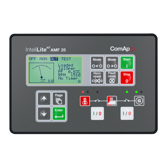
IL-NT Terminals IL-NT terminals and face InteliLite – AMF20/25, SW version 1.2, ©ComAp – March 2008 IL-NT-AMF-Reference Guide1.2.pdf... -
Page 15: Recommended Wiring
Hint: MCB and GCB is recommended to be mechanically interlocked. It is possible to start Volvo and Scania engines via CAN bus. See Engines started via CAN bus. InteliLite – AMF20/25, SW version 1.2, ©ComAp – March 2008 IL-NT-AMF-Reference Guide1.2.pdf... -
Page 16: Stand-By Applications
Stand-by Applications Contactors (set point MCB Logic = “CLOSE-OFF”) LOAD +24V(12V) ATS with two stable positions (set point MCB Logic = “CLOSE-ON”) LOAD +24V(12V) InteliLite – AMF20/25, SW version 1.2, ©ComAp – March 2008 IL-NT-AMF-Reference Guide1.2.pdf... -
Page 17: Ats With Three Stable Positions (Set Point Mcb Logic = "Close-Off")
ATS with three stable positions (set point MCB Logic = “CLOSE-OFF”) LOAD ATS l ATS ll +24V(12V) InteliLite – AMF20/25, SW version 1.2, ©ComAp – March 2008 IL-NT-AMF-Reference Guide1.2.pdf... -
Page 18: Getting Started
5 000 microFarad to withstand 150ms voltage dip under following conditions: Voltage before dip is 12V, after 150ms the voltage recovers to min. allowed voltage, i.e. 8V. Hint: Before the battery is discharged the message "Low BackupBatt" appears. InteliLite – AMF20/25, SW version 1.2, ©ComAp – March 2008 IL-NT-AMF-Reference Guide1.2.pdf... - Page 19 Fuse value and type depends on number of connected devices and wire length. Recommended fuse (not fast) type - T1A. Not fast due to internal capacitors charging during power up. InteliLite – AMF20/25, SW version 1.2, ©ComAp – March 2008 IL-NT-AMF-Reference Guide1.2.pdf...
- Page 20 Use as short as possible cable to the grounding point on the switchboard Use cable min. 2,5mm The “-“ terminal of the battery has to be properly grounded InteliLite – AMF20/25, SW version 1.2, ©ComAp – March 2008 IL-NT-AMF-Reference Guide1.2.pdf...
-
Page 21: Current Measurement
If engine will not start: Check ground connection from pick-up to controllers, eventually disconnect ground connection to one of them Galvanically separate InteliLite RPM input using ComAp separation transformer RPM-ISO (1:1) Use separate pick-up for Speed governor and InteliLite Hint:... -
Page 22: Voltage Measurement
Switchboard lighting strikes protection according standard regulation is expected !!! Current measurement To ensure proper function Use cables of 2,5mm Use transformers to 5A Connect CT according to following drawings. Terminals L2l and L3l are opened. InteliLite – AMF20/25, SW version 1.2, ©ComAp – March 2008 IL-NT-AMF-Reference Guide1.2.pdf... -
Page 23: Analog Inputs
(Valid only for analog inputs) Each Analog input has separate set points for two level alarm setting. Analog input alarm levels and delay adjust in Engine Protect group. InteliLite – AMF20/25, SW version 1.2, ©ComAp – March 2008 IL-NT-AMF-Reference Guide1.2.pdf... - Page 24 Set configuration for Oil Press analog input: Type : selection between Not used and Alarm “Not used” – analog input isn’t used ”Alarm” – analog input is used InteliLite – AMF20/25, SW version 1.2, ©ComAp – March 2008 IL-NT-AMF-Reference Guide1.2.pdf...
- Page 25 Each Analog input has separate triplet of setpoints: Wrn level , Sd level , AI del . Names of these setpoints are fix defined Number of decimal points of Wrn level and Sd level is the same as the configured number of decimal points of measured value. InteliLite – AMF20/25, SW version 1.2, ©ComAp – March 2008 IL-NT-AMF-Reference Guide1.2.pdf...
- Page 26 Binary inputs 4k7 Ω Power Supply Battery Binary outputs LOAD Power Supply Battery InteliLite – AMF20/25, SW version 1.2, ©ComAp – March 2008 IL-NT-AMF-Reference Guide1.2.pdf...
-
Page 27: Extension Modules (Can Bus) Connection
IL- NT – IGS-PTM – IGL-RA15 It is possible to connect only one IG-IOM or IGS-PTM and one IGL-RA15 to IL-CU. button in LiteEdit configuration window to activate CAN (J1939) interface. InteliLite – AMF20/25, SW version 1.2, ©ComAp – March 2008 IL-NT-AMF-Reference Guide1.2.pdf... -
Page 28: Analog Outputs
PWM signal emulates sensor which would be typically mounted on the engine. Any value from controler may be configured to the outputs. Use LiteEdit PC SW to configure coresponding sensor/gauge curve and value selection. InteliLite – AMF20/25, SW version 1.2, ©ComAp – March 2008 IL-NT-AMF-Reference Guide1.2.pdf... -
Page 29: Inputs And Outputs
This input indicates whether MCB is closed or opened. Emergency Stop If the input is opened, shut down is immediately activated. Input is inverted (normally closed) in default configuration. InteliLite – AMF20/25, SW version 1.2, ©ComAp – March 2008 IL-NT-AMF-Reference Guide1.2.pdf... - Page 30 Function Test Onload was changed to combination Remote Test + Rem TEST OnLd. RemControlLock If the input is active, setpoints writing or command sending from the external terminal is disabled. InteliLite – AMF20/25, SW version 1.2, ©ComAp – March 2008 IL-NT-AMF-Reference Guide1.2.pdf...
- Page 31 If the input is closed, the automatic start of the gen-set at Mains failure is blocked. In case of running gen-set the GCB is opened, gen-set goes to Cooling procedure and stops. The input simulates healthy Mains. InteliLite – AMF20/25, SW version 1.2, ©ComAp – March 2008 IL-NT-AMF-Reference Guide1.2.pdf...
-
Page 32: Binary Outputs Il-Nt - Default
Stop Solenoid can still be active (in that case it is deactivated before cranking). Stop Pulse Output is active for 1 second after S top Solenoid output activation. This signal is sent to ECU in case of engine stop request. InteliLite – AMF20/25, SW version 1.2, ©ComAp – March 2008 IL-NT-AMF-Reference Guide1.2.pdf... - Page 33 The output controls the generator circuit breaker. Hint: Supposed time to close (reaction time) of GCB is 0,1 sec. GCB ON Coil The output activates Generator Circuit Breaker coil. InteliLite – AMF20/25, SW version 1.2, ©ComAp – March 2008 IL-NT-AMF-Reference Guide1.2.pdf...
- Page 34 • alarm is not active and • FAULT RESET is pressed AL Gen Volts The output closes if the generator over/under voltage alarm or voltage asymmetry alarm activates. InteliLite – AMF20/25, SW version 1.2, ©ComAp – March 2008 IL-NT-AMF-Reference Guide1.2.pdf...
- Page 35 FAULT RESET is pressed AL Overspeed Output closes if the gen-set overspeed alarm activates. The output opens, if • alarm is not active and • FAULT RESET is pressed InteliLite – AMF20/25, SW version 1.2, ©ComAp – March 2008 IL-NT-AMF-Reference Guide1.2.pdf...
- Page 36 Output closes if the water temperature (configured to the second analog input) warning alarm activates. The output opens, if • alarm is not active and • FAULT RESET is pressed InteliLite – AMF20/25, SW version 1.2, ©ComAp – March 2008 IL-NT-AMF-Reference Guide1.2.pdf...
- Page 37 Treshhold level for D+ input is 80% supply voltage. Maintenance Output closes if the Maintenance alarm activates, i.e. the gen-set has been running for more than Engine Protect : Maintenance . The output opens, if InteliLite – AMF20/25, SW version 1.2, ©ComAp – March 2008 IL-NT-AMF-Reference Guide1.2.pdf...
- Page 38 ECU. If the output is configured (which means configured on physical binary output or VPIO output), the issuing of communication error is blocked during Prestart and Stopping procedure as shown in the picture. InteliLite – AMF20/25, SW version 1.2, ©ComAp – March 2008 IL-NT-AMF-Reference Guide1.2.pdf...
-
Page 39: Analog Inputs
Water temperature analog input. Default range 0 to 120 ° C. Fuel Level Fuel level analog input. Default VDO sensor 0-180R = 0-100% Hint: For further information about analog inputs’ configuration see Analog inputs. InteliLite – AMF20/25, SW version 1.2, ©ComAp – March 2008 IL-NT-AMF-Reference Guide1.2.pdf... - Page 40 Use LiteEdit 3.0 to enable/disable J1939 interface and to configure IL-NT analog inputs. Hint: RPM reading is automatically switched to pickup or generator voltage measuring (depends on Basic Settings : Gear Teeth value) if J1939 fails. InteliLite – AMF20/25, SW version 1.2, ©ComAp – March 2008 IL-NT-AMF-Reference Guide1.2.pdf...
-
Page 41: Setpoints
WARNING! When you change the firmware, statistics can be invalid! PT Ratio [/1] Gen-set potential transformers ratio. Step: 0,1 V / V Range: 0,1 – 500,0 V / V InteliLite – AMF20/25, SW version 1.2, ©ComAp – March 2008 IL-NT-AMF-Reference Guide1.2.pdf... - Page 42 From LiteEdit it is only possible to connect to controllers with address 1. COM1 Mode [STANDARD/MODBUS/CUMMINS] Communication protocol switch. COMAP: LiteEdit communication protocol. Modbus: Modbus protocol. CumminsMB: Protocol for communication with Cummins engines via Modbus. InteliLite – AMF20/25, SW version 1.2, ©ComAp – March 2008 IL-NT-AMF-Reference Guide1.2.pdf...
-
Page 43: Engine Params
During the Idle time timer running the binary output Idle/Nominal is opened when it elapses the Idle/Nominal output closes. Binary output Idle/Nominal opens during Cooling period again. Step: Range: 0 – 600 s InteliLite – AMF20/25, SW version 1.2, ©ComAp – March 2008 IL-NT-AMF-Reference Guide1.2.pdf... - Page 44 Determines behavior of the Binary output FUEL SOLENOID. DIESEL: Output closes 1 sec before Binary output STARTER. The output opens if Emergency Stop comes or Cooled gen-set is stopped and in pause between repeated starts. InteliLite – AMF20/25, SW version 1.2, ©ComAp – March 2008 IL-NT-AMF-Reference Guide1.2.pdf...
-
Page 45: Engine Protect
During the start of the gen-set, some engine protections have to be blocked (e.g. Oil pressure). The protections are unblocked after the ProtectHoldoff time. The time starts after reaching Starting RPM . InteliLite – AMF20/25, SW version 1.2, ©ComAp – March 2008 IL-NT-AMF-Reference Guide1.2.pdf... - Page 46 AI2 Del Delay for ANALOG INPUT 2 alarm. Step: Range: 0 – 180 s AI3 Wrn Warning threshold level for ANALOG INPUT 3 Step: Range: -100 – 10000 InteliLite – AMF20/25, SW version 1.2, ©ComAp – March 2008 IL-NT-AMF-Reference Guide1.2.pdf...
-
Page 47: Gener Protect
IDMT curve shape selection. Amps IDMT Del is Reaction time of IDMT protection for 200% overcurrent Igen = 2* Nomin Current . Step: 0,1 s Range: 0,1 - 60,0 s InteliLite – AMF20/25, SW version 1.2, ©ComAp – March 2008 IL-NT-AMF-Reference Guide1.2.pdf... - Page 48 Amps Unbal Sd Threshold for generator current asymmetry (unbalance). Step: 1% of Nominal current Range: 1 – 200% of Nominal current Amps Unbal Del Delay for generator current unbalance InteliLite – AMF20/25, SW version 1.2, ©ComAp – March 2008 IL-NT-AMF-Reference Guide1.2.pdf...
-
Page 49: Automains Fail
EmergStart Del Delay after the mains failure to the start of the gen-set Step: Range: 0 – 600 s MainsReturnDel Delay after the mains return to the GCB opening. InteliLite – AMF20/25, SW version 1.2, ©ComAp – March 2008 IL-NT-AMF-Reference Guide1.2.pdf... - Page 50 Delay for mains undervoltage and overvoltage Step: 0.1 s Range: 0 – 600.0 s Mains V Unbal Threshold for mains voltage unbalance Step: 1% of Nominal voltage Range: 1 – 150% InteliLite – AMF20/25, SW version 1.2, ©ComAp – March 2008 IL-NT-AMF-Reference Guide1.2.pdf...
- Page 51 “ON ” Mains O.K. Mains O.K. MCB logic = ”CLOSE-ON” Mains Failure Signal after external MCB logic = ”CLOSE-OFF” inverted relay AUX. INVERTING RELAY DO 4 Battery InteliLite – AMF20/25, SW version 1.2, ©ComAp – March 2008 IL-NT-AMF-Reference Guide1.2.pdf...
-
Page 52: Date/Time
WINTER (SUMMER) : Automatic switching between summer and wintertime is enabled and it is set to winter (summer) season. WINTER-S (SUMMER-S) : Modification for southern hemisphere. #Time [HHMMSS] Real time clock adjustment. InteliLite – AMF20/25, SW version 1.2, ©ComAp – March 2008 IL-NT-AMF-Reference Guide1.2.pdf... -
Page 53: Sensor Spec
When the actual value of fuel level is higher or equals to this value then the binary output Fuel Pump is deactivated. Step: Range: 0 – 100 % InteliLite – AMF20/25, SW version 1.2, ©ComAp – March 2008 IL-NT-AMF-Reference Guide1.2.pdf... -
Page 54: Extension I/O
Set this setpoint to YES if you want to get messages when a red alarm occurs. Hint The target address (GSM phone number or e-mail address) must be set correctly to the setpoint(s) TelNo /Addr Ch1 resp. TelNo /Addr Ch2 . InteliLite – AMF20/25, SW version 1.2, ©ComAp – March 2008 IL-NT-AMF-Reference Guide1.2.pdf... - Page 55 There are 5 attempts for any active call. Timeout for connection is 90 sec and after 120 sec controller starts the next attempt. During the time the IL-NT is trying to send an active call type, incoming calls are blocked. InteliLite – AMF20/25, SW version 1.2, ©ComAp – March 2008 IL-NT-AMF-Reference Guide1.2.pdf...
-
Page 56: Ecu-Controlled Engine Support
The actual list of ECU types is available on ComAp website in "ECU list - x.y.iwe" package. Download this package and import it into LiteEdit in the same way as standard firmware IWE package. -
Page 57: Values Read From Ecu
• SAE Truck and Bus Control and Communications Network Standards Manual, SAE HS-1939 Publication • Or refer to corresponding engine manufacturer’s ECU error codes list. Complete list of text diagnostic messages for each ECU can be found in Comap Electronic Engines Support manual. Hint: InteliLite controller doesn’t support J1587 diagnostic line on Volvo engines. -
Page 58: Analog Inputs
MAINS C.B. FEED -BACK GEN C.B. FEED-BACK CONTROL SIGNALS ALARM READY TO LOAD PRESTART MAINS C.B. GEN C.B. BO ECU PwrRelay BO ECU CommOK (EDCIII) / ECU CommError (EMSII) FUEL LEVEL InteliLite – AMF20/25, SW version 1.2, ©ComAp – March 2008 IL-NT-AMF-Reference Guide1.2.pdf... - Page 59 REMOTE OFF ACCESS LOCK EMERGENCY STOP MAINS C.B. FEED -BACK GEN C.B. FEED-BACK CONTROL SIGNALS ALARM READY TO LOAD PRESTART MAINS C.B. GEN C.B. +24 V DC FUEL LEVEL InteliLite – AMF20/25, SW version 1.2, ©ComAp – March 2008 IL-NT-AMF-Reference Guide1.2.pdf...
- Page 60 CONTROL SIGNALS ALARM READY TO LOAD PRESTART MAINS C.B. GEN C.B. GND (PIN 20) RS485 - (PIN 18) RS485 + (PIN 21) TERM2 (PIN 19) TERM1 (PIN 22) InteliLite – AMF20/25, SW version 1.2, ©ComAp – March 2008 IL-NT-AMF-Reference Guide1.2.pdf...
-
Page 61: Sensor Specification
VDO Fuel % Hint: When measured value is 6% out of range the Sensor fail FLS is detected. You can find detail information on sensores in LiteEditu Reference Guide. InteliLite – AMF20/25, SW version 1.2, ©ComAp – March 2008 IL-NT-AMF-Reference Guide1.2.pdf... -
Page 62: Function Description
< 10V, D+ not Active no shutdown alarm active, other than OFF Mode selected Prestart Prestart time elapsed STARTER on Cranking FUEL SOLENOID on MaxCrank Time counter started InteliLite – AMF20/25, SW version 1.2, ©ComAp – March 2008 IL-NT-AMF-Reference Guide1.2.pdf... - Page 63 Fuel solenoid is switched on with time advance of 1s fixed before starter motor is switched on. Hint: Threshold level for D+ input is 80% supply voltage, activation delay is 1s (to override short firings during cranking – for example in cold conditions). InteliLite – AMF20/25, SW version 1.2, ©ComAp – March 2008 IL-NT-AMF-Reference Guide1.2.pdf...
-
Page 64: Aut Mode
Caution: The gen-set starts automatically and is always running in TEST mode! The setpoint ReturnFromTEST = MANUAL While TEST mode is selected, gen-set starts and is running unloaded. InteliLite – AMF20/25, SW version 1.2, ©ComAp – March 2008 IL-NT-AMF-Reference Guide1.2.pdf... -
Page 65: Circuit Breakers Timing
When MCB feedback drop-out and measured mains electrical limits (voltage, frequency) are still in limits, the controller switches MCB ON again. Mains fail opened Mains V Del or Mains Freq Del or Mains VUnb Del genset start EmergStart Del InteliLite – AMF20/25, SW version 1.2, ©ComAp – March 2008 IL-NT-AMF-Reference Guide1.2.pdf... - Page 66 Situation 2 : ReturnFromTEST =MANUAL, Mains =OK, MCB is closed, gen-set is running. Press MCB on/off -> MCB opens, GCB closes ( Fwd Return Del ), gen-set is running loaded. MCB opened GCB closed Fwd Return Del InteliLite – AMF20/25, SW version 1.2, ©ComAp – March 2008 IL-NT-AMF-Reference Guide1.2.pdf...
-
Page 67: Alarm Management
Mains failure detection depends on Auto mains failure setpoints (levels and delays) adjusting. When the mains failure comes up, mains circuit breaker is opened. Possible mains failure reasons: List of possible events Hint: Mains failure is not written to alarm list! InteliLite – AMF20/25, SW version 1.2, ©ComAp – March 2008 IL-NT-AMF-Reference Guide1.2.pdf... - Page 68 100% Failure Failure Range of sensor GCB, MCB fail detection MCB or GCB fail detection is based on binary output CB close/open comparing with binary input CB feedback. InteliLite – AMF20/25, SW version 1.2, ©ComAp – March 2008 IL-NT-AMF-Reference Guide1.2.pdf...
- Page 69 Time delay closed 5 or 2 sec BI G CB feedback active Alarm: GCB fail Hint: You can solve state of MCB fail by pressing Fault Reset button. InteliLite – AMF20/25, SW version 1.2, ©ComAp – March 2008 IL-NT-AMF-Reference Guide1.2.pdf...
-
Page 70: Gen-Set Operation States
Warning alarm configurable on the input of IG-IOM/IGS-PTM. IOM AIx Sd Shutdown alarm configurable on the input of IG-IOM/IGS-PTM. Binary input Configurable Configurable Warning/Shutdown alarms on the inputs of IL-NT. InteliLite – AMF20/25, SW version 1.2, ©ComAp – March 2008 IL-NT-AMF-Reference Guide1.2.pdf... - Page 71 *Sd IOM Fail Shutdown alarm in case of lost connection to IG-IOM/IGS-PTM module. Wrn ECU Alarm ECU alarm list is not empty Low BackupBatt RTC backup battery is flat InteliLite – AMF20/25, SW version 1.2, ©ComAp – March 2008 IL-NT-AMF-Reference Guide1.2.pdf...
-
Page 72: History File
IG-IOM, IGS-PTM Binary inputs (when configured IG-IOM, IGS-PTM) BINARY Binary outputs IL-NT OUTPUTS IG-IOM, IGS-PTM Binary outputs (when configured IG-IOM, IGS-PTM) ECU alarm FailureCode ECUalarm Failure Mode Identifier InteliLite – AMF20/25, SW version 1.2, ©ComAp – March 2008 IL-NT-AMF-Reference Guide1.2.pdf... -
Page 73: Remote Control And Data Logging
Required the same voltage potential between GND‘s Battery PC software – LiteEdit On the PC (for direct or modem connection) has to be installed the ComAp’s software package LiteEdit. (based on Windows 95 or newer platform) LiteEdit enables: • read the quantities •... - Page 74 Min Stab Time 8259 Unsigned 16 Engine Params Max Stab Time 8313 Unsigned 16 Engine Params Cooling Time 8258 3600 Unsigned 16 Engine Params Stop Time 9815 Unsigned 16 InteliLite – AMF20/25, SW version 1.2, ©ComAp – March 2008 IL-NT-AMF-Reference Guide1.2.pdf...
- Page 75 Fwd Return Del 8303 600,0 Unsigned 16 AutoMains Fail MCB Close Del 8389 60,0 Unsigned 16 AutoMains Fail Mains >V 8305 Unsigned 16 AutoMains Fail Mains <V 8307 Unsigned 16 InteliLite – AMF20/25, SW version 1.2, ©ComAp – March 2008 IL-NT-AMF-Reference Guide1.2.pdf...
- Page 76 Sensors Spec IOM AI4 Calibr 8796 -1000 1000 Integer 16 Sensors Spec Fuel Pump ON 10100 -100 Integer 16 Sensors Spec Fuel Pump OFF 10101 10000 Integer 16 InteliLite – AMF20/25, SW version 1.2, ©ComAp – March 2008 IL-NT-AMF-Reference Guide1.2.pdf...
- Page 77 Generator Gen V L1-L2 9628 Unsigned 16 Generator Gen V L2-L3 9629 Unsigned 16 Generator Gen V L3-L1 9630 Unsigned 16 Generator Gen A L1 8198 Unsigned 16 InteliLite – AMF20/25, SW version 1.2, ©ComAp – March 2008 IL-NT-AMF-Reference Guide1.2.pdf...
- Page 78 ##### 24553 Date In case of software malfunction DiagData shows the value that enables to locate possible bug in software. Include this number when reporting a software problem. InteliLite – AMF20/25, SW version 1.2, ©ComAp – March 2008 IL-NT-AMF-Reference Guide1.2.pdf...
-
Page 79: Remote Communication
Analog modem modem modem modem Mobile SIM card setting • Adjust SIM card in GSM modem following way: • enable data connection (when required) • no PIN code InteliLite – AMF20/25, SW version 1.2, ©ComAp – March 2008 IL-NT-AMF-Reference Guide1.2.pdf... -
Page 80: Technical Data
Technical data IL-NT Standard Order code:IL-NT-xxxxx LT Operating temperature C..+70 C..+70 Storage temperature C..+80 C..+80 Preheating foil increases controller current consumption Controller No preheating Preheating at ambient temperature InteliLite – AMF20/25, SW version 1.2, ©ComAp – March 2008 IL-NT-AMF-Reference Guide1.2.pdf... -
Page 81: Dimensions And Weight
Number of outputs Maximum current 0,5 A Maximum switching voltage 36 VDC Analog inputs Not electrically separated Number of inputs Resolution 10 bits Jumper selectable range V, Ohm(default), mA InteliLite – AMF20/25, SW version 1.2, ©ComAp – March 2008 IL-NT-AMF-Reference Guide1.2.pdf... -
Page 82: Speed Pick-Up Input
3105A Paired EIA Industrial RS485 cable LAPP CABLE (see http://www.lappcable.com) • Unitronic BUS DeviceNet Trunk Cable • Unitronic BUS DeviceNet Drop Cable • Unitronic BUS CAN • Unitronic-FD BUS P CAN UL/CSA InteliLite – AMF20/25, SW version 1.2, ©ComAp – March 2008 IL-NT-AMF-Reference Guide1.2.pdf... -
Page 83: Il-Nt Rs232 Interface (Optional Card)
2,5 % ± 0,5mA out of measured value Current measurement tolerance IGL-RA15 Power supply Voltage supply 8-36V DC Consumption 0,35-0,1A (+1A max horn output) Depend on supply voltage InteliLite – AMF20/25, SW version 1.2, ©ComAp – March 2008 IL-NT-AMF-Reference Guide1.2.pdf... -
Page 84: Ig-Ib
95 x 96 x 43 mm , DIN rail (35 mm) mounted Interface to controller RS232 Interface to modem RS232 Interface to Ethernet RJ45 (10baseT) Operating temperature -30..+70 Storage temperature -30..+70 InteliLite – AMF20/25, SW version 1.2, ©ComAp – March 2008 IL-NT-AMF-Reference Guide1.2.pdf...
Need help?
Do you have a question about the InteliLite NT AMF Series and is the answer not in the manual?
Questions and answers