Table of Contents
Advertisement
Quick Links
IMPORTANT
Read this manual thoroughly, and do not perform
installation, operation, maintenance, or inspection
unless you fully understand all of the contents.
Keep this manual in a safe place where you can refer
to it easily while installing, operating, and carrying out
maintenance or inspections.
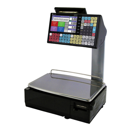
UNI-5
Service Manual
2nd Edition
Issued on 2-Mar-2012
Advertisement
Table of Contents

Subscribe to Our Youtube Channel
Related Manuals for ISHIDA UNI-5


Summary of Contents for ISHIDA UNI-5
- Page 1 UNI-5 Service Manual 2nd Edition IMPORTANT Read this manual thoroughly, and do not perform installation, operation, maintenance, or inspection unless you fully understand all of the contents. Issued on 2-Mar-2012 Keep this manual in a safe place where you can refer to it easily while installing, operating, and carrying out maintenance or inspections.
- Page 2 © ISHIDA Co., Ltd. 2012 All rights are reserved. No part of this publication may be reproduced, stored in a retrieval system, or transmitted in any form or by any means mechanical, electronic, photocopying, recording, or otherwise without prior written permission of ISHIDA.
- Page 3 ISHIDA is not liable for any damage, loss or injury that results from incorrect operation, insufficient caution, unauthorized modifications to the machine, or failure to follow the instructions contained in this manual.
- Page 4 Additionally, there may be significant property damage. Indicates a potentially hazardous situation where, if not avoided, may result in minor or moderate injury or in property damage. Indicates reference information for operation. Indicates the referred page for operation. UNI-5 Service Manual...
- Page 5 Dropping the machine may result in injury or cause the machine to break down. Do not drop the cassette. Dropping the cassette may result in injury or cause the cassette to break down. UNI-5 Service Manual...
- Page 6 Do not press the touch panel with an edged thing. Doing so may scratch the panel and cause the machine to break down. Do not dispose of batteries with normal household waste. Please obey your local regulations when disposing of used batteries. UNI-5 Service Manual...
- Page 7 Do not give the victim anything to drink, and do not rinse the mouth. If vomiting occurs naturally, have the victim lean forward to reduce risk of aspiration. Keep the victim warm and seek medical attention. UNI-5 Service Manual...
-
Page 8: Table Of Contents
LCD BOARD (PK-263) ................... 4-8 WIRELESS LAN BOARD (PK-265) ..............4-9 SELF-SERVICE MASTER BOARD (PK-266) ..........4-10 SELF-SERVICE MASTER BOARD (PK-267) ..........4-11 THERMAL BOARD (PK-268) ............... 4-12 THERMAL CONNECTOR BOARD (PK-268) ..........4-14 SCALE BOARD (PK-999) ................4-16 UNI-5 Service Manual... - Page 9 OPERATION PANEL UNIT ..............5-19 5.4.2 CUSTOMER DISPLAY UNIT ..............5-21 5.4.3 ELEVATED UNIT ..................5-22 Chapter 6 MECHANICAL ADJUSTMENT FOUR CORNER LIMIT SPACE ..............6-1 GEAR ENGAGEMENT ................... 6-2 PRINT POSITION .................... 6-3 THERMAL HEAD POSITION ................6-4 UNI-5 Service Manual...
-
Page 10: Chapter 1 Basic Information
Chapter 1 BASIC INFORMATION BASIC INFORMATION OUTER DIMENSIONS FOR EACH TYPE 1.1.1 OUTER DIMENSIONS FOR BENCH TYPE UNI-5 Service Manual... -
Page 11: Outer Dimensions For Pole Type
Chapter 1 BASIC INFORMATION 1.1.2 OUTER DIMENSIONS FOR POLE TYPE UNI-5 Service Manual... -
Page 12: Outer Dimensions For Elevated Type
Chapter 1 BASIC INFORMATION 1.1.4 OUTER DIMENSIONS FOR ELEVATED TYPE UNI-5 Service Manual... -
Page 13: Specifications
Note: The printing speed may vary according to label conditions. Printing effective size 56mm Label size Label width: 30mm to 60mm Label length: 20mm to 150mm Input/Output LAN 1 channel USB 1 channel CF 1 channel Drawer 2 channels Program store medium Flash ROM (32M bytes) UNI-5 Service Manual... -
Page 14: Installation
To avoid personal injury and shock, do not open or remove any covers or enclosures of the machine unless specified in the manual. Do not perform unspecified maintenance. For your personal safety, do not perform any maintenance procedures which are not specified in the manual. UNI-5 Service Manual... -
Page 15: Precautions For Installation
Places exposed to direct cold sunlight fluctuations Places where water or other air from air conditioners or liquids are easily spilled on the refrigerators Places where the floor or machine foundation is unstable UNI-5 Service Manual... -
Page 16: Chapter 2 Assembly Drawings
Chapter 2 ASSEMBLY DRAWINGS ASSEMBLY DRAWINGS BENCH TYPE UNI-5 Service Manual... - Page 17 ACCESSORY PCB SUPPORT HARNESS C3 SENSOR BRACKET LCD COVER PRINTER LCD TOUCH MAGNETIC CASE FRONT CONTROLL STICKER LABEL SETTING KEY BOARD MEMBRANE BRACKET LABEL PEEL SHEET KEY BOARD-SETTING PLATE A COVER COVER KEY BOARD FRONT LCD ASSY UNI-5 Service Manual...
-
Page 18: Pole Type
Chapter 2 ASSEMBLY DRAWINGS POLE TYPE UNI-5 Service Manual... - Page 19 KEY BOARD MEMBRANE HARNESS C3 SENSOR SHEET KEY BOARD-SETTING MAGENT COVER KEY BOARD STICKER LABEL SETTING BRACKET CONNECTOR ASSY STICKER IMPORTANT PWB PK-265A BRACKET LABEL PEEL HARNESS C4 SWITCH ASSY PLATE A COVER COVER SWITCH FRONT LCD ASSY UNI-5 Service Manual...
-
Page 20: Elevated Single Printer Type
KEY BOARD MEMBRANE BRACKET LCD CASE FRONT CONTROLL ACCESSORY PCB SUPPORT LCD TOUCH PWB PK-263A SHEET DOUBLE TAPE CASE REAR POLE DISPLAY GASKET 115mm HINGE R COLLAR SPACER COVER JOINT REAR PWB PK-261A COVER KEY BOARD CASE PRINTER UNI-5 Service Manual... - Page 21 NAME PLATE SPEC BRACKET HINGE NAME PLATE SERIAL COVER FRONT ELEVATE MAGENT POWER SUPPLY STICKER LABEL SETTING BRACKET POWER STICKER IMPORTANT CASE REAR POLE DISPLAY BRACKET LEVEL COVER BRACKET CONNECTOR PLATE A COVER COVER SWITCH FRONT LCD ASSY UNI-5 Service Manual...
- Page 22 Chapter 2 ASSEMBLY DRAWINGS PRINTER FOR EACH TYPE UNI-5 Service Manual...
- Page 23 LEVER HANDLE BRACKET SENSOR PLATE B LEVER BLOCK B LOCK BUSH LEVER COLLAR BLOCK B LEVER BRACKET MAGNET SHAFT LEVER COVER PRINTER FRAME COVER ROLL FRAME PRINTER STOPPER HOLDER LABEL CABLE CLAMPS SHAFT STEP BOBBIN HARNESS C2 HEAD UNI-5 Service Manual...
-
Page 24: Chapter 3 Block Diagrams
Chapter 3 BLOCK DIAGRAMS BLOCK DIAGRAMS BLOCK DIAGRAM (BENCH/POLE/EV1 TYPE) UNI-5 Service Manual... -
Page 25: Chapter 4 Electrical Signals
DC+15V power supply for LCD backlight 28,29 Light control signal for LCD backlight ← External buzzer signal → → 32,33 DC+5V 34 - 39 Membrane key control signal ←→ XJ20 Signal Name Direction Opposite Side 1 - 14 Debug signal ←→ Unused UNI-5 Service Manual... - Page 26 AC power supply for LCD PK-263(XJ1) DC-10V power supply for LCD DC+15V power supply for LCD DC+15V power supply for LCD backlight 27,28 Light control signal for LCD backlight → 24,25 DC+5V Signal Name Direction Opposite Side DC+12V P-999 UNI-5 Service Manual...
- Page 27 *default 1-2short External BAT+ XJ10 Signal Name Direction Opposite Side BAT+ Unused Signal Name Direction Opposite Side DC+5V PK-265(XJ1) XJ22 Signal Name Direction Opposite Side DC+5V → Unused → ← ← Signal Name Direction Opposite Side DC+5V Unused UNI-5 Service Manual...
- Page 28 → DC+24V XJ15 Signal Name Direction Opposite Side Peel sensor DC+5V Peel sensor ← SENS_IN Peel sensor Label sensor Peel sensor DC+3.3V Label sensor Label sensor LED_GND Label sensor LED_VCC Label sensor ← SENS_IN Label sensor 8,9,10 UNI-5 Service Manual...
- Page 29 Signal Name Direction Opposite Side 1,2,3 DC+24V main power supply Switching power supply 4,5,6 XJ12 Signal Name Direction Opposite Side DC+24V Unused Signal Name Direction Opposite Side USB_VBUS USB_D+ ←→ USB_D- ←→ USB_GND NONE Unused VBUS ←→ ←→ UNI-5 Service Manual...
-
Page 30: Key/Lcd Board (Pk-261)
DC+15V power supply LCD backlight 28,29 Light control signal for LCD backlight ← External buzzer signal → Vibration signal → 32,33 DC+5V 34 - 39 Membrane key control signal ←→ Signal Name Direction Opposite Side → Unused DC+5V UNI-5 Service Manual... - Page 31 Key scanning 1,2,3,4, → 5,6,7,8 KS0 - KS7 9,10,11,12, Key data Membrane key 13,14,15,16, ← KD0 - KD10 17,18,19 Unused Signal Name Direction Opposite Side DC+5V Unused XJ10,11 Signal Name Direction Opposite Side DC+5V for vibration Unused UNI-5 Service Manual...
-
Page 32: Lcd Board (Pk-263)
1,21 DC+5V power supply for LCD LCD GND 10,11 AC power supply for LCD DC-10V power supply for LCD DC+15V power supply for LCD Others LCD control signal ←→ Signal Name Direction Opposite Side DC+5V LCD backlight UNI-5 Service Manual... -
Page 33: Wireless Lan Board (Pk-265)
Chapter 4 ELECTRICAL SIGNALS WIRELESS LAN BOARD (PK-265) Signal Name Direction Opposite Side DC+5V PK-270 XJ7 Signal Name Direction Opposite Side → → ← ← PK-270 XJ2 LEDR LEDL 4,7,13,14 9,12 DC+3.3V UNI-5 Service Manual... -
Page 34: Self-Service Master Board (Pk-266)
3,4,5,6 Membrane key control signal ←→ Signal Name Direction Opposite Side Key scan 1,2,3,4,5,6 → KS0 - KS5 Membrane key Key data 7,8,9,10,11,12 ← KD0 - KD5 XJ6/XJ7 Signal Name Direction Opposite Side DC+5V Vibration unit 4-10 UNI-5 Service Manual... -
Page 35: Self-Service Master Board (Pk-267)
SELF-SERVICE MASTER BOARD (PK-267) Signal Name Direction Opposite Side DC+5V PK-266 XJ3/XJ4 3,4,5,6 Membrane key control signal ←→ Signal Name Direction Opposite Side Key scan 1,2,3,4,5,6 → KS0 - 5 Membrane key Key data 7,8,9,10,11,12 ← KD0 - 5 UNI-5 Service Manual 4-11... -
Page 36: Scale Board (Pk-999)
Chapter 4 ELECTRICAL SIGNALS SCALE BOARD (PK-999) Signal Name Direction Opposite Side DC+12V ・PK-270 XJ6 Not connected Not connected Not connected 4-12 UNI-5 Service Manual... -
Page 37: Chapter 5 Machine Disassembly
Remove the five screws (blue), two tapping Remove the upper case. screws (red), and one TP screw (green). Weigh platter holder Upper case * Reverse this procedure for assembly. UNI-5 Service Manual... -
Page 38: Weigh Platter Holder
(Refer to section 5.1.1) platter holder. Weigh platter holder Motor STP-29D1026 Remove the weigh platter holder. Motor STP-29D1026 Power supply ZWS150PAF-24/J AD board P-999 (in the die-cast) Load cell CLC-25N Main board PK-260 * Reverse this procedure for assembly. UNI-5 Service Manual... -
Page 39: Main Board
Chapter 5 MACHINE DISASSEMBLY 5.1.3 MAIN BOARD Remove the three screws fixing the main Unplug all harnesses connected to the main board. board. Squeeze the two spacers to remove the main board. Reverse this procedure for assembly. UNI-5 Service Manual... -
Page 40: Operation Panel
Remove the bottom case of the operation the bottom of the operation panel. panel. Bottom case Unplug all harnesses and remove the fixing Unplug the harnesses. screws to detach the touch panel LCD with the bracket. Display/ Key control board PK-261 UNI-5 Service Manual... - Page 41 Chapter 5 MACHINE DISASSEMBLY TFT touch panel LCD Membrane keys * Reverse this procedure for assembly. UNI-5 Service Manual...
-
Page 42: Customer Display
Weigh platter holder Remove the weigh platter holder and unplug Detach the customer display unit. the harness connected with the main board. Remove the fixing screws to detach the Unplug the harnesses. display LCD with the bracket. UNI-5 Service Manual... - Page 43 Chapter 5 MACHINE DISASSEMBLY Detach the display control board and TFT LCD. TFT LCD Display control board AT070TN07 PK-263 * Reverse this procedure for assembly. UNI-5 Service Manual...
-
Page 44: Label Sensor
Chapter 5 MACHINE DISASSEMBLY 5.1.6 LABEL SENSOR This photo shows the label sensor. Label sensor * Reverse this procedure for assembly. 5.1.7 PEEL SENSOR This photo shows the peel sensor. Peel sensor * Reverse this procedure for assembly. UNI-5 Service Manual... -
Page 45: Thermal Head Unit
Squeeze the springs by holding up the head Unplug the connector and remove the two unit and pull out the thermal head unit. screws. This photo shows the breakdown of the thermal head unit. * Reverse this procedure for assembly. UNI-5 Service Manual... -
Page 46: Load Cell & A/D Board
Remove the two hexagon socket head Remove the two screws to remove the bolts at the other end and detach the load die-cast bracket. cell unit. Unplug the harnesses and squeeze the two spacers (green) to detach the AD board. 5-10 UNI-5 Service Manual... -
Page 47: Power Supply Unit
Disengage the five hooks at the bottom of Detach the customer display unit and remove the machine using a slotted screwdriver. the two screws fixing the power supply unit. Remove the power supply unit. * Reverse this procedure for assembly. UNI-5 Service Manual 5-11... -
Page 48: Motor Unit
Chapter 5 MACHINE DISASSEMBLY 5.1.11 MOTOR UNIT This photo shows the motor unit. Reverse this procedure for assembly. 5-12 UNI-5 Service Manual... -
Page 49: Wireless Lan Unit
Turn to remove the antenna. and the LAN cable are unplugged. When removing the LAN board, remove This photo shows the constituent parts for the two screws. the wireless LAN unit. * Reverse this procedure for assembly. UNI-5 Service Manual 5-13... -
Page 50: Pole Type
Rear case Unplug the display harness connector on the main board to remove the pole unit. * Reverse this procedure for assembly. 5-14 UNI-5 Service Manual... -
Page 51: Customer Display Unit
Detach the front panel of the customer case of the customer display unit. display unit. Unplug the connector. Remove the two screws and unplug the two harnesses. Display control board PK-263 Remove the display control board. * Reverse this procedure for assembly. UNI-5 Service Manual 5-15... -
Page 52: Self-Service Type
Remove the screw fixing the cable clamp and self-service panel unit so that you can work the grounding terminal. from the bottom. Remove the two screws fixing the blind Detach the blind plate and unplug the plate. connector. Blind plate 5-16 UNI-5 Service Manual... - Page 53 Chapter 5 MACHINE DISASSEMBLY Remove the two screws fixing the cable clamps. Separate the self-service panel unit from the machine. Self-service panel unit UNI-5 Service Manual 5-17...
-
Page 54: Panel Control Board
5.3.2 PANEL CONTROL BOARD Lift to disengage the two hooked places and detach the blind cover of the self-service panel unit.. Blind cover Remove the four screws to detach the rear cover. Rear cover Panel control board 5-18 UNI-5 Service Manual... -
Page 55: Elevated Type
R emove the screw located on the bottom of , peel off the blind plate. the operation panel unit. Operation panel Remove the two screws fixing the roll Pull out the holder. holder. UNI-5 Service Manual 5-19... - Page 56 Chapter 5 MACHINE DISASSEMBLY Remove the screw fixing the operation Detach the operation panel. panel. 5-20 UNI-5 Service Manual...
-
Page 57: Customer Display Unit
Remove the two screws fixing the customer Remove the two screws (blue) and loosen display unit. the other two screws (green). Roll holder Detach the customer display unit and Open the customer display unit. remove the four fixing screws. UNI-5 Service Manual 5-21... -
Page 58: Elevated Unit
Chapter 5 MACHINE DISASSEMBLY 5.4.3 ELEVATED UNIT Turn to remove the level adjusting foot. Remove the three screws fixing the pole bottom cover. Remove the three hexagon socket head bolts fixing the elevated unit. 5-22 UNI-5 Service Manual... -
Page 59: Chapter 6 Mechanical Adjustment
Chapter 6 MECHANICAL ADJUSTMENT MECHANICAL ADJUSTMENT FOUR CORNER LIMIT SPACE Adjust the limit spaces at four corners of the weigh platter holder to become the following values. (1) 2mm, (2) 2mm, (3) 2.5mm, (4) 3.2mm Weigh platter holder UNI-5 Service Manual... -
Page 60: Gear Engagement
Chapter 6 MECHANICAL ADJUSTMENT GEAR ENGAGEMENT Make sure that the weigh platter holder is removed. Loose the two screws to move the pulley to the appropriate position for better engagement. Be sure to tighten the screws after adjustment. UNI-5 Service Manual... -
Page 61: Print Position
This photo shows the position of the thermal head unit. Thermal head unit Loosen the two screws and move the thermal head unit back and forth and around for position adjustment. Be sure to tighten the screws after adjustment. UNI-5 Service Manual... -
Page 62: Thermal Head Position
Squeeze the springs by holding up the Loosen the two screws to adjust the gap head bracket and pull out the thermal head between the bracket and the left end of the unit. thermal head. Thermal head UNI-5 Service Manual... - Page 63 Design and specifications are subject to change without notice. 44 SANNO-CHO, SHOGOIN, SAKYO-KU KYOTO, 606-8392 JAPAN PHONE: 81-75-771-4141 FACSIMILE: 81-75-751-1634 URL: http://www.ishida.com...
Need help?
Do you have a question about the UNI-5 and is the answer not in the manual?
Questions and answers