Page 1
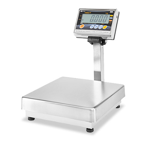
IWB − IWX Series (Overseas Use) Service Manual The First Edition Warning Read this manual thoroughly and do not perform installation, operation, maintenance, or inspection unless you fully understand all of the contents. Keep this manual in a safe place where you can refer to it easily while installing, operating, and carrying out maintenance or inspections.
Page 2
OUTLINE • Purpose of this manual This manual is used for reference at maintenance servicing of IWB or IWX series. • Relative manual For placing the product, mounting the display pole, setup mode and setup values, refer to the operation manual.
• The scale in this series is equipped with checking functions for the upper and lower limits of weight. • The main PCBs of the IWB series and IWX series are not identical but the common software is loaded. • The load cell has improved corrosion resistance by aluminizing process and the baked finish with acrylic resin.
Page 6
[Standard specification] External interface RS-232C 1ch for printer output or external buzzer [Option specification] Relay output using a contact BOX (AC adaptor is required for the IWB series) Option RS-232C connecting cable Contact BOX AC adaptor for the country specification IWB −...
Section 3. Appearance IWB-6 Rear of display Display Display fastening knob Loose Display pole Fasten Weigh platter Level vial Display pole Level adjusting foot Bracket pipe base IWB − IWX Series (Overseas Use) Service Manual Manual No. 0158A 6/68...
Page 8
IWB-30, IWX-30 Rear of display (The figure is for IWX.) Display Display fastening knob Display pole Loosen Weigh platter Fasten Display pole Level vial Level adjusting foot Bracket pipe base Bracket pipe IWB-150, IWX-150 Rear of display (The figure is Display for IWX.) Display...
Section 4. Operation Panel IWB Series ASIA, AUS specification IWX Series ASIA, AUS specification IWB − IWX Series (Overseas Use) Service Manual Manual No. 0158A 8/68...
Page 10
EU specification USA specification IWB − IWX Series (Overseas Use) Service Manual Manual No. 0158A 9/68...
Section 5. Outer Dimensions IWB-6 Unit: mm IWB/IWX-30 * The power cable is available only for IWX. A: Standard 348mm, AUS 678mm B: Standard 425mm, AUS 755mm Unit: mm IWB − IWX Series (Overseas Use) Service Manual Manual No. 0158A 10/68...
Page 12
IWB/IWX-150 * The power cable is available only for IWX. A: Standard 678mm, AUS 823mm B: Standard 755mm, AUS 900mm Unit: mm IWB − IWX Series (Overseas Use) Service Manual Manual No. 0158A 11/68...
Chapter 2. Test Mode The Test Mode is used for diagnosis and/or setting at maintenance service. Section 1. Operation The operation is explained in the followings on the ASIA/EU specification keys. For other country specification, read on the corresponding keys. Item 1.
C 8 ∼ 9 o p e ra tio n Key functions Function • ON/OFF switch of the IWB series. • ON/OFF switch of the IWX series. Circuit voltage +5V is normally supplied to the circuit board. • Value addition (when setting value) •...
Item 4. List of Modes Mode Contents Country No., Scale No., Zero point & Span adjustment Key check Display check 1 (simplified check) for multi-digit tube & LED all digit light-up. Display check 2 (detail check) for consecutive segment light-up for each digit of the multi- digit tube.
Page 16
1. When the country code is set, the measuring condition will function by the default data of the address 112∼115. Note 2. Do not change the data since they are determined in conformity to the approval certification conditions of each country. 3.
Page 17
Address 110A 110B 111A 111B Scale No Specifications Default data 30kg(0.01kg) 1/3000 Single range, baby scale specifications 300lb/150kg (1/3000) Multi interval 150lb/ 60kg (1/3000) Multi interval 60lb/ 30kg (1/3000) Multi interval 30lb/ 15kg (1/3000) Multi interval 15lb/ 6kg (1/3000) Multi interval Individual weighing capacity setup 1.
Page 18
Operation Display 4. Weight selection for Span adjustment Selection in the manner; 1/1.0→1/2.0→1/2.5→1/5.0 in kg unit of weighing capacity, 1/1.0→1/2.0→1/2.5→1/5.0 in lb unit of weighing capacity. Using weight as heavy as the weighing capacity in kg unit. Shift in the right order by the [ZERO(+)] key, or in the reverse order by the [TARE(−)] key.
Page 19
Operation Display 6. Span adjustment Load the selected weight on the weigh platter and press the [TARE(−)] key ON. Example: Pressing the [TARE(−)] key ON With the 30kg scale, selected weight: 1/1 in kg unit Loading 30kg weight, and 60000 + zero point 20000 makes 80000 counts.
Page 20
In the case of intentional fine tuning of the span 1. After the span adjustment, press the [COLUMN] key ON while A/D data is displayed. Tri− (trimming) (This can be done with the weight left loaded.) 2. Press the [ZERO(+)] key, and after Tri−U appears in the display, press the [ZERO(+)] key for appropriate times.
Item 7. C3 Mode ⋅⋅ Display Check 1 (Simplified check) The multi-digit fluorescent tubes for the IWB series, and the multi-digit fluorescent tubes and LED for the IWX series, all light up. Check for any unlit digit or overlapping lighting between digits (short-circuited).
Item 8. C4 Mode ⋅⋅ Display check 2 (Detail check) The digits of the multi-digit fluorescent tubes for the IWB series, and the multi-digit fluorescent tubes and LED for the IWX series, all light up for a segment after another. Check for any overlapping lighting between segments (short-circuited).
Item 10. C6 Mode ⋅⋅ RAM clear & E2ROM clear Operation Display 1. Test Mode start-up Press the [Display ON/OFF] key ON. Keep pressing the [ZERO(+)] key while the all segments are lighting. 2. Press the [ZERO(+)] key ON for five times. 3.
Item 11. C7 Mode ⋅⋅ Setup for measuring conditions The measuring conditions are determined to secure the scale certification conforming to each country by setting up the Country No. and Scale No. Note Each of the individual data can be changed in this mode. Select specification when using as the overseas indicator.
Page 25
Measurement Conditions Setup Table Address Weight Item Data 110A Decimal point 0: 0 1:0.0 position 2: 0.00 3:0.000 Minimum indication 0: 1 (At dual / Multi Interval 1 − 2 switching) 4: 2 (At dual / Multi Interval 2 − 5 − 10 switching) 8: 5 (At dual / Multi Interval 5 −...
Page 26
Address Weight Item Data 112A Starting range 0: ±1/50 of weighing capacity (±2%) 1: ±1/25 of weighing capacity (±4%) 2: ±1/10 of weighing capacity (±10%) 3: ±1/7.5 of weighing capacity (±13.3%) 4: ±1/6 of weighing capacity (±16.6%) 5: ±1/5 of weighing capacity (±20%) 6: ±1/4 of weighing capacity (±25%)
Item 12. C8 Mode ⋅⋅ E2ROM Data Readout Addresses 000 ∼ 127 can be read out in this mode. Operation Display 1. Test Mode start-up Press the [Display ON/OFF] key ON. Keep pressing the [ZERO(+)] key while the all segments are lighting.
Page 28
Address Data Contents Data Range Remark (default) 102A Selecting ON/OFF key function (bit 0) 0∼1 (F1) Set data in the Selecting preset automatic call-up function (bit 1) 0∼1 (F2) Registration Mode Selecting 16/24 digits printing (bit 2) 0∼1 (F3) (Operation Manual) Selecting date printing function (bit 3) 0∼1 (F4) 102B...
Item 13. C9 Mode -- PCB inspection (A/D check, I/F check) This mode is used for factory inspection. Not used for maintenance service. Operation Display 1. Test Mode start-up Press the [Display ON/OFF] key ON. Keep pressing the [ZERO(+)] key while the all segments are lighting.
Item 8. Approval seal ⋅ Masking seal ⋅ Ventilation seal This item explains the purpose of the 3 kinds of seal which are stuck on the display section at the rear case (case’ rear). Hexagonal bolt with flange Cover’ battery Cell cord inlet *IWX Power cord Seal’...
IWB display section block diagram I/F board (P-934-1) Main board P-936 * This board is of the standard but not the option. * The operation is guaranteed when using with the AC adaptor. (The IWX series is recommended.) Relay BOX A/D board P-933 LCD indicator tube output...
Item 2. Main Board P-936 Parts side of the main board (indicator tubes and tactile keys are mounted on the soldering side) RS232C AC adaptor I/F board AD board P-934 Battery BOX P-933A (Contact BOX) connector Memory Switch (1) SW1 Memory Switch Used for data re-writing at Test Mode initialization Used for storing the data in E2ROM (data rewriting) after changing country No., scale No.
Page 42
(4) Connector XJ3 AC adaptor input A to: AC adaptor Signal name Wire color B to: XJ3 PIN No. AC adaptor minus (GND) Black Dry battery minus Grey AC adaptor plus − − − Harness’ C2’ AC adaptor Fastener DC jack PH connector 4P (JST) Relation between AC adaptor (XJ3) and battery (XJ4) C-sized dry battery...
Page 43
(7) Program memory medium Mask ROM 256 KB (Re-writing or replacing is not permitted.) The IWB series P-936 and the IWX series P-935 are not compatible but using the same program. The program No. is J-535B (as of August, 2001) IWB −...
Page 44
(8) Power supply to logic circuit VCC and power supply to load cell VEX The C-sized battery voltage is once raised to 5.5V by the DC/DC converter of IC6 S-8321AMMP in the main board, and regulated to +5V in IC7 S-814AVC-BDO to supply the logic circuit power VCC and the load cell power VEX with a stable 5V.
Item 2. Main Board P-935 Parts side of the main board (fluorescent indicator tubes, LED and tactile keys are mounted on the soldering side) Power RS232C supply +5V Input/output input I/F board AD board P-934 (Contact P933A BOX) Memory Switch (1) SW1 Memory Switch Used for data re-writing at Test Mode initialization Used for storing the data in E2ROM (data re-writing) after changing country No., scale No.
Page 47
(6) Program memory medium Mask ROM 256 KB (Re-writing or replacing is not permitted.) The IWB series P-936 and the IWX series P-935 are not compatible but using the same program. The program No. is J-535B (as of August, 2001) (7) VEX (Load cell power supply +5V) SW ( switching) power supply contains noises at the level not influential to the logic circuit.
Item 3. I/F Board P-934-1 (option) (1) Major parts - Output:: 4 photo coupler NEC PS2501 - Input: photo coupler NEC PS2501 (2) Connector XJ1 ⋅ XJ2 ⋅ PC1 not mounted (3) Connector XJ3 - Used for direct connection with the main board. Refer to “connector XJ1”...
Item 4. SW Power Supply • SW (switching ) power supply is rated 100VAC−240VAC for input, and 5V 5W for output. • Maker: Densei Lambda • Type : ZWS5-5/J * The size to be mounted on the battery holder mounting position, is smaller than the SW power supply manufactured by COSEL.
Section 4. Common Matters to Electric Concern, A/D Circuit Board P-933 (1) Major parts • Amplifier circuit (LC8000) • A/D converter (AD7714YR) (2) Connector XJ1 Used for direct connection with the main board. Refer to “connector XJ2” (IWB) and XJ4 (IWX) of the main board for PIN No.
Chapter 4. Maintenance Section 1. Disassembling & Assembling the Display Section Case Disassembling (1) For IWB, remove the dry batteries or disconnect the AC adaptor. For IWX, disconnect the power plug from the outlet (2) Peel off the approval seal. (3) Remove the truss headed screw M4x15 for the seal.
Section 2. Replacing the Boards Item 1. IWB Series (1) Open the case in the same manner as described in the Section 1 above. (2) A/D Board P-933 While biting the open portion at the edge of the card spacer by using a pair of long-nose pliers, pull the board to disassemble from the connector of the Main board XJ2.
Item 2. IWX Series (1) Open the case in the same manner as described in the Section 1 above. (2) A/D Board P-933 While biting the open portion at the edge of the card spacer by a pair of long-nose pliers, pull the board to disassemble from the connector of the Main board XJ2.
Section 3. Replacing SW Power Supply of IWX Series The SW power supply (switching power supply) is located where the battery BOX is located for IWB series. The electrical specifications are same as that of the SW power supply for IWQ, but the unit size is smaller than that of IWQ by the reason of the room for mounting.
Page 56
Structural drawing for replacement in IWB-6 Hexagon-socket head bolt A M6×20 2 bolts Spring washer Four-corner limit bolt M4 15 4 b lt M4×15 4 bolts Hexagon-socket head bolt B M6×40 2 bolts Flat washer Load cell LC’AT-10’ Nylon clamp Spacer *The flat surface to be faced to the load cell.
Page 57
(7) When mounting the load cell, go through the procedures (4) – (6) in reverse order. The cell cable may rupture when forcefully pulled. Surface flaw may invite water intrusion and inner corrosion, resulting in fluctuated measurement and/or other Caution malfunctioning.
Page 58
Four-corner limit Platter Four-corner limit bolt bolt support M5 x 30 M5 x 30 Hexagon Spacer nut M5 Four-corner limit front Hexagon nut M5 Four-corner limit rear Load cell Lower limit Display pole side X pcs. of flat Lower limit bolt Base Spacer washers 5mm...
Check the battery and replace if necessary. 2. Low voltage of the battery. [IWB series] If AC adaptor is used, confirm the voltage is within 2.4−10VDC. Check conduction of the key using a multi- 3. ON/OFF key is defect.
Page 60
Problem Cause Measure Perform Test Mode C1 to check A/D value, if 5. Zero point and/or 3. Defect in A/D board or necessary, replace A/D board and load cell in weighing value the load cell. the order. fluctuate. Check +5V between R-W of A/D board XJ2 by 4.
Page 61
Reference Reference Relay input (IN1) does Refer to Setup Mode in the Operation Manual. not operate either. [IWB series] Check the main board connector XJ1 and I/F 2. Insufficient conductivity board connector XJ3 for contacts or at contacts. disconnection.
Section 2. RS-232C Input/Output Command Format Item 1. Input Command (Receiving Data) • Function execution command 1) Tare subtraction command (T command) 2) Zero adjustment command (Z command) 3) Preset call-up demanding command (P command) • Data demanding command 1) Scale data demanding 1 (08 command, instant one-time output after receiving) 2) Scale data demanding 2 (09 command, instant one-time output when transmission conditions meet, after receiving) * The input command is available only when “at the data demanding input”...
Page 64
Text layout 1 ( for function execution command) Receiving text Tare subtraction command Command Terminator Function: Performs actual tare weight subtraction. Character [SP] Code (54H) (20H) (0DH) (0AH) Zero adjustment command Command Terminator Function: Performs zero adjustment. Character [SP] Code (5AH) (20H) (0DH)
Page 65
Text layout 2 (for data output command) Receiving text Scale data demand 1 Command Terminator Function: Outputs one time instantly after receiving. Character Code (4FH) (38H) (0DH) (0AH) Scale data demand 2 Command Terminator Function: Outputs one time after receiving when verifying that Character the transmission condition Code...
Item 2. Output Format Five kinds of output format are available for selection at Setup Mode F10. 0: Format specialized for printer (default). 1: DAP-01 format 2: IWQ 1 format 3: MZ-7000 format 4: IWQ 2 format 5: IWQ 3 format 1) 0: Format specialized for printer Operation/function Line number...
Page 67
2) 1: DAP-01 format Weight value Scale Excess/appr Character Polarity Unit (Quantity number) status opriate/short Volume in 14 bytes byte H (48H): Weight exceeding upper limit. Output with floating point g (47H): Weight within the range. [Decimal point is fixed “.” L (4CH): Weight short to lower limit.
Page 68
4) 3: MZ-7000 format Upper Weight value Lower Preset Scale Pola- Character limit Index (Quantity Index limit Index status rity value number) value Volume in 32 bytes byte 30H: Weight value positive 31H: Weight value negative 30H: Weight value is stable. Indicates the position of decimal point 31H: Weight value is When the weight value is 123456;...
Page 69
6) 5: IWQ3 format Under Right Left Weight Character Index Filler cursor cursor cursor (Display 1) Volume in 32 bytes byte Cursor indication status 30H∼3FH Indicates the position of decimal point When the weight value is 123456; Cursor indication status 01:12345.6 30H∼3FH 02:1234.56...
Page 70
Design and specifications are subject to change without notice. 44 SANNO-CHO, SHOGOIN, SAKYO-KU KYOTO, 606-8392 JAPAN PHONE: 81-75-771-4141 FACSIMILE: 81-75-751-1634 URL: http://www.ishida.co.jp...
Need help?
Do you have a question about the IWB Series and is the answer not in the manual?
Questions and answers