Advertisement
Quick Links
Service Manual
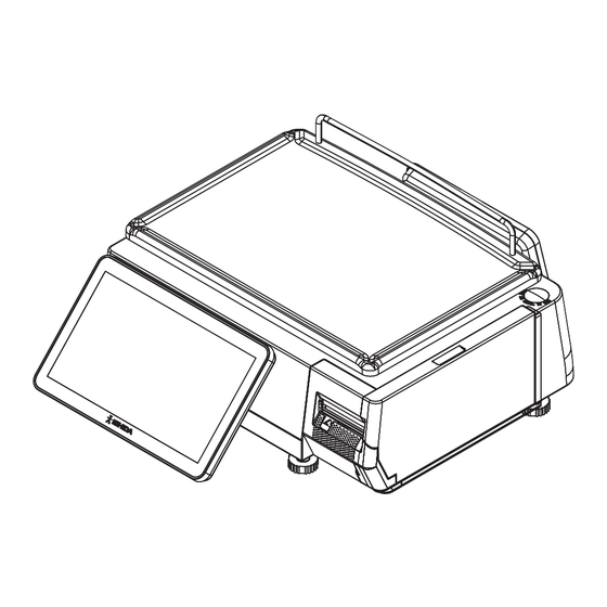
Bench type
• Do not carry out installation, operation, service or maintenance until the contents of this manual are
thoroughly understood.
• Keep this manual available at all times so that it can be referred to as necessary for the purposes of
installation, operation, service, and maintenance.
The use of this manual is for our service personnel and persons authorized to carry out maintenance
work of this machine.
The use of this manual by any person other than the above is strictly prohibited.
UNI-8
IMPORTANT
Pole type
1st Edition
Hanging type
Dec 2023
Advertisement

Subscribe to Our Youtube Channel
Related Manuals for ISHIDA UNI-8


Summary of Contents for ISHIDA UNI-8
- Page 1 UNI-8 Service Manual 1st Edition Bench type Pole type Hanging type • Do not carry out installation, operation, service or maintenance until the contents of this manual are thoroughly understood. • Keep this manual available at all times so that it can be referred to as necessary for the purposes of installation, operation, service, and maintenance.
- Page 2 Introduction Revision History Version Date Description Dec, 2023 1st edition ISHIDA Co., Ltd., 2023 No part of this manual may be reproduced in any form, by mimeograph or any other means, without written permission of Ishida.
- Page 3 Introduction Introduction Purpose of this Manual The purpose of this manual is as reference material for the delivery, installation, repair and maintenance of this machine. Target Readers This manual has been written specifically for use by our service personnel. The use of this manual by any person 0ther than above is strictly prohibited. Signal Words The signal words shown in this manual are separated into two stages depending on the level of danger or the seriousness of potential injury.
- Page 4 Introduction Precautions for handling • Do not allow water or any liquids to come into contact with the machine. Doing so may result in fire or cause the machine to break down. • Do not drop or apply a strong shock to the machine.
- Page 5 Introduction Precautions wen using Cleaning Fluids • Use a soft cloth and a neutral detergent to clean the machine. Do not use thinner, benzene, etc. Doing so may damage the original safety functions. For some parts, use cleaning fluid (isopropyl alcohol). •...
- Page 6 Introduction Precautions for installation • Do not install the machine in the following types of places: Places subject to high Places subject to excessive Places subject to a lot of dust temperatures or high humidity vibration or unstable or dirt foundations Places exposed to direct Places with large voltage...
- Page 7 Introduction Table of Contents Revision History ....................II Purpose of this Manual ................... III Target Readers....................III Signal Words ....................III Precautions for handling .................IV Precautions wen using Cleaning Fluids ............V Precautions for installation ................VI Table of Contents ...................VII Chapter 1 Overview ....................1-1 1.1 External Dimentions ................
- Page 8 Introduction 3.3.3 Thermal Head ................3-9 3.3.4 Printer Unit ..................3-11 3.3.5 PS-067 A/D Board ............... 3-12 3.3.6 PS-096C Printer Board ..............3-12 3.3.7 PS-100 Main Board ................3-12 3.3.8 PS-097 Power Board ..............3-13 3.3.9 Power Supply ................3-13 3.3.10 Load Cell ................... 3-14 Chapter 4 Electric Components ................
- Page 9 Introduction 5.5.1 Display key .................. 5-13 5.5.2 Function key ................5-14 5.6 Data storage..................5-15 5.6.1 Total ADD..................5-15 5.6.2 Total PROC.................. 5-16 5.6.3 Transaction .................. 5-17 5.6.4 Strage ..................5-18 5.7 Preset report ..................5-19 5.7.1 Daily ..................... 5-19 5.8 PLU overwrite..................
- Page 10 Introduction 5.18.7 Self .................... 5-45 5.18.8 Log ..................... 5-46 5.18.9 Talon ..................5-47 5.18.10 Auto PLU ................. 5-48 5.18.11 Scanner ................... 5-49 5.19 Error process..................5-50 5.19.1 Issue ..................5-50 5.19.2 Call .................... 5-51 5.19.3 Common ..................5-52 5.20 Error log ....................5-53 5.20.1 Display ..................
- Page 11 Introduction 6.7 Calibration ..................... 6-14 6.7.1 Procedure for adjusting scale (span) ........... 6-15 6.8 Machine type ..................6-17 6.8.1 Detail ................... 6-18 6.9 Download ....................6-19 6.9.1 Main ..................... 6-19 6.9.2 Sub APP..................6-20 6.9.3 Sub boot ..................6-21 6.10 Option check ..................
- Page 12 Introduction Memo...
- Page 13 Chapter 1 Overview Chapter 1 Overview 1.1 External Dimentions 1.1.1 Bench type 482 535 (unit : mm)
- Page 14 Chapter 1 Overview 1.1.2 Pole type 470 ~ 525 (unit : mm)
- Page 15 Chapter 1 Overview 1.1.3 Hanging type (unit : mm)
- Page 16 Chapter 1 Overview 1.2 Specifications 1.2.1 Weighing unit Items Descriptions Weighting accuracy 1/3000 (Precision class based on new measurement standards in Japan: Class III) 15 kg specification: 0 to 6 kg / 0.002 kg, Weighing capacity 6 to 15 kg / 0.005 kg, Scale interval 0 to 15 kg / 0.005kg(Single Range) 30 kg specification:...
- Page 17 Chapter 1 Overview 1.2.4 Others Items Descriptions Power supply For EU: 220 – 240 VAC/ 0.5A For South Africa: 220 – 240 VAC /0.5A For USA: 100 – 120 VAC /1.0A For Argentina: 220 – 240 VAC /0.5A Use conditions Temperature: -5 to 40°C Humidity: 20 to 85%, Non-condensing Input/ Output...
- Page 18 Chapter 1 Overview 1.3 Power supply • It is strongly advised that the following safety measures must be observed to ensure the safe operation of the machine: • Read precaution instructions described in this manual before connecting the power plug into the outlet.
- Page 19 Chapter 2 Mechanical hardware Chapter 2 Mechanical hardware 2.1 Bench type 2.1.1 Exploded view...
- Page 20 Chapter 2 Mechanical hardware 2.2 Pole type 2.2.1 Exploded view...
- Page 21 Chapter 2 Mechanical hardware 2.3 Hanging type 2.3.1 Exploded view...
- Page 22 Chapter 2 Mechanical hardware Memo...
- Page 23 Chapter 3 Machine disassembly Chapter 3 Machine disassembly 3.1 For each type Make sure to unplug the power cord from the wall outlet before starting the disassembly work. The procedure of this section is based on that of Bench Type. For the Customer Display and Operation Display of Hanging Type, refer to the section3.3 Hanging Type.
- Page 24 Capter 3 Machihe disassembly 6. Remove the case cover. 5. Pull up the front side of the case cover to disengage. * Reverse this procedure for assembly. 3.1.2 Support and Load Cell 2. Remove the support. 1. Remove the two hex screws (5 mm).
- Page 25 Chapter 3 Machine disassembly 5. Remove the five hex screws (4 mm). 6. Pull PS-067 straight up and unplug the connector on the back side. 7. Detach the load cell unit.
- Page 26 Capter 3 Machihe disassembly 8. Remove the two hex screws. When replacing the load cell, remove the solder. * Reverse this procedure for assembly.
- Page 27 Chapter 3 Machine disassembly 3.2 Pole type Make sure to unplug the power cord from the wall outlet before starting the disassembly work. 3.2.1 Pole Unit 1. Detach the platter. 2. Remove the three screws. Platter 4. Unplug the connector. 3.
- Page 28 Capter 3 Machihe disassembly 6. Remove the two screws. 7. Detach the cover. 8. Remove the four screws. 9. Open the cover. For the TOUCH PANEL PCB and DISPLAY, refer to the chapter 4 Electric Components. * Reverse this procedure for assembly.
- Page 29 Chapter 3 Machine disassembly 3.3 Hanging type Make sure to unplug the power cord from the wall outlet before starting the disassembly work. 3.3.1 Case Cover 2. Remove the four hinge nuts and 1. Remove two housing seal screws. remove the side panels. 4.
- Page 30 Capter 3 Machihe disassembly 8. Remove the screw and remove 7. Remove the three screws. front and rear covers. 3.3.2 PS-105 Module Board 2. Unplug the connectors. 1. Cut off the cable tie. 3. Cut off the cable tie. Rear Display Connecter Position...
- Page 31 Chapter 3 Machine disassembly 4. Unplug the connectors. Front Display Connecter Position 6. Remove the two screws and 5. Unplug the connectors. detach PS-105 module board. 3.3.3 Thermal Head 1. Cut off the two cable ties. 2. Unplug the connectors.
- Page 32 Capter 3 Machihe disassembly 4. Cut off the two cable ties. 3. Cut off the cable tie. 6. Unplug the connecter and remove 5. Pull out the print connection cable. Thermal Head. 7. Pull out the print connection cable. 3-10...
- Page 33 Chapter 3 Machine disassembly 3.3.4 Printer Unit 1. Remove the three screws and detach the printer unit. 2. Remove the screw and detach the 3. Remove the screw and detach the peel sensor assembly. tie rod assembly. 3-11...
- Page 34 Capter 3 Machihe disassembly 3.3.5 PS-067 A/D Board 1. Pull PS-067 straight up and unplug When replacing the load cell, remove the connector on the back side. the solder. 3.3.6 PS-096C Printer Board 2. Remove the four screws and 1. Unplug the connectors. remove PS-096C Printer Board.
- Page 35 Chapter 3 Machine disassembly 3.3.8 PS-097 Power Board 2. Remove the four screws and 1. Unplug the connectors. remove PS-097 Power Board. 3.3.9 Power Supply 2. Cut off the cable tie. 1. Remove the two screws and remove the support plate. 2.
- Page 36 Capter 3 Machihe disassembly 3.3.10 Load Cell 2. Remove the two screws and 1. Remove the three screws. detach the load cell unit. 4. Remove the sensor gasket. 3. Remove the two screws and remove the bracket. 6. Remove the sensor gasket. 5.
- Page 37 Chapter 3 Machine disassembly 7. Detach the load cell. * Reverse this procedure for assembly. 3-15...
- Page 38 Capter 3 Machihe disassembly Memo 3-16...
- Page 39 Chapter 4 Electric Components Chapter 4 Electric Components 4.1 Disassembly procedure Make sure to unplug the power cord from the wall outlet before starting the disassembly work. 4.1.1 Printer Board PS-096C 1. Unplug the eight connectors. 2. Detach the printer unit. 3.
- Page 40 Capter 4 Electric Components 4.1.2 Module Board PS-105 1. Unplug the one connector. 2. Remove the two screws. 3. Remove the Module Board. * Reverse this procedure for assembly.
- Page 41 Chapter 4 Electric Components 4.1.3 Main Board PC-100 2. Remove the four screws. 1. Unplug the seven connectors. 3. Remove the main board. * Reverse this procedure for assembly.
- Page 42 Capter 4 Electric Components 4.1.4 Display Board PS-098 1. Unplug the one connector. 2. Remove the two screws. 3. Remove the display board. * Reverse this procedure for assembly.
- Page 43 Chapter 4 Electric Components 4.1.5 Power Board PS-097 2. Remove the four screws. 1. Unplug the two connectors. 3. Remove the power board. * Reverse this procedure for assembly.
- Page 44 Capter 4 Electric Components 4.1.6 Main Display and Touch Panel Board 1. Remove the two screws. 2. Cut the tie and untie the cords. 3. Remove the four screws. 4. Remove the cover. 5. Unplug the two connectors. 6. Pull up the stopper and unplug the flat cable.
- Page 45 Chapter 4 Electric Components 7. Remove the three screws. 8. Remove the touch panel board. Be careful not to lose the plastic spacers. NOTE Double-sided tape is required for maintenance. NOTE 9. Remove the seven screws. 10. Remove the plate. * Reverse this procedure for assembly.
- Page 46 Capter 4 Electric Components 4.1.7 Customer Display 1. Unplug the one connector. 2. Remove the seven screws. 3. Remove the plate.
- Page 47 Chapter 4 Electric Components 4.1.8 Thermal head 2. While holding the plate, remove the 1. Open the side cover and remove the cassette cover. two screws. 3. Push up the plate. 4. Pull out the thermal head and unplug the connector.
- Page 48 Capter 4 Electric Components 4.2 Electrical signals 4.2.1 PS-067 Signal Name Direction Opposite Side <- Load Cell <- Signal Name Direction Opposite Side Not Connected XIN_2.5MHz <- RESET <- SCLK <- Not Connected PS-096C Not Connectted DRDY -> Not Connected 4-10...
- Page 49 Chapter 4 Electric Components 4.2.2 PS-096C Signal Name Direction Opposite Side Not Connected Not Connected Not Connected VBUS PS-100 USB <-> <-> Not Connected Signal Name Direction Opposite Side PS-097 4-11...
- Page 50 Capter 4 Electric Components Signal Name Direction Opposite Side -> Cash Drawer Signal Name Direction Opposite Side SPAN_SW <- PS-063, PS-055 Signal Name Direction Opposite Side Not Connected XIN_2.5MHz -> RESET -> SCLK -> Not Connected PS-067 Not Connectted DRDY <- Not Connected Signal Name...
- Page 51 Chapter 4 Electric Components Signal Name Direction Opposite Side Not Connected Not Connected -> <- <- Thermal Head STB2 -> Not Connected XJ10 Signal Name Direction Opposite Side 3.3V VCC for LED -> Label Sensor Sensor In <- Not Connected XJ11 Signal Name Direction...
- Page 52 Capter 4 Electric Components XJ13 Signal Name Direction Opposite Side OUT1 -> OUT2 -> Cutter Unit Sensor In <- XJ14 Signal Name Direction Opposite Side 3.3V Sensor In <- Cutter Set Sensor 4-14...
- Page 53 Chapter 4 Electric Components 4.2.3 PS-097 Signal Name Direction Opposite Side <- <- Switch Power Supply <- <- Signal Name Direction Opposite Side -> -> PS-100 -> -> Signal Name Direction Opposite Side -> -> PS-100 -> -> 4-15...
- Page 54 Capter 4 Electric Components Signal Name Direction Opposite Side -> -> Signal Name Direction Opposite Side -> -> Signal Name Direction Opposite Side -> -> Signal Name Direction Opposite Side -> -> -> PS-096C -> -> -> 4-16...
- Page 55 Chapter 5 Setup Mode Chapter 5 Setup Mode 5.1 Setup menu 5.1.1 Startup 1. Turn on power. Power SW 2. Press button at the upper right side of ccreen. Press [SETUP] and [LOGIN] button, then input Password "495344" using numerical keys, and press [SET] button.
- Page 56 Capter 5 Setup Mode Before log in Login screens Common operating buttons • Return to Menu. • Return to previous page. • Go to next page. • Input [.].
- Page 57 Chapter 5 Setup Mode 5.2 Machine No. setting 5.2.1 Basic 5.2.1.1 Alone Menu name Specification MACHINE No. Enter the machine number. Input range: 1 to 99 NETWORK No. Enter the network number. Input range: 1 to 9 MACHINE SET Select one of the stand-alone, master or satellite machines. ALONE / MASTER / SAT.
- Page 58 Capter 5 Setup Mode 5.2.1.2 Master Menu name Specification MASTER PORT Enter the master port number. Input range: 0 to 65535 SAT. PORT Enter the satellite port number. Input range: 0 to 65535 PLU SYNC. Enter whether or not to sync with the PLU. YES / No Enabled only when you access above menus after logging in with the service password.
- Page 59 Chapter 5 Setup Mode 5.2.1.3 SAT. Menu name Specification MASTER IP Enter the IP address of master. ADDRESS Input range: “0.0.0.0” to “255.255.255.255” COMMUNICATION Select mode of communication online or offline. MODE OFFLINE / ONLINE PLU REFERENCE Select mode of PLU reference setting. LOCAL / MASTER PING TO MAS.
- Page 60 Capter 5 Setup Mode 5.2.2 IP address Menu name Specification IP ADDRESS Enter the IP address. Input range: “0.0.0.0” to “255.255.255.255” SUBNET MASK Enter the subnet mask. Input range: “0.0.0.0” to “255.255.255.255” DEFAULT Enter the default gateway. GATEWAY Input range: “0.0.0.0” to “255.255.255.255” DNS SERVER1 Enter the IP address of Primary DNS server.
- Page 61 Chapter 5 Setup Mode 5.2.3 PC COM Menu name Specification PC IP ADDRESS Enter the PC's IP address. Input range: “0.0.0.0” to “255.255.255.255” PC PORT No. Enter the PC's port number. Input range: 0 to 65535 COM CHECK Enter the command check period. PERIOD (SEC) Input range: 0 or 30 to 9999 COM CHECK TIME...
- Page 62 Capter 5 Setup Mode Menu name Specification PROD. TRAN. SEND Enter whether or not to perform transmission of Prod. Transaction. NO SEND / SEND SALE TRAN. SEND Enter whether or not to perform transmission of Sale Transaction. NO SEND / SEND PING TO PC Ping the PC.
- Page 63 Chapter 5 Setup Mode 5.2.4 WiFi Menu name Specification SECURITY / Select the method of securi t y/authenticati o n/encryption. AUTHENTICATION NONE / WEP64 / WEP128 / WEP64 Shared Key / WEP128 ShKey / / ENCRYPTION WPA PSK TKIP / WPA PSK CCMP / WPA2 PSK TKIP / WPA2 PSK CCMP SSID (WIRELESS Enter the SSID.
- Page 64 Send PING to the set cl oud server (When the cloud function is not in use, the option is grayed out). Menu name Specification VNC SERVICE Select whether or not to use the VNC service. After startup, you can connect the Uni-8 and perform remote operation using the VNC Viewer. STOP / START 5-10...
- Page 65 Chapter 5 Setup Mode 5.3 Sales mode Menu name Specification SALES MODE Select the sales mode. 5-11...
- Page 66 Capter 5 Setup Mode 5.4 Password 5.4.1 Operate Menu name Specification PASSWORD Enter password in six digits. Logging in by this password will release the menu operation prohibited status. MENU NAME Display the menu name. Both USE and NO USE for SALES are grayed out because SALES cannot be locked with the password.
- Page 67 Chapter 5 Setup Mode 5.5 Key lock 5.5.1 Display key Menu name Specification PASSWORD Enter the password in six digits. Normally in PRODUCTION screen, enter this password and press KEY LOCK FUNCTION to release the input prohibited status. KEY NAME Display measurement menu on normal mode screen.
- Page 68 Capter 5 Setup Mode 5.5.2 Function key Menu name Specification PASSWORD Enter the password in six digits. Normally in PRODUCTION screen, enter this password and press KEY LOCK FUNCTION to release the input prohibited status. KEY NAME Display the function key name. Not displayed WEIGHT/PRICE when [OCEANIA] is selected on COUNTRY menu.
- Page 69 Chapter 5 Setup Mode 5.6 Data storage 5.6.1 Total ADD. Menu name Specification MENU NAME Display menu name. SELECT Select whether or not to add. NON ADD / ADD TOTAL PROC. / TRANSACTION / STORAGE tabs are displayed only when you access above menus after logging in with service password.
- Page 70 Capter 5 Setup Mode 5.6.2 Total PROC. Menu name Specification FIX PRICE ITEM Select the addition weight of fixed-price items. ADD WEIGHT FIX WEIGHT / REAL WEIGHT ITEM COUNT Select to count items. SELECT MULTIPLY / DETAILS 5-16...
- Page 71 Chapter 5 Setup Mode 5.6.3 Transaction Menu name Specification PROD. Select whether or not to add the product transaction. TRANSACTION NON ADD / ADD TRANS. MEM. Select between stopping or overwrit i ng the transaction addition at full FULL memory condition. STOP / OVERWRITE SALES Select whether or not to add the sales transaction.
- Page 72 Capter 5 Setup Mode 5.6.4 Strage Menu name Specification TRANSACTION Select where to save the transaction. BUILT-IN / CARD / USB 5-18...
- Page 73 Chapter 5 Setup Mode 5.7 Preset report 5.7.1 Daily Menu name Specification TOTAL REPORT Display the report menu name. NAME SELECT Select whether or not to print the report. NO PRINT / PRINT (All tabs have the same operations so their explanations are omitted here.) 5-19...
- Page 74 Capter 5 Setup Mode 5.8 PLU overwrite Menu name Specification PLU MASTER LIST Display the PLU master list. SELECT Select whether or not to overwrite the value. YES / NO 5-20...
- Page 75 Chapter 5 Setup Mode 5.9 PLU initial data 5.9.1 Sale 1 Menu name Specification (Each item) Enter the initial val ue to newly create the PLU master. (All tabs have the same operations so their explanations are omitted here.) 5-21...
- Page 76 Capter 5 Setup Mode 5.10 PLU update Menu name Specification START No. Enter the start number of the batch change range. Input range: 1 to 99999999 END No. Enter the end number of the batch change range. Input range: 1 to 99999999 UNIT PRICE No.
- Page 77 Chapter 5 Setup Mode 5.11 Receipt setting 5.11.1 Title Menu name Specification HEADER TEXT Enter text of header. Press button to open editor screen. FOOTER TEXT Enter text of footer. Press button to open editor screen. HEADER LOGO Enter logo of header. Press button to open image list screen.
- Page 78 Capter 5 Setup Mode 5.11.2 Barcode Menu name Specification POS FLAG Enter the POS flag. Input range: 00 to 99 POS CODE TYPE Select the POS code type. 1: EAN / UPC13 / 2: EAN / UPC 8 / 3: 10 DIGITS 13 / 4: 5 DIGITS 8 / 5: GS1 RECEIPT CODE Enter the receipt code.
- Page 79 Chapter 5 Setup Mode 5.11.3 Receipt No. Menu name Specification RECEIPT START Enter the receipt starting number. Input range: 1 to 999999 DAILY TOTAL Enter the daily total auto clear setting. AUTO CLEAR NO / YES RECEIPT END No. Enter the receipt ending number. Input range: 1 to 999999 RECEIPT COUNT Enter the receipt counting number.
- Page 80 Capter 5 Setup Mode 5.12 Cassete Menu name Specification PRINTER Display only PRN 1. PLU No. Enter the PLU number to use for test printing. Input range: 0 to 99999999 For 0, print the checker label. LABEL W. Display the format width of label. LABEL L.
- Page 81 Chapter 5 Setup Mode Menu name Specification 2nd FMT No. Enter the format to be used in the second label printing. Input range: 0 to 999 SUBTTL FMTno. Enter the subtotal format number. Input range: 0 to 999 SALES MODE Select the sales mode.
- Page 82 Capter 5 Setup Mode 5.13 Label spec Menu name Specification LABEL TYPE Select the label type. 0: RECEIPT / 1: 130LA-1 / 3: 150LA-1 PRINT DENSITY Enter the print densit y control of black character. Input range: 0 to 9 RED DENSITY Enter the print densit y control of red character.
- Page 83 Chapter 5 Setup Mode 5.14 Label format 5.14.1 Detail (basic) Menu name Specification FORMAT NAME Press button to open the format name edit screen. Press "<" and ">" located at both sides of the box to select the next (or previous) format master.
- Page 84 Capter 5 Setup Mode Menu name Specification Y-AXIS Display the Y axis of selected unit. The axis is moved by entering numerical number. FEED Feed the label. PRINT Perform test printing by the format called and the item information set by PLU number.
- Page 85 Chapter 5 Setup Mode 5.14.2 Detail (unit) Menu name Specification FORMAT NAME Press button to open the format name edit screen. Press "<" and ">" located at both sides of the box to select the next (or previous) format master. STRING EDIT Open the format string edit screen.
- Page 86 Capter 5 Setup Mode 5.14.3 Detail (preview) Menu name Specification DETAILED IMAGE Select the whole image or detailed image. /WHOLE IMAGE FEED Feed the label. PRINT Perform test printing by the format called and the item information set by PLU number. ←↑→↓...
- Page 87 Chapter 5 Setup Mode 5.15 Barcode 5.15.1 POS flag Menu name Specification EAN/UPC 13 Enter the NON-PLU 13 digits. Input range: 00 to 99 EAN/UPC 8 Enter the NON-PLU 13 digits. Input range: 0 to 9 10 DIGITS 13 Enter the PLU 13 digits. Input range: 00 to 99 5 DIGITS 8 Enter the PLU 8 digits.
- Page 88 Capter 5 Setup Mode 5.15.2 POS code Menu name Specification POS CODE TYPE Select the POS code type. 1: EAN/UPC13 2: EAN/UPC 8/3:10 DIGITS 13/4:5DIGITS 8/5:GS1 6:GS1 ST/7:GS1 STO/8:GS1 LI MITED/9:GS1 EXPANDED/10: ITF Select the POS code type. 1: EAN/UPC13 2: EAN/UPC 8/3:10 DIGITS 13/4:5DIGITS 8/5:GS1 6:GS1 ST/7:GS1 STO/8:GS1 LI MITED/9:GS1 EXPANDED/10: ITF GS1 EXP FORMAT Select the GS1 EXP format.
- Page 89 Chapter 5 Setup Mode 5.15.3 Item code Menu name Specification DEPARTMENT No. Execute the digit set of department number. DIGIT SET Press numerical number to switch the selection. Press numerical number in series. (e.g. The combination of "1" and "3" cannot be selected. The combination of "1", "2"...
- Page 90 Capter 5 Setup Mode 5.16 Custom barcode 5.16.1 Basic Menu name Specification Enter the item number to be used for the preview. Input range: 1 to 99999999 Other tabs also have the same function. FORMAT Input range: 1 to 999 Other tabs also have the same function.
- Page 91 Chapter 5 Setup Mode 5.16.2 Preview Menu name Specification The combined-barcode preview is displayed only. 5-37...
- Page 92 Capter 5 Setup Mode 5.17 Menu title 5.17.1 Operate Menu name Specification DEFAULT NAME Display the menu name before editing. Press button to select the menu name. NEW NAME Display the menu name after editing. Press button to select the menu name. EDIT Transfer to the edit screen of the selected menu name.
- Page 93 Chapter 5 Setup Mode 5.18 Operation setting 5.18.1 Call1 Menu name Specification FIND PLU Select how to search PLU. START CHAR. / LINE1 / LINE2 / ALL / START LINE2 OPEN PLU Select whether or not to open the PLU. YES / NO PROMO Select whether or not to confirm a sales promotion.
- Page 94 Capter 5 Setup Mode 5.18.2 Production Menu name Specification WEIGHED Select whether or not to check the weight of weighed items. ITEMS'WEIGHT NO / YES RANGES CHECK TARE SELECT Select the tare. 1st TARE / 2nd TARE FIX PRICE AUTO Select whether or not to check and print the weight of fixed-price PRN (WEIGHT) product.
- Page 95 Chapter 5 Setup Mode 5.18.3 Timer Menu name Specification REGISTRATION Enter the registration timer. TIMER Input range: 0 to 9999 (seconds) SUB-TOTAL TIMER Enter the time to return to the previous screen while no operation in the subtotal mode. Input range: 0 to 9999 (seconds) PRINTING Enter the time to return to the previous screen while no operation after TERM.TIMER...
- Page 96 Capter 5 Setup Mode 5.18.4 CR1 Menu name Specification VAT PRINT Select whether or not to print the vat printing. NO / YES AUTO MODE Select the automatic operation mode. OPERATION CONTINUE / EACH DRAWER OPEN Select the drawer operation to open. PRN START / PRN END DRAWER 0 OPEN Select whether or not to operate the drawer 0 open operation.
- Page 97 Chapter 5 Setup Mode 5.18.5 CR2 Menu name Specification SUBTT-FOR Select whether or not to set the items of subtotal for discount. DISCOUNT ITEM NO / YES TENDER AMOUNT Select the operation mode of tender amount input. INPUT AUTO / MANUAL RECEIPT TARE Select whether or not to pr int with the receipt tare.
- Page 98 Capter 5 Setup Mode 5.18.6 Input Menu name Specification INPUT Select the type for input. TYPE1 / TYPE2 TARE RESET Select mode of tare resetting. MANUAL / AUTO CALENDAR INPUT NO / YES DISTRIBUTION INPUT ADD / DELETE + ADD 5-44...
- Page 99 Chapter 5 Setup Mode 5.18.7 Self Menu name Specification PRINT MODE Select mode for printing. MANUAL / AUTO SEARCH TYPE Select the searching type. PRESET / PLU AUTO PRINT Enter the time to set the auto print timing. TIMING (msec) Input range: 0 to 5000 5-45...
- Page 100 Capter 5 Setup Mode 5.18.8 Log Menu name Specification OPERATOR LOG Select whether or not to be used to login for the operator. IN OUT NO / YES 5-46...
- Page 101 Chapter 5 Setup Mode 5.18.9 Talon Menu name Specification TALON Select the talon. DISABLE / ENABLE TALON Enter the time to set the talon printing. PRINT(msec) Input range: 0 to 3000 TALON ORDER Select the talon. BEFORE / AFTER 5-47...
- Page 102 Capter 5 Setup Mode 5.18.10 Auto PLU Menu name Specification AUTO PLU CALL Select the type for input. TYPE1 / TYPE2 AUTO PLU TIMER Select mode of tare resetting. (msec) MANUAL / AUTO 5-48...
- Page 103 Chapter 5 Setup Mode 5.18.11 Scanner Menu name Specification ITEM CODE Enter digits of item code. DIGITS Input range: 4 to 5 5-49...
- Page 104 Capter 5 Setup Mode 5.19 Error process 5.19.1 Issue Menu name Specification PRINTING AT 0 Select the action of printing at 0. PRICE BARCODE=0 No PRICE / No BAR.P RICE=0 / No BAR. No PRICE The currency unit depends on the country master. DISPLAY ERROR: Select whether or not to display the error message when the tare TARE WEIGHT...
- Page 105 Chapter 5 Setup Mode 5.19.2 Call Menu name Specification NO POS CODE Select the action when the POS code is not set. SET ERROR NO ERROR DISPLAY / NO LABEL PRINT / NO BAR PRINT EXTRA MSG. 1 NO / YES INGREDIENT NO / YES EXTRA MSG.
- Page 106 Capter 5 Setup Mode 5.19.3 Common Menu name Specification DAMAGED Select how to set the error message of damaged thermal head. THERMAL HEAD ON TIME MSG / CONTINUOUS MSG / NO MESSAGE ERROR DISPLAY PRINTER COMMS DATA OUTPUT NO / YES OUTPUT LOGGING TYPE LOG1 / LOG2...
- Page 107 Chapter 5 Setup Mode 5.20 Error log 5.20.1 Display Menu name Specification LOG LEVEL Select the error log level to be displayed on the list. ONLY ERR. / ERR. +OPE. DELETE Delete the error log. The DELETE CHECK dialog appears to ask whether to delete the error log.
- Page 108 Capter 5 Setup Mode 5.20.2 SAVE Menu name Specification OPERATION LOG SAVE NO / YES COMMUNICATION LOG SAVE NO / YES 5-54...
- Page 109 Chapter 5 Setup Mode 5.21 Tranceability Menu name Specification TRACEABILITY Select the traceability type. TYPE TYPE1 / TYPE2 (TYPE1 is simple traceability.) TRACEABILITY Select whether or not to add the traceability total. TOTAL NO / YES TRACE. DATA Select the manual or auto deletion of traceability data. DELETE MANUAL / AUTO TRACEABILITY...
- Page 110 Capter 5 Setup Mode 5.22 Dual currency Menu name Specification EXCH. RATE Enter the exchange ra te of the second currency. Input range: 0 to 99999999 EXCH. RATE DEC. Enter the decimal point position of the exchange rate of the second PNT.
- Page 111 Chapter 5 Setup Mode 5.23 Price rounding Menu name Specification TAX ROUNDING Select the tax rounding type. 4/5 / 05 / UP PRICE ROUNDING Select the price rounding type. 4/5 / 05 DISCOUNT Select the discount rounding type. ROUNDING DOWN / 4/5 / UP SUB-TOTAL PRICE Select the subtotal price rounding type.
- Page 112 Capter 5 Setup Mode 5.24 Frequent sopper Menu name Specification BARCODE PRICE Select the barcode price type. TYPE NORMAL / MARKDOWN LOGO IMAGE 1 Enter the logo image 1 number. Input range: 0 to 999 PRICE DISP NO / YES 5-58...
- Page 113 Chapter 5 Setup Mode 5.25 Data distribution 5.25.1 Machine Menu name Specification MACHINE No. Enter the machine number. Input range: 0 to 99 IP ADDRESS Enter the IP address. Input range: “0.0.0.0” to “255.255.255.255” DELETE Delete the selected line. 5-59...
- Page 114 Capter 5 Setup Mode 5.25.2 Data Menu name Specification DATA NAME Display the data name. SELECT Select whether or not to distribute the master. YES / NO ALL SELECT Select all lines. 5-60...
- Page 115 Chapter 5 Setup Mode 5.26 Tax Menu name Specification TAX TYPE Select tax type. EXCLUDED / INCLUDED / EXEMPT TAX RATE Enter the tax rate. Input range: 0.00 to 99.99 (%) 5-61...
- Page 116 Capter 5 Setup Mode 5.27 Country Menu name Specification COUNTRY Select the country. Enter 951753 and press PLU to enable this function. Press COUNTRY button to open the list and select the country. LANGUAGE Enter the first to third language. Press button to open the list and select the language.
- Page 117 Chapter 5 Setup Mode 5.28 File save/Load 5.28.1 USB>Scale Menu name Specification INPUT SOURCE Display the name of the input source. INPUT SELECT Open the FILE SAVE/LOAD IN SELECT screen. The input source is listed only when the files are saved on the USB flash drive.
- Page 118 Capter 5 Setup Mode 5.28.2 Scale>USB Menu name Specification OUT SOURCE Display the name of the output source. OUTPUT SELECT Open the FILE SAVE/LOAD OUT SELECT screen. SET: Enter the output source. EDIT: Edit the name of the output source. ALL SEL.
- Page 119 Chapter 5 Setup Mode 5.28.3 USB data DEL. Menu name Specification DELETE SELECT Display the name of the deletion source. MASTER NAME Display the master name of the file in the folder of USB memory specified as “Deletion destination”. ALL SEL. Switch between “All items selected”...
- Page 120 Capter 5 Setup Mode 5.28.4 Scale INIT. Menu name Specification DATA Display the master name. Press button to change the selection. MASTER NAME Display the master name in the scale. Line selection/deselection is available. NUMBER Display the data Number of the master inside the scale. MEMORY SPACE Display the memory space inside the scale in kilobyte (kB).
- Page 121 Chapter 5 Setup Mode Memo 5-67...
- Page 122 Chapter 6 Adjust Mode Chapter 6 Adjust Mode 6.1 Adjust mode menu 6.1.1 Startup 1. Turn on power. Power SW 2. Press button at the upper right side of ccreen. Press [SETUP] and [LOGIN] button, then input Password "495344" using numerical keys, and press [SET] button.
- Page 123 Capter 6 Adjust Mode Before log in Login screens Common operating buttons • Return to Menu. • Return to previous page. • Go to next page. • Input [.].
- Page 124 Chapter 6 Adjust Mode 6.2 Date time Menu name Specification DATE Enter the date conforming to KEYIN LEN/DATE FORMAT. If "25072016" is entered, "JUL.25.2016" is displayed. If "25" is entered, " JUL.25.2016" is displayed. If "2507" is entered, " JUL.25.2016" is displayed. TIME Enter the time conforming to KEYIN LEN/TIME FORMAT.
- Page 125 Capter 6 Adjust Mode 6.3 Sound Menu name Specification SOUND Select sound ON or OFF. VOLUME LEVEL Enter volume level. Input range: 0 to 100...
- Page 126 Chapter 6 Adjust Mode 6.4 Firmware details Menu name Specification LICENSE Move to the FIRMWARE DETAILS / LICENSE screen.
- Page 127 Capter 6 Adjust Mode 6.5 Memory clear Menu name Specification MASTER DATA Clear all DB and initialize the system master. CLEAR The CHECK INITIALIZATION dial og (memory clear) appears to ask whether to clear the memory. TEST DATA Set the initial data and initialize the system master. CHECK INITIALIZATION dialog (t est data setting) appears to ask whether to set the test data.
- Page 128 Chapter 6 Adjust Mode Menu name Specification TOTAL MEMORY Display the built-in memory size in kilobyte (kB). SIZE (BUILT-IN) FREE MEMORY Display the free memory size in kilobyte (kB). SIZE (BUILT-IN) TOTAL MEMORY Display the memory size in kilobyte (kB) when the SD card is inserted. SIZE If the SD card is not inserted, the option is grayed out.
- Page 129 Capter 6 Adjust Mode 6.6 Printer 6.6.1 Head Menu name Specification PRINTER Display only 1. FORMAT Enter the format number for the test print. Input range: 0 to 999 If there is no format, nothing is printed. TEST PRINT Select CHECKER (checkered pattern) or NORMAL (normal pattern). TEST Enter the height of format directly.
- Page 130 Chapter 6 Adjust Mode Menu name Specification PRINTER INIT. Initialize the printer. CHECK INITIALIZATION dialog (print er initialization) appears to ask whether to initialize the printer. Other tabs also have the same function. PRINT Execute the print. Other tabs also have the same function. FEED Execute the feed.
- Page 131 Capter 6 Adjust Mode 6.6.2 Peel sensor Menu name Specification PEEL DETECT. Enter the threshold value of peel sensor. Input range: 0 to 255 PEEL SENSITIVITY Enter the s ensitivity of peel sensor. Input range: 0 to 255 PEEL SENSOR Display the output value of peel sensor.
- Page 132 Chapter 6 Adjust Mode 6.6.3 Label type Menu name Specification LABEL TYPE Select the label type. 0: RECEIPT / 1:130LA-1 / 3:150LA-1 PRINT DENSITY Enter the print density. Input range: 0 to 9 PRINT DIRECTION Select the print direction. STAND. / INVERSE LABEL GAP Enter “Interval between labels”...
- Page 133 Capter 6 Adjust Mode 6.6.4 Label feed Menu name Specification SENSOR TYPE Select the sensor type. 0: NONE / 1: LABEL / 2: MARK PRINT SPEED Select the print speed. 100 mm/s / 120 mm/s / 150 mm/s BACK FEED Select whether or not to set the back feed.
- Page 134 Chapter 6 Adjust Mode Menu name Specification Enter the label sensor sensitivity so as not to exceed the peak value of label sensor. (e.g. If the label sensor peak is about 120, the threshold is enter to about 100.) 6-13...
- Page 135 Capter 6 Adjust Mode 6.7 Calibration Menu name Specification CAPACITY Select the capacity of the scale. 6000g / 6kg / 15kg / 30kg / 30lb RANGE Select the range. SINGLE / MULTI The range to be selected is limited depending on the capacity. GRAVITATIONAL Enter the gravitational acceleration.
- Page 136 Chapter 6 Adjust Mode 6.7.1 Procedure for adjusting scale (span) 1. Press the "ZERO" key to adjust the zero point. Then the "WEIGHT" displays field shows "0.000kg" or "0.00lb". Chek that the "A/D" display field shows "20000" and the "SPAN A/D" field shows "75000".
- Page 137 Capter 6 Adjust Mode 4. Press the "SPAN" key. Then remove the weights from scale. 5. Push the Memory switch on "PWB: PS-063" to memorize the A/D data. 6. Seal off the Memory switch again. 6-16...
- Page 138 Chapter 6 Adjust Mode Machine type Menu name Specification Select type. 6-17...
- Page 139 Capter 6 Adjust Mode 6.8.1 Detail Menu name Specification PRODUCT ID Enter the product ID in seven digits. Input range: 0 to 9999999 KEY CONNECT Select whether to connect the numeric keys. 0: NONE / 1: 3x6 / 2: 6x4 SCALE CONNECT Select whether to connect the scale.
- Page 140 Chapter 6 Adjust Mode Download 6.9.1 Main Menu name Specification COPY METHOD When “USB>MAIN (PRG+IMG)” is selected, the program and the SELECT image data of the selected USB memory folder are downloaded. When “USB>MAIN (ONLY PRG)” is se lected, only the program of the selected USB memory folder is downloaded.
- Page 141 Capter 6 Adjust Mode 6.9.2 Sub APP. Menu name Specification PROGRAM FILE Press button to switch the selections. NAME SEND MACHINE Press button to switch the selections. NAME MAIN/USB Select where the program is downloaded from. MAIN / USB EXEC Download the selected program.
- Page 142 Chapter 6 Adjust Mode 6.9.3 Sub boot Menu name Specification PROGRAM FILE Press button to switch the selections. NAME SEND MACHINE Press button to switch the selections. NAME MAIN/USB Select where the program is downloaded from. MAIN / USB EXEC Download the selected program.
- Page 143 Capter 6 Adjust Mode 6.10 Option check 6.10.1 Scanner Menu name Specification SCANNER DATA Display the scanned data. 6-22...
- Page 144 Chapter 6 Adjust Mode 6.10.2 USB Menu name Specification USB MEMORY -1 Display the information of connected USB memory. USB MEMORY -2 Display the information of connected USB memory. CARD MEMORY Display the information of connected SD card memory. 6-23...
- Page 145 Capter 6 Adjust Mode 6.10.3 Device Menu name Specification Display the CPU use rate. MEMORY Display the use size and the total size of the internal memory. Display the rotation count of the CPU fan. Unit: internal count BATTERY Display the battery voltage. Unit: internal AD value DRAWER Open the drawer...
- Page 146 Chapter 6 Adjust Mode 6.11 Display Capture Menu name Specification DISPLAY CAPTURE Enter whether or not to display screen capture icon. NO / YES 6-25...
- Page 147 Capter 6 Adjust Mode 6.12 Gravity Menu name Specification CAPACITY Display the capacity. RANGE Display the range type. SPAN A/D Display the span count. Enter the gravitational acceleration. GRAVITATIONAL ACC. Input range: 97799 to 98300 Display the A/D count. STSTUS Display the scale status.
- Page 148 Chapter 7 Block diagram Chapter 7 Block diagram 7.1 Bench type / Pole type PS-100 300-000-2038-** ( ) PS-096C 300-000-1733 ( -**)...
- Page 149 Capter 7 Blick diagram 7.2 Hanging type PS-100 300-000-2038-** ( ) PS-096C 300-000-1733 ( -**)...
- Page 150 Chapter 6 Adjust Mode Chapter 8 Appendix 8.1 Software setup 8.1.1 Preparation • USB memory stick strage soft folder arrenged directory of the USB. 8.1.2 Backup the master data 1. Plug a USB memory stick to the porat and turn on power. 2.
- Page 151 Capter 6 Adjust Mode 5. Press button and [FILE SAVE/ LOAD button. 6. Select [SCALE > USB tab and press [OUTPUT SELECT] button. 7. Select number for output and press [EDIT] button. 8. Enter folder name and Press button to return to previous page.
- Page 152 Chapter 6 Adjust Mode 9. Press [ALL SEL.] and [EXEC] button. 10. Press [EXEC] button. 11. Starting to output files. 12. Press [OK] button and unplug USB memory stick.
- Page 153 Capter 6 Adjust Mode 8.1.3 Memorize settings 1. Print and keep the label for checking after setup. 2. Memorize the logo on receipt. 3. Memorize layout of customer side display. 4. Memorize SELES MODE. 5. Memorize IP ADDRESS and PC IP ADDRESS on MACHINE No.
- Page 154 Chapter 6 Adjust Mode 8.1.4 Install the backup data 1. Plug the USB memory stick and turn on power. 2. Press [SETUP] and [LOGIN] button, then input Password "495344" using numerical keys, and press [SET] button. 3. Press and [FILE SAVE/LOAD] button.
- Page 155 Capter 6 Adjust Mode 6. Press [ALL SEL.] and [EXEC] button. 7. Press [EXEC] button. 8. Starting to input files. 9. Press [OK] button and unplug USB memory stick.
- Page 156 Chapter 6 Adjust Mode 8.1.5 Check out setting 1. Turn on power. 2. To accurately check out setting of time and date and press [ENTER] button. 3. Check out layout of customer side display. 4. Chek out SELES MODE. 5. Check out IP ADDress and PC IP ADRESS on MACHINE No.
- Page 157 Capter 6 Adjust Mode 6. Print the label for checking after setup. 7. Chek out the Logo, date, shop name, and format on labele. 8. Testing satelite and master connection. 9. Ceck the system is nomally operate to turn off and on..
- Page 158 Design and specifications are subject to change without notice. 44 SANNO-CHO, SHOG OIN, SAKYO-KU KYOTO, 606-8392 JAPAN PHONE: 81-75-771-4141 FACSIMILE: 81-75-751-1634 URL: http://www.ishidajapan.com...
Need help?
Do you have a question about the UNI-8 and is the answer not in the manual?
Questions and answers