Table of Contents
Advertisement
Read this manual thoroughly and do not perform installation, operation, maintenance, or
inspection unless you fully understand all of the contents.
Keep this manual in a safe place where you can refer to it easily while installing, operating, and
carrying out maintenance or inspections.
This manual is for use by service personnel of our company or qualified to perform maintenance
services for this machine. Use by anyone except the above personnel is not permitted.
Manual No. 0183B
IPC Series
Service Manual
The First Edition
Advertisement
Table of Contents

Subscribe to Our Youtube Channel
Related Manuals for ISHIDA IPC 3kg


Summary of Contents for ISHIDA IPC 3kg
- Page 1 IPC Series Service Manual The First Edition Read this manual thoroughly and do not perform installation, operation, maintenance, or inspection unless you fully understand all of the contents. Keep this manual in a safe place where you can refer to it easily while installing, operating, and carrying out maintenance or inspections.
- Page 2 OUTLINE • Purpose of this manual This manual is edited for the authorized servicing personnel and used when carrying out services and maintenance of the machine. • Relative manual Refer to the operation manual for ususal operations. • Symbols used in this manual 1.
-
Page 3: Table Of Contents
Contents Chapter 1. Product Overview ..................3 Product Overview......................3 Standard Specifications ....................3 Appearance........................4 Operation Panel ........................5 Outer Dimensions ......................6 Chapter 2 Test Mode ......................7 Operation ..........................7 2.1.1 Test Mode Flow ........................7 2.1.2 Key Functions (when setting value)..................8 2.1.3 Starting Test Mode.......................8 2.1.4 Ending Test Mode........................8 2.1.5... -
Page 4: Chapter 1. Product Overview
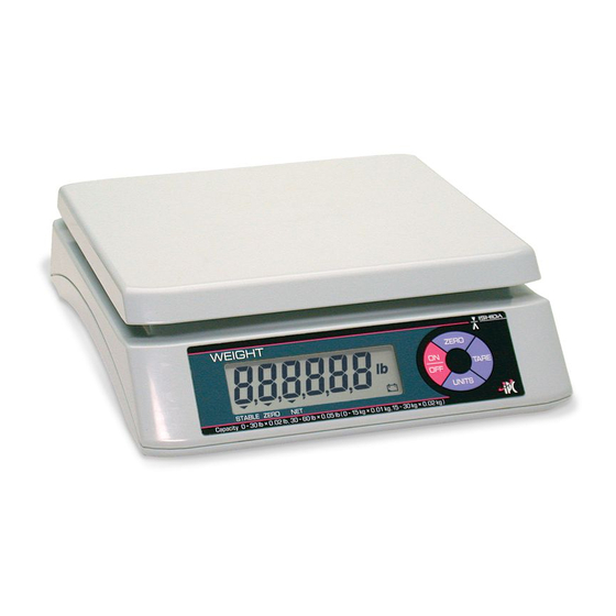
• The IPC Series is a digital scale which can be operated with two batteries. • The large LCD with 25mm height is provided for the display. 1.2 Standard Specifications Item Description Small size Large size Type name IPC 3kg IPC 6kg IPC 15kg IPC 30kg 3kg/ 6kg/ 15kg/ 30kg/ 1g(0~1.5kg) -
Page 5: Appearance
1.3 Appearance F ront view Rear view Bottom view Manual No. 0183B IPC Series Service Manual 4/29... -
Page 6: Operation Panel
1.4 Operation Panel Manual No. 0183B IPC Series Service Manual 5/29... -
Page 7: Outer Dimensions
1.5 Outer Dimensions Small size Large size Manual No. 0183B IPC Series Service Manual 6/29... -
Page 8: Chapter 2 Test Mode
Chapter 2 Test Mode The Test Mode is used for diagnosis and/or setting at maintenance service. 2.1 Operation 2.1.1 Test Mode Flow L003 Program No. display START C1 X Setup of Country No. TARE TARE C2 XX Setup of Scale No. TARE And Decimal point TARE... -
Page 9: Key Functions (When Setting Value)
2.1.2 Key Functions (when setting value) Function - Use at TEST mode startup. (Press this key while the TARE key is depressed.) - Use at TEST mode end - Use when selecting digits. ZERO - Press when fixing values after mode or data selection. TARE - Increments values for each press during data change. -
Page 10: C1 Mode - Country No. Setting
2.1.6 C1 Mode – Country No. Setting 1) Country No. Table Country No. Wei- Item Data Digit ASIA 0: ±10% Start range 1: ±2% 0: Lights on at true zero Zero point mark 1: Lights on at Provisional zero Below true zero 0: "___"... -
Page 11: C2 Mode - Scale No. And Decimal Point Setting
2.1.7 C2 Mode – Scale No. and Decimal point Setting 1) Scale No.[ X1 ] Table Specifications A/D Counts 3kg (2g/1g) Multi interval 30000 (20/10) 6kg (5g/2g) Multi interval 30000 (25/10) 15kg (10g/5g) Multi interval 30000 (20/10) 30kg (20g/10g) Multi interval 30000 (20/10) 3kg (1g) Single range... -
Page 12: C3 Mode - Span Adjustment
3) Operation Operation Display Stating Test Scale No. and Decimal point indication mode - Press the [ TARE ] key ON → (1 digit flashes) - Example: ASIA 3kg (1g) Single range X1=5, X2=4 X2 X1 2.1 Scale No. Setting - Press the [ * ] key ON four times ( X1=5) X2 X1 2.2 Decimal point indication Setting... -
Page 13: F Mode - Setting Measuring Conditions And E2Rom Clear
2.4 Press the ZERO key if the count diverges from 5000 counts. 2.5 Put the weight same as weighing capacity on the weigh platter, then press the [ * ] key → "CAL" is displayed, then the A/D count becomes "35000" on the display. -
Page 14: Error No. List
3. E2ROM clear ・ Any scene of F mode is possible. 3.1 Press the ZERO key and [ * ] key. → "EP-C" then "C1-1" is displayed. At this point, writing in E2ROM of change data in ↓ F mode and the default value to E2ROM clear has not been cpmlpeted. -
Page 15: Chapter 3 Hardware Configuration
Chapter 3 Hardware Configuration 3.1 Mechanisms 3.1.1 Small Size (3kg, 6kg) Manual No. 0183B IPC Series Service Manual 14/29... - Page 16 IPC 3kg、6kg Single Display Asia Service Parts List Parts Name Weighing Capacity Q'ty PLATTER PLATE: SUPPORT LOAD CELL (CZL-6D-C3-5kg-1000) LOAD CELL (CZL-6D-C3-10kg-1000) CASE BASE FOOT: LEVEL BATTERY: COVER LUCENT: PLATE SHEET: DISPLAY: FRONT SHEET: DISPLAY: FRONT SHEET: DISPLAY: REAR SLEEVE...
-
Page 17: Large Size (15Kg、30Kg)
3.1.2 Large Size (15kg、30kg) Manual No. 0183B IPC Series Service Manual 16/29... - Page 18 IPC 15kg,30kg Single Display Asia Service Parts List Parts Name Weighing Capacity Q'ty PLATTER CASE LUCENT: PLATE SHEET: DISPLAY: FRONT 15kg SHEET: DISPLAY: FRONT 30kg SCREW ST 3 x 8 PWB PS-005A PRINTER GND CORD SCREW ST 4 x 14 LOAD CELL (CZL-6D-C3-25kg-1000) 15kg LOAD CELL (CZL-6D-C3-50kg-1000)
-
Page 19: Electric Concerns
3.2 Electric Concerns 3.2.1 Block Diagram Load cell (4 types depending on weighing capacity GND connection Main board PS-005 AC adaptor (Option) Batteries 3.2.2 Board PS-005 (B) (G) Manual No. 0183B IPC Series Service Manual 18/29... - Page 20 Connector CN1: AC adaptor input Pin No. Function Remarks AC adaptor power source DC 2.4 to 6.0V GND (Circuit) GND (Battery) CN2: Battery input Pin No. Function Remarks GND (Battery) Battery power source DC 2.2 to 3.2V CN3: Not used CN4: LCD display data output CN5: Not used CN6: Load cell input...
-
Page 21: Chapter 4 Maintenance
Chapter 4 Maintenance 4.1 Disassembly Procedure (Small Size: 3kg • 6kg) The seal restricts the peel according to the country by a no report and doing as wanting put it. Follow the relevant procedure for the respective countries. 4.1.1 Base Replacement Disassembly procedure 1. -
Page 22: Board Replacement
4.1.2 Board Replacement 1. Remove the load cell cable and grand cable using the soldering iron. 2. Remove the three ST3×8 screws where the board is fixed. 3. The board is fixed with four hooks and one lib as shown in the photo. Press down the place shown by the arrow while pulling towards yourself, then remove the hook 1 by sliding the entire board to the left and out. -
Page 23: Load Cell Replacement
4.1.3 Load Cell Replacement 1. Remove the load cell cable and ground cable by using the soldering iron. 2. Remove the ST4×10 screw which fixes the cable clamp. 3. Remove the four M5×16 screws which fixe the plate support at four case locations. 4. - Page 24 6. Remove the M6×25 hexagonal bolts, spring washers and flat washers, which fix the plate support and load cell in two locations both above and under. 7. Fix a new load cell and fix in four locations on the upper and lower plate support with flat washers, spring washers, and M6×25 hexagonal bolts order.
-
Page 25: Assembly Procedure (Large Size: 15Kg • 30Kg)
4.2 Assembly Procedure (Large Size: 15kg • 30kg) 4.2.1 Base Replacement The seal restricts the peel according to the country by a no report and doing as wanting put it. Do the procedure in a pertinent country. Disassembly procedure 1. Remove two dry batteries when using the batteries. Remove the AC adaptor when using the AC adaptor. -
Page 26: Board Replacement
4.2.2 Board Replacement 1. Remove the load cell cable and ground cable by using the soldering iron. 2. Remove the three ST3×8 screws where the board is fixed. 3. The board is fixed with the four hooks and one lib as shown in the photo. Press down the place shown by the arrow, while pulling towards yourself, then remove the hook 1 by sliding the entire board to the left and out. -
Page 27: Load Cell Replacement
4.2.3 Load Cell Replacement 1. Remove the load cell cable using the soldering iron. 2. Remove the M4×10 screw which fixes the cable clamp, then remove the ground cable and load cell cable. 3. Remove the four ST4×16 screws where the platter and plate support are fixed. 4. - Page 28 7. Start the test mode, and perform the C3 mode span adjustment. Manual No. 0183B IPC Series Service Manual 27/29...
-
Page 29: Troubleshooting
4.3 Troubleshooting Symptom Cause Measure • Check and replace dry batteries 1. The display check does not 1. Trouble of dry battery power start when the power switch is supply system • Confirmation and exchange of pushed. battery harness • Check output voltage (DC2.4-6.0V) 2.
Need help?
Do you have a question about the IPC 3kg and is the answer not in the manual?
Questions and answers