Table of Contents
Advertisement
Quick Links
IMPORTANT
• Read this manual thoroughly, and do not perform
installation, operation, maintenance, or inspection
unless you fully understand all of the contents.
• Keep this manual in a safe place where you can refer
to it easily while installing, operating, and carrying out
maintenance or inspections.
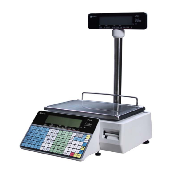
UNI-3
Service Manual
1st Edition
Issued on 30-Nov-2013
Advertisement
Table of Contents

Related Manuals for ISHIDA UNI-3


Summary of Contents for ISHIDA UNI-3
- Page 1 UNI-3 Service Manual 1st Edition IMPORTANT • Read this manual thoroughly, and do not perform installation, operation, maintenance, or inspection unless you fully understand all of the contents. Issued on 30-Nov-2013 • Keep this manual in a safe place where you can refer to it easily while installing, operating, and carrying out maintenance or inspections.
- Page 2 © ISHIDA Co., Ltd. 2012 All rights are reserved. No part of this publication may be reproduced, stored in a retrieval system, or transmitted in any form or by any means mechanical, electronic, photocopying, recording, or otherwise without prior written permission of ISHIDA.
- Page 3 ISHIDA is not liable for any damage, loss or injury that results from incorrect operation, insufficient caution, unauthorized modifications to the machine, or failure to follow the instructions contained in this manual.
- Page 4 Additionally, there may be significant property damage. Indicates a potentially hazardous situation where, if not avoided, may result in minor or moderate injury or in property damage. Indicates reference information for operation. Indicates the referred page for operation. UNI-3 Service Manual...
- Page 5 Dropping the machine may result in injury or cause the machine to break down. • Do not drop the cassette. Dropping the cassette may result in injury or cause the cassette to break down. UNI-3 Service Manual...
- Page 6 • Handle with care when removing or inserting the cassette. Careless cassette handling may result in injury or cause the cassette to break down. • Do not dispose of batteries with normal household waste. Please obey your local regulations when disposing of used batteries. UNI-3 Service Manual...
- Page 7 Do not give the victim anything to drink, and do not rinse the mouth. If vomiting occurs naturally, have the victim lean forward to reduce risk of aspiration. Keep the victim warm and seek medical attention. UNI-3 Service Manual...
-
Page 8: Table Of Contents
WIRELESS LAN BOARD (PK-265) .............. 4-7 Chapter 5 MACHINE DISASSEMBLY DISASSEMBLY PROCEDURE FOR EACH TYPE ........5-1 5.1.1 CASE COVER ....................5-1 5.1.2 SUPPORT AND LOAD CELL ................ 5-3 5.1.3 MAIN BOARD....................5-5 5.1.4 CASE COVER BOARD .................. 5-6 UNI-3 Service Manual... - Page 9 ELEVATED TYPE ..................5-8 5.2.1 POLE UNIT ....................5-8 5.2.2 NOTE FOR SETUP OF ELEVATED TYPE (L2) ......... 5-10 DIFFERENTIAL POINTS FOR EACH COUNTRY ........5-11 Chapter 6 SETUP MODE ................6-1 Chapter 7 ADJUSTMENT MODE..............7-1 UNI-3 Service Manual...
- Page 10 TABLE OF CONTENTS MEMO viii UNI-3 Service Manual...
-
Page 11: Chapter 1 Basic Information
Chapter 1 BASIC INFORMATION BASIC INFORMATION OUTER DIMENSIONS FOR EACH TYPE 1.1.1 OUTER DIMENSIONS FOR BENCH TYPE (unit : mm) UNI-3 Service Manual... -
Page 12: Outer Dimensions For Elevated Type
Chapter 1 BASIC INFORMATION 1.1.2 OUTER DIMENSIONS FOR ELEVATED TYPE (unit : mm) UNI-3 Service Manual... -
Page 13: Outer Dimensions For Pole Type
Chapter 1 BASIC INFORMATION 1.1.3 OUTER DIMENSIONS FOR POLE TYPE (unit : mm) UNI-3 Service Manual... -
Page 14: Outer Dimensions For Hanging Type
Chapter 1 BASIC INFORMATION 1.1.4 OUTER DIMENSIONS FOR HANGING TYPE (unit : mm) UNI-3 Service Manual... -
Page 15: Specifications
Printing effective size 56mm Label size Label width: 38mm to 64mm Label length: 30mm to 175mm Number of label cassettes non cassette Input/Output LAN 1 channel USB 1 channel Drawer 1 channel Program store medium Flash ROM (32M bytes) UNI-3 Service Manual... -
Page 16: Installation
To avoid personal injury and shock, do not open or remove any covers or enclosures of the machine unless specified in the manual. • Do not perform unspecified maintenance. For your personal safety, do not perform any maintenance procedures which are not specified in the manual. UNI-3 Service Manual... -
Page 17: Precautions For Installation
• Places exposed to direct cold sunlight fluctuations • Places where water or other air from air conditioners or liquids are easily spilled on the refrigerators • Places where the floor or machine foundation is unstable UNI-3 Service Manual... - Page 18 Chapter 1 BASIC INFORMATION MEMO UNI-3 Service Manual...
-
Page 19: Chapter 2 Assembly Drawings
Chapter 2 ASSEMBLY DRAWINGS ASSEMBLY DRAWINGS BENCH TYPE (L2) UNI-3 Service Manual... - Page 20 BASE(Loadcell BC-8000) BRACKET'LOCK' HARNESS 'C3' POWER BRACKET'PUSH' POWER CORD HY-01/HY-02 Axis-Hold(BC-6000 Printer) (3×0.75mm²×2m)USA SWITCH(BR-22C-11L-S) TEAR BAR Nameplate(UNI-3 L2BENCH 30lb USA) Bracket(Sensor BC-6000-NL) Connector(UNI-3 UL) Spring Coil 1 PWB'PS-990G-2'MAIN 2M(UNI-3) Spring Coil 2 PWB, PS-067, A/D LABEL SENSOR Assy Cover(Base Port BC-8000)
-
Page 21: Bench Type (L1)
Chapter 2 ASSEMBLY DRAWINGS BENCH TYPE (L1) UNI-3 Service Manual... - Page 22 HARNESS 'C3' POWER POWER SUPPLY LSF10024 BREAKET(FOR PRINTER) Cover-Printerside(UNI-3 UL) Bracket(Magnet) Printer Nameplate(NL)(English) LABEL GND CORD HINGE(Plastic) BUSH(CSB-EPBF-0608-04) Displaysheet Bracket(Cutter) (UNI-3 L1B CUST-M30lb USA) Displaysheet Screw(UNI-3 Cutter) (UNI-3 L1 OP-M30lb USA) MOTOR'STEPPING',49P048L0-00702 ZCAT1518-0730 Bracket Motor(BC-8000) Bracket(Peel Sensor AC-4000B) Bracket01 Peel Sensor...
-
Page 23: Pole Type (L2)
Chapter 2 ASSEMBLY DRAWINGS POLE TYPE (L2) UNI-3 Service Manual... - Page 24 Pole(BC-8000) Bracket(Magnet) Cover(Pole Base BC-8000) LABEL GND CORD Lock-nut(BC-8000) BUSH(CSB-EPBF-0608-04) DisplayCase-B(UNI-3 UL) Bracket(Cutter) DisplayCase-F(UNI-3 UL) Screw(UNI-3 Cutter) Displaysheet(UNI-3 L2 CUST-M30Lb USA) ZCAR1518-0730 DisplayPanel(UNI-3 Cust) Bracket(Peel Sensor AC-4000B) Displaysheet(UNI-3 L2 OP-M30lb USA) Peel Sensor MOTOR'STEPPING',49P048L0-00702 HARNESS PEEL SENSOR L-150mm Bracket Motor(BC-8000)
-
Page 25: Pole Type (L1)
Chapter 2 ASSEMBLY DRAWINGS POLE TYPE (L1) UNI-3 Service Manual... - Page 26 BASE(Loadcell BC-8000) FRAME'HEAD' HARNESS 'C3' POWER BRACKET'HEAD' POWER CORD HY-01/HY-02 Thermal head CHX56-9719A (3×0.75mm²×2m)USA BRACKET'LOCK' SWITCH(BR-22C-11L-S) Nameplate(UNI-3 L1 30lb USA) BRACKET'PUSH' Connector(UNI-3 UL) Axis-Hold(BC-6000 Printer) PWB'PS-990G-2'MAIN 2M(UNI-3) TEAR BAR PWB, PS-067, A/D Bracket(Sensor BC-6000-NL) Cover(Base Port BC-8000) Spring Coil 1...
-
Page 27: Chapter 3 Block Diagrams
CN2 11JQ-BT (PS-067*) XJ18 HIF3FC-26 XJ21 XH-11 (PS-990*) ⑭ ⑫ CUSTOMER L1 DISPLAY ⑬ OPERATOR L1 DISPLAY L1 TYPE DISPLAY CN1 HIF3FC26 MEMBRANE KEY SHEET CN2 1-520315-6 PS-068* (UNI-3 type) TACTILE KEY BOARD CN3 520315-8 (UNI-3 type) KEY UNIT UNI-3 Service Manual... -
Page 28: Block Diagram (Hanging Type)
XJ25 ⑯ USB-A XJ19 PH-6 USB-A ⑪ CN2 11JQ-BT (PS-067*) PEEL SENSOR XJ18 HIF3FC-26 XJ21 XH-11 (PS-990*) ⑭ MEMBRANE KEY SHEET CN1 HIF3FC26 CN2 1-520315-6 PS-037* (BC-4000H type) TACTILE KEY BOARD CN3 520315-8 (BC-4000H type) KEY UNIT UNI-3 Service Manual... -
Page 29: Harness List
L1 Pole type customer side display (display side) ⑬ L1 type operator side display ⑭Bench/Pole Bench/Pole type key ⑭Elevated -1 Elevated type key (main board side) ⑭Elevated -2 Elevated type key (key side) ⑭Hanging Hanging type key ⑮ TCP/IP unit ⑯ USB extension cable UNI-3 Service Manual... - Page 30 Chapter 3 BLOCK DIAGRAMS MEMO UNI-3 Service Manual...
-
Page 31: Chapter 4 Electrical Signals
Opposite Side <--> <--> <--> Not connected Not connected <--> Not connected Not connected Signal Name Direction Opposite Side Unused DC+24V for drawer Cash drawer GND for drawer Unused Signal Name Direction Opposite Side DC+5V Wireless LAN UNI-3 Service Manual... - Page 32 DC+24V main power supply Switching power supply 4,5,6 XJ11 Signal Name Direction Opposite Side DC+5V 3,4,6,10,27 Thermal head control signal -> 5,7,8,9,28 Not connected Thermal head 11,12 Thermistor input signal <- 13,14,15,16,17, 18,19 20,21,22,23,24, DC+24V for thermal head 25,26 UNI-3 Service Manual...
- Page 33 Key data PS-068 (B/P/EV) 14,15,16,17,18, <- KD0 - KD14 PS-037 (H) 19,20,21,22,23 24,25,26 Not connected XJ19,20 Signal Name Direction Opposite Side DC+5V XJ19 : Customer side display (L1) XJ20 : Operator side display (L1) LCD control signal <--> UNI-3 Service Manual...
- Page 34 DC+12V for A/D board XJ22 Signal Name Direction Opposite Side Battery+ Back up power Jumper Not connected XJ25 Signal Name Direction Opposite Side Vbus <--> USB memory <--> XJ101 Signal Name Direction Opposite Side DC+5V -> Scanner -> <- <- UNI-3 Service Manual...
-
Page 35: A/D Board
Not connected Signal Name Direction Opposite Side 1,2,3,4,5, Key data 6,7,8,9,10, <- KD0 - KD13 Membrane key sheet 11,12,13,14 15,16 Not connected Signal Name Direction Opposite Side 1,2,3,4,5, Key scanning -> Membrane key sheet 6,7,8 KS0 - KS7 UNI-3 Service Manual... -
Page 36: L1 Type Lcd Display Board
Signal Name Direction Opposite Side Not connected LED CATHODE (Y/G) LED ANODE (Y/G) 5,6,7,8,9, LCD data signal <- 10,11,12 D0 - D7 <- Main board PS-990* XJ7, 8 <- 15,16,17 E1, E2, E3 <- RESET# <- DC+5V UNI-3 Service Manual... -
Page 37: Wireless Lan Board (Pk-265)
Chapter 4 ELECTRICAL SIGNALS WIRELESS LAN BOARD (PK-265) Signal Name Direction Opposite Side DC+5V Main board PS-990* XJ5 Signal Name Direction Opposite Side -> -> <- <- Main board PS-990* XJ1 LEDR LEDL 4,7,13,14 9,12 DC+3.3V UNI-3 Service Manual... - Page 38 Chapter 4 ELECTRICAL SIGNALS MEMO UNI-3 Service Manual...
-
Page 39: Chapter 5 Machine Disassembly
OPERATION DISPLAY of ELEVATED TYPE, refer to the section 5.2 ELEVATED TYPE. 5.1.1 CASE COVER Detach the platter. Remove the six screws (orange) and one hex screw (8 mm, green). Open the side cover. Detach the cover. UNI-3 Service Manual... - Page 40 Chapter 5 MACHINE DISASSEMBLY Displace the cover upward to disengage Unplug the connector. the hook from the cover. Unplug the connector. Remove the case cover. * Reverse this procedure for assembly. UNI-3 Service Manual...
-
Page 41: Support And Load Cell
Chapter 5 MACHINE DISASSEMBLY 5.1.2 SUPPORT AND LOAD CELL Remove the two hex screws (5 mm). Remove the support. Remove the five screws. Slide the cassette unit. Remove the five hex screws (4 mm). UNI-3 Service Manual... - Page 42 Chapter 5 MACHINE DISASSEMBLY Unplug the connector. Remove the two hex screws . Detach the lord cell unit. When replacing the load cell, remove the solder. * Reverse this procedure for assembly. UNI-3 Service Manual...
-
Page 43: Main Board
Remove the six screws. Unplug the eight connectors. Remove the four screws. Remove the main board. Unplug the connector. Mounting position of the L1 display (orange) Mounting position of the L2 display (white) Reverse this procedure for assembly. UNI-3 Service Manual... -
Page 44: Case Cover Board
Remove the four screws (L2, white). Remove the four screws and unplug the two Remove the keypad board. flexible cables When replacing the customer side panel, remove the five tabs. * Reverse this procedure for assembly. UNI-3 Service Manual... -
Page 45: Power Board
Open the side cover and remove the While holding the plate, remove the two cassette cover. screws. Push up the plate. Pull out the thermal head and unplug the connector. Set the original position for assembly. * Reverse this procedure for assembly. UNI-3 Service Manual... -
Page 46: Elevated Type
CAUTION: Make sure to unplug the power cord from the wall outlet before starting the disassembly work. 5.2.1 POLE UNIT Remove the platter. Remove the three screws. Platter Detach the cover. Unplug the two connectors. The Operators side UNI-3 Service Manual... - Page 47 Remove the two screws and detach the cover. Remove the four screws and unplug the Remove the five screws and detach the connector to detach the display board. pole unit. Remove the seven screws and remove the Remove the plate. plate. UNI-3 Service Manual...
-
Page 48: Note For Setup Of Elevated Type (L2)
Turn on the power and check the display after completing the connection. Operator side display Customer side display When completing the start-up, the date and time is displayed on the operator side display, and the message “WE WILL SERVE YOU SOON” on the customer side display. 5-10 UNI-3 Service Manual... -
Page 49: Differential Points For Each Country
Chapter 5 MACHINE DISASSEMBLY DIFFERENTIAL POINTS FOR EACH COUNTRY UNI-3 Service Manual 5-11... - Page 50 Chapter 5 MACHINE DISASSEMBLY 5-12 UNI-3 Service Manual...
-
Page 51: Chapter 6 Setup Mode
Chapter 6 SETUP MODE SETUP MODE The UNI-3 standard specification The SETUP MODE for this device includes the following items: 1.MACHINE No. 11.CASSETTE 22.PRICE ROUNDING 2.SALES MODE 12.LABEL SPEC. 23.FREQUENT SHOPPER 3.PASSWORD 13.LABEL FORMAT 26.COUNTRY 5.DATA STORAGE 14.BARCODE 27.FILE SAVE/LOAD 6.PRESET REPORT... - Page 52 SLP live or dead check: Time out time *FTP USER User name for FTP transmission *FTP PASS Password for FTP transmission *PRESET FUNC 4.WiFi *SECURITY *KEY TYPE Encryption setup ASCII/HEX (hexadecimal) *SSID(WIRELESS NETWORK) Enter from SSID editor. *WEP KEY INDEX Select 1~4. UNI-3 Service Manual...
- Page 53 Setup Satellite machine to "3 SAT" and operate as Satellite scale. When operating CSIS, set up an individual IP ADDRESS for each meter using "B01-02-01." Also, set up Satellite scale to Master machine IP ADDRESS to allow communication. UNI-3 Service Manual...
- Page 54 Specify the product Master referent. Select whether to use the Satellite machine's internal Master or call the Master machine each time. When using the internal Master in response priority mode, in order to update the Master in real time, specify the Master machine and call in real time. UNI-3 Service Manual...
- Page 55 B 0 1 - 0 1 - 0 6 P O R T * * * * * The port number of master scale. Master Scale Port No. Specify the Port No. for socket transmission. Default No. 55101 UNI-3 Service Manual...
- Page 56 Enter IP address of Master Scale. &&&.$$$.###.*** Specify Master Machine when connecting to CSIS Satellite. The IP address you specify here is recognized as the Master Machine and transmits as the Master Machine when connecting to Satellite. UNI-3 Service Manual...
- Page 57 10 11 12 13 14 15 16 17 18 19 20 21 22 23 24 < A D D R > [ E N T ] The segment display B 0 1 - 0 2 < A D D E > UNI-3 Service Manual...
- Page 58 0 . 0 . 0 . 0 Enter GATEWAY address of scale. ***.***.***.***(3 digits + 3 digits + 3 digits + 3 digits) Enter without 0 suppression. When checking with [ENTER] key, the displayed data will suppress 0. UNI-3 Service Manual...
- Page 59 * P O R T The segment display B 0 1 - 0 3 - 0 2 P O R T 8 0 7 1 The port number of Satellite scale. PC Port Number When connecting to SLP-V, specify 8071. UNI-3 Service Manual...
- Page 60 B01-03-06 FTP PASS(MORE THAN 8 CHARS) The dot display 10 11 12 13 14 15 16 17 18 19 20 21 22 23 24 * F T P P A S S [ E D I T ] 6-10 UNI-3 Service Manual...
- Page 61 * S E C U R I T Y - 1 : N O N E The segment display B 0 1 - 0 4 - 0 1 S E C U R I T Y 1:NONE 2:WEP64 3:WEP128 4:WEP64 Shared Key 6-11 UNI-3 Service Manual...
- Page 62 Chapter 6 SETUP MODE 5:WEP128 ShKey 6:WPA PSK TKIP 7:WPA PSK CCMP 8:WPA2 PSK TKIP 9:WPA2 PSK CCMP Specify encryption mode for wireless transmission. 6-12 UNI-3 Service Manual...
- Page 63 I N D E X - 1 : 1 The segment display B 0 1 - 0 4 - 0 4 W E P K E Y I N D Specify WEP key index. Select 1~4. 6-13 UNI-3 Service Manual...
- Page 64 [ Z E R O ] The segment display B 0 1 - 0 3 - 0 8 P I N G P C [ Z ] Execute PING in order to test connection to PC. 6-14 UNI-3 Service Manual...
- Page 65 4: CR SUBTOTAL ONLY (issue label only when settling accounts or issue receipt) 6: CR FIXED OPERATOR (sales mode for fixed operator) Select sales mode. Use 1 and 2 with SM. Use 3~6 with CR sales mode. 6-15 UNI-3 Service Manual...
- Page 66 C L R - 2 : N O U S E The segment display B 0 3 - 2 0 1 0 T T L C L R Menu items that can be specified. 1:USE 2:NO USE 6-16 UNI-3 Service Manual...
- Page 67 3021 FREEMSG02 3022 FREEMSG03 3023 FREEMSG04 3024 FREEMSG05 3025 FREEMSG06 3026 FREEMSG07 3027 FREEMSG08 3028 FREEMSG09 3029 FREEMSG10 3030 FREEMSG11 3031 FREEMSG12 3032 FREEMSG13 3033 FREEMSG14 3034 FREEMSG15 3035 F/P SYM 3036 MINCE TRCB 3039 STMPPRICE 6-17 UNI-3 Service Manual...
- Page 68 * W E E K L Y T O T A L - 2 : A D D The segment display W E E K L Y T O T A B 0 5 - 0 1 - 0 2 6-18 UNI-3 Service Manual...
- Page 69 * C R P R O . T O T A L - 2 : A D D The segment display B 0 5 - 0 1 - 0 9 P R O T O T A 6-19 UNI-3 Service Manual...
- Page 70 * F / P A D D W G T - 1 : F I X W G T The segment display F I X P R I C E B 0 5 - 0 2 - 0 1 6-20 UNI-3 Service Manual...
- Page 71 T R A N S - 1 : N O N A D D The segment display B 0 5 - 0 3 - 0 1 P R O D T R A N S 1:NON ADD 2:ADD 6-21 UNI-3 Service Manual...
- Page 72 - 1 : S T O P The segment display M E M F U L L B 0 5 - 0 3 - 0 4 1:STOP 2:OVER WRITE Select the processing when actual addition overload occurs. 6-22 UNI-3 Service Manual...
- Page 73 10 11 12 13 14 15 16 17 18 19 20 21 22 23 24 < S T O R A G E > [ E N T ] The segment display < S T O R A G E > B 0 5 - 0 4 6-23 UNI-3 Service Manual...
- Page 74 10 11 12 13 14 15 16 17 18 19 20 21 22 23 24 < D A I L Y > [ E N T ] The segment display < D A I L Y B 0 6 - 0 1 - > 6-24 UNI-3 Service Manual...
- Page 75 10 11 12 13 14 15 16 17 18 19 20 21 22 23 24 D E P T - 1 : N O P R N The segment display D E P T B 0 6 - 0 1 - 0 3 6-25 UNI-3 Service Manual...
- Page 76 10 11 12 13 14 15 16 17 18 19 20 21 22 23 24 * P L U A B C - 2 - 1 : N O P R N The segment display P L U A B C - 2 B 0 6 - 0 1 - 6-26 UNI-3 Service Manual...
- Page 77 10 11 12 13 14 15 16 17 18 19 20 21 22 23 24 * P L U Z - 3 - 1 : N O P R N The segment display P L U Z - 3 B 0 6 - 0 1 - 6-27 UNI-3 Service Manual...
- Page 78 * D E P T A B C - 3 - 1 : N O P R N The segment display D E P T A B C - 3 B 0 6 - 0 1 - 1 5 6-28 UNI-3 Service Manual...
- Page 79 10 11 12 13 14 15 16 17 18 19 20 21 22 23 24 * D E P T Z - 4 - 1 : N O P R N The segment display D E P T Z - 4 B 0 6 - 0 1 - 1 9 6-29 UNI-3 Service Manual...
- Page 80 * G R O U P A B C - 4 1 : N O P R N The segment display G R O U P A B C - 4 B 0 6 - 0 1 - 2 3 6-30 UNI-3 Service Manual...
- Page 81 10 11 12 13 14 15 16 17 18 19 20 21 22 23 24 A C C 1 - 1 : N O P R N The segment display A C C 1 B 0 6 - 0 1 - 2 7 6-31 UNI-3 Service Manual...
- Page 82 10 11 12 13 14 15 16 17 18 19 20 21 22 23 24 P R O M O - 1 : N O P R N The segment display P R O M O B 0 6 - 0 1 - 6-32 UNI-3 Service Manual...
- Page 83 10 11 12 13 14 15 16 17 18 19 20 21 22 23 24 H O U R - 1 : N O P R N The segment display H O U R B 0 6 - 0 2 - 0 2 6-33 UNI-3 Service Manual...
- Page 84 10 11 12 13 14 15 16 17 18 19 20 21 22 23 24 H O U R - 1 : N O P R N The segment display B 0 6 - 0 3 - 0 2 H O U R 6-34 UNI-3 Service Manual...
- Page 85 10 11 12 13 14 15 16 17 18 19 20 21 22 23 24 * P L U A B C - 1 - 1 : N O P R N The segment display B 0 6 - 0 3 - P L U A B C - 1 6-35 UNI-3 Service Manual...
- Page 86 10 11 12 13 14 15 16 17 18 19 20 21 22 23 24 * P L U Z - 2 - 1 : N O P R N The segment display P L U Z - 2 B 0 6 - 0 3 - 6-36 UNI-3 Service Manual...
- Page 87 * D E P T A B C - 2 - 1 : N O P R N The segment display D E P T A B C - 2 B 0 6 - 0 3 - 6-37 UNI-3 Service Manual...
- Page 88 10 11 12 13 14 15 16 17 18 19 20 21 22 23 24 * D E P T Z - 3 - 1 : N O P R N The segment display D E P T Z - 3 B 0 6 - 0 3 - 6-38 UNI-3 Service Manual...
- Page 89 * G R O U P A B C - 3 - 1 : N O P R N The segment display G R O U P A B C - 3 B 0 6 - 0 3 - 6-39 UNI-3 Service Manual...
- Page 90 10 11 12 13 14 15 16 17 18 19 20 21 22 23 24 * G R O U P Z - 4 - 1 : N O P R N The segment display B 0 6 - 0 3 - G R O U P Z - 4 6-40 UNI-3 Service Manual...
- Page 91 * U N I T T Y P E : Q T Y - 2 : N O The segment display B 0 7 - 0 3 U N I T T Y P E Q T Y 6-41 UNI-3 Service Manual...
- Page 92 10 11 12 13 14 15 16 17 18 19 20 21 22 23 24 * T A R E - 2 : N O The segment display B 0 7 - 0 8 T A R E 6-42 UNI-3 Service Manual...
- Page 93 10 11 12 13 14 15 16 17 18 19 20 21 22 23 24 * C O U P O N M S G . - 2 : N O The segment display C O U P O N M S G B 0 7 - 1 3 6-43 UNI-3 Service Manual...
- Page 94 10 11 12 13 14 15 16 17 18 19 20 21 22 23 24 * F R E E M S G . - 2 : N O The segment display F R E E M S G B 0 7 - 6-44 UNI-3 Service Manual...
- Page 95 10 11 12 13 14 15 16 17 18 19 20 21 22 23 24 * F R E E M S G . - 2 : N O The segment display F R E E M S G B 0 7 - 6-45 UNI-3 Service Manual...
- Page 96 10 11 12 13 14 15 16 17 18 19 20 21 22 23 24 * F R E E M S G . 1 1 - 2 : N O The segment display F R E E M S G 1 1 B 0 7 - 6-46 UNI-3 Service Manual...
- Page 97 10 11 12 13 14 15 16 17 18 19 20 21 22 23 24 * F R E E M S G . 1 5 - 2 : N O The segment display F R E E M S G 1 5 B 0 7 - 6-47 UNI-3 Service Manual...
- Page 98 * S H . I M A G E F L A G - 2 : N O The segment display I M A G E F L A G B 0 7 - 3 4 6-48 UNI-3 Service Manual...
- Page 99 10 11 12 13 14 15 16 17 18 19 20 21 22 23 24 * U S E D A T E - 2 : N O The segment display U S E D A T E B 0 7 - 6-49 UNI-3 Service Manual...
- Page 100 14:LOWER WEIGHT 11:FREE MESSAGE 4 15:UPPER WEIGHT 12:FREE MESSAGE 5 13:FREE MESSAGE 6 14:FREE MESSAGE 7 15:FREE MESSAGE 8 16:FREE MESSAGE 9 17:FREE MESSAGE10 18:FREE MESSAGE11 19:FREE MESSAGE12 20:FREE MESSAGE13 21:FREE MESSAGE14 22:FREE MESSAGE15 23:NUTRITION TEXT 6-50 UNI-3 Service Manual...
- Page 101 10 11 12 13 14 15 16 17 18 19 20 21 22 23 24 * S A L E S - 0 : W E I G H T The segment display B 0 8 - 0 1 - 0 1 S A L E S 6-51 UNI-3 Service Manual...
- Page 102 10 11 12 13 14 15 16 17 18 19 20 21 22 23 24 * U N I T P R I C E The segment display B 0 8 - 0 1 - 0 4 P R I C E X X X X X X 6-52 UNI-3 Service Manual...
- Page 103 The dot display 10 11 12 13 14 15 16 17 18 19 20 21 22 23 24 * T A X The segment display B 0 8 - 0 1 - 0 8 T A X 6-53 UNI-3 Service Manual...
- Page 104 10 11 12 13 14 15 16 17 18 19 20 21 22 23 24 * U P P E R W G T The segment display B 0 8 - 0 1 - 1 5 W G T X X X X 6-54 UNI-3 Service Manual...
- Page 105 10 11 12 13 14 15 16 17 18 19 20 21 22 23 24 * P O I N T S The segment display B 0 8 - 0 2 - 0 8 P O I N T S 6-55 UNI-3 Service Manual...
- Page 106 10 11 12 13 14 15 16 17 18 19 20 21 22 23 24 * X T R A M S G 2 The segment display B 0 8 - 0 3 - 0 3 M E S G 2 X X X X X X 6-56 UNI-3 Service Manual...
- Page 107 10 11 12 13 14 15 16 17 18 19 20 21 22 23 24 * C O O K T I M E The segment display B 0 8 - 0 3 - 0 7 C O O K 6-57 UNI-3 Service Manual...
- Page 108 10 11 12 13 14 15 16 17 18 19 20 21 22 23 24 * F R E E M S G 0 4 The segment display B 0 8 - 0 3 - 1 1 F M G 0 4 X X X X X X 6-58 UNI-3 Service Manual...
- Page 109 10 11 12 13 14 15 16 17 18 19 20 21 22 23 24 * F R E E M S G 0 8 The segment display B 0 8 - 0 3 - 1 5 F M G 0 8 X X X X X X 6-59 UNI-3 Service Manual...
- Page 110 10 11 12 13 14 15 16 17 18 19 20 21 22 23 24 * F R E E M S G 1 2 The segment display B 0 8 - 0 3 - 1 9 F M G 1 2 X X X X X X 6-60 UNI-3 Service Manual...
- Page 111 * N U T . T X T The segment display 10 11 15 16 17 18 B 0 8 - 0 3 - 2 3 N. T X T X X X X X X 6-61 UNI-3 Service Manual...
- Page 112 10 11 12 13 14 15 16 17 18 19 20 21 22 23 24 * I M A G E The segment display B 0 8 - 0 4 - 0 3 I M A G E X X X 6-62 UNI-3 Service Manual...
- Page 113 * F I R S T L A B E L F O R M A T ( M ) The segment display B 0 8 - 0 5 - 0 1 1 S T F M T X X X 6-63 UNI-3 Service Manual...
- Page 114 * 2 n d L B L P R I N T - 2 : N O The segment display B 0 8 - 0 5 - 0 5 2 N D L B L P R N 6-64 UNI-3 Service Manual...
- Page 115 * S B D A T E P R I N T - 1 : Y E S The segment display B 0 8 - 0 6 - 0 4 D A T E P R N 6-65 UNI-3 Service Manual...
- Page 116 10 11 12 13 14 15 16 17 18 19 20 21 22 23 24 * U S E D A T E P R N - 2 : N O The segment display B 0 8 - 0 6 - 0 8 D A T E P R N 6-66 UNI-3 Service Manual...
- Page 117 10 11 12 13 14 15 16 17 18 19 20 21 22 23 24 * P O S F L A G 2 D I G I T S The segment display B 0 8 - 0 7 - 0 3 P O S F L A G 6-67 UNI-3 Service Manual...
- Page 118 10 11 12 13 14 15 16 17 18 19 20 21 22 23 24 * P O S F M T - 0 : R E F E R The segment display B 0 8 - 0 7 - 0 7 P O S F M T 6-68 UNI-3 Service Manual...
- Page 119 10 11 12 13 14 15 16 17 18 19 20 21 22 23 24 < L I N K > [ E N T ] The segment display B 0 8 - 0 8 < L I N K > 6-69 UNI-3 Service Manual...
- Page 120 10 11 12 13 14 15 16 17 18 19 20 21 22 23 24 * L i n k P L U N O . The segment display B 0 8 - 0 8 - 0 1 P L U . N O . 6-70 UNI-3 Service Manual...
- Page 121 R E C E I P T N o . > [ E N T ] The segment display < R E C E I P T N o . > B 1 0 - 0 3 6-71 UNI-3 Service Manual...
- Page 122 1:01 3922 3203 2:01 3922 3203 15 B10-01 Enter footer and header text to print on receipt. Specify logo image for header and footer. B10-02 Specify barcode to print on receipt. POS flag + POS code (receipt code) 6-72 UNI-3 Service Manual...
- Page 123 POS FORMAT: Select barcode format when selecting EAN13 F2C5pP4d F2C6P4d F1C6pP4d F2C5P5d F1C6P5d F2C4pP5d F2C6W4d F1C6W5d F1C5i6d F2C6P4d* F2C6W4d* F2C4wW5d ---- ---- F2C5oP4d F2C5W5d F2C5P5/10d F2C5pP4/10d F2C5wW4d F1C5P6d F2C4P6d F1C3W4P4d F2C4Q2P4d F1i6P5d F2i6P4d F1C4P7d F1i6P5/10d F2i6P4/10d F1C6P5/10d F2C6P4/10d 6-73 UNI-3 Service Manual...
- Page 124 *: Due to Sweden EAN flag code varies to correspond to the number of digits in the weight and amount values and therefore 4-digit data is reduced in correspondence with the flag code. 1/10,1/100 For details, see European barcode regulations. 6-74 UNI-3 Service Manual...
- Page 125 0000 Image height *HT IMG1 0000 B11-25 HT IMG1 0000 Image height *HT IMG2 0000 B11-26 HT IMG2 0000 Image height *HT IMG3 0000 B11-27 HT IMG3 0000 Image height *RESERVE B11-28 RESERVE Not in use 6-75 UNI-3 Service Manual...
- Page 126 Continuously fed paper can accept different printing areas on the label according to different registration details and can be customized to have a fixed length or variable length according to the above setting values by specifying each. 6-76 UNI-3 Service Manual...
- Page 127 Execute all types of settings in accordance with the size of the label in use. When using a receipt, set the heat-sensitive paper type for the receipt. Details on CR (When printing receipt, use this setting. ) 6-77 UNI-3 Service Manual...
- Page 128 * F O R M A T N O . + [ P L U ] The segment display B 1 3 - 0 1 - 0 1 F O R M A T Select format no. for editing. 6-78 UNI-3 Service Manual...
- Page 129 10 11 12 13 14 15 16 17 18 19 20 21 22 23 24 < U N I T > [ E N T ] The segment display B 1 3 - 0 2 < U N I T > 6-79 UNI-3 Service Manual...
- Page 130 10 11 12 13 14 15 16 17 18 19 20 21 22 23 24 * Y - A X I S 4 4 0 The segment display B 1 3 - 0 2 - 0 3 Y - A X I S 4 4 0 Specification of Y coordinate 6-80 UNI-3 Service Manual...
- Page 131 10 11 12 13 14 15 16 17 18 19 20 21 22 23 24 < I T E M C O D E > [ E N T ] The segment display < I T E M C O D E > B 1 4 - 6-81 UNI-3 Service Manual...
- Page 132 2:01 3922 3203 15 3:01 3903 3922 4:01 3203 15 3922 *POS WGT -1:F2C5pP4d B14-02-04 POS WGT Select barcode format for EAN13 Barcode for indefinite quantity 01,F2C5pP4d 02,F2C6P4d 03,F1C6pP4d 04,F2C5P5d 05,F1C6P5d 06,F2C4pP5d 07,F2C6W4d 08,F1C6W5d 09,F1C5i6d 10,F2C6P4d* 11,F2C6W4d* 12,F2C4wW5d 15,F2C5oP4d 6-82 UNI-3 Service Manual...
- Page 133 33,---- 34,F2S1R3pP5d 35,F2S1C3pP5d *POS F/P -1:F2C5pP4d B14-02-05 POS F/P Select barcode format for EAN13 Barcode for fixed amount 01,F2C5pP4d 02,F2C6P4d 03,F1C6pP4d 04,F2C5P5d 05,F1C6P5d 06,F2C4pP5d 07,F2C6W4d 08,F1C6W5d 09,F1C5I6d 10,F2C6P4d* 11,F2C6W4d* 12,F2C4wW5d 15,F2C5oP4d 16,F2C5W5d 17,F2C5P5/10d 18,F2C5pP4/10d 19,F2C5wW4d 20,F1C5P6d 6-83 UNI-3 Service Manual...
- Page 134 *GROUP No.DIGIT SET B14-03-02 GROUP No. Middle category code Position and no. of digits *EAN/UPC-13 DIG.SET B14-03-03 EAN/UPC-13 Product code Obtained position and digits *EAN/UPC-8 DIG. SET B14-03-04 EAN/UPC-8 Product code Obtained position 6-84 UNI-3 Service Manual...
- Page 135 Specify the position and no. of digits in order to obtain product code from 8 digits of ITEMCODE.. Pos code inserted into barcode obtains GTIN as priority if GTIN is registered. If GTIN is not registered, position data specified from 8-digit ITEMCODE is obtained. 6-85 UNI-3 Service Manual...
- Page 136 10 11 12 13 14 15 16 17 18 19 20 21 22 23 24 < T I M E R > [ E N T ] The segment display < T I M E R > B 1 7 - 6-86 UNI-3 Service Manual...
- Page 137 10 11 12 13 14 15 16 17 18 19 20 21 22 23 24 < L O G > [ E N T ] The segment display B 1 7 - < L O G > 6-87 UNI-3 Service Manual...
- Page 138 12 13 14 15 16 17 18 19 20 21 22 23 24 < S U B - T O T A L > [ E N T ] The segment display < S U B - T O T A L > B 1 7 - 6-88 UNI-3 Service Manual...
- Page 139 B17-03-07 SEG.PLU TMR Timer setting to display product name for a determined time on segment display *ITEM DISP -1:NO B17-04-01 ITEMS DISP Display details when CR FIX 1:NO 2:YES *VAT PRINT -1:NO B17-04-02 VAT PRINT Print VAT 6-89 UNI-3 Service Manual...
- Page 140 4:5 DIGIT 5:6 DIGIT 6:7DIGIT 7:8 DIGIT 8:TIMER *AUTO TMR(msec) B17-10-02 AUTO TMR *ITEM CODE DIGITS B17-11-01 ITEM CODE *PACK RUN TOT -1:BUZZER B17-12-01 PACK RUN TO 1:BUZZER 2:BUZ+CLR *SUBTOTAL COUNT -1:1 B17-12-02 SUBTOTAL CO 1 1:1 2:2 6-90 UNI-3 Service Manual...
- Page 141 10 11 12 13 14 15 16 17 18 19 20 21 22 23 24 < C O M M O N > [ E N T ] The segment display < C O M M O N > B 1 8 - 6-91 UNI-3 Service Manual...
- Page 142 1: Detect first time 2: Detect each time 3: No error message Setting for customization of UNI-3 error detection method Items for which error detection is not required can be made to continuously operate by selecting No Error Detection. 6-92...
- Page 143 T O T A L - 1 : N O N A D D The segment display B 2 0 - 0 2 T R C B T O T A L Add switch for traceability total 1:NON ADD 2:ADD 6-93 UNI-3 Service Manual...
- Page 144 B 2 0 - 0 5 L O O K U P T B L E D T Selection switch to Display/Do not display LOOKUP TABLE edit button on traceability screen in weigh mode 1: NO 2:YES 6-94 UNI-3 Service Manual...
- Page 145 Since currency symbol is a character string, edit after starting up editor. Set if the currency is used in 2 countries. Also, set when intending to use 2 currencies during the transition period when transferring from local currency into Euros. 6-95 UNI-3 Service Manual...
- Page 146 B22-04 SUB-T PRICE ROUND 1 Subtotal amount rounding 1:NONE 2:05 Specify rounding processing for fractions in the results of price amount calculations. When using 05 Round, determine whether to round for each product or only the subtotal amount. 6-96 UNI-3 Service Manual...
- Page 147 Specification in order to use amount for general customers and member prices. Select whether to print member price or normal price as barcode amount. Specify the LOGO image for discounts that are automatically printed when calling discount products. Other images may be printed for normal products. 6-97 UNI-3 Service Manual...
- Page 148 C O U N T R Y When this sub menu is displayed, setting languages is only one possible operation. Dot display Segment display Setting value *LANGUAGE 1:ENGLISH B26-01-02 LANG Select language file 1:ENGLISH 2:FRENCH 3:GERMAN 4:ITALIAN 5:DUTCH 6:SPANISH 8:ENG-S.AFR 9:SWEDISH 6-98 UNI-3 Service Manual...
- Page 149 U S B D A T A D E L > [ E N T ] The segment display B 2 7 - 0 3 < U S B D A T A D E L > 6-99 UNI-3 Service Manual...
- Page 150 Maximum of 7 folders from USB01 to USB07 *USB DATA 01 [PLU] B27-201 USB DATA 01 >P< Selection status of USB01 If the folder name is registered, the folder name will be displayed. Press the [PLU] button to make 6-100 UNI-3 Service Manual...
- Page 151 14027-0000 EXEC OR STOP Press [PLU] button again on Execute Confirmation Screen to execute. Record scale backup master data in USB memory. Since you can create 1~7 folders within the USB memory, restore data backup and restore stored data. 6-101 UNI-3 Service Manual...
- Page 152 A D D R E S S The segment display B 2 8 - 0 1 - 0 2 0 . 0 . 0 . ***.***.***.***(3 digits + 3 digits + 3 digits + 3 digits).Enter without 0 suppression. 6-102 UNI-3 Service Manual...
- Page 153 → 1 : Y E S The segment display B 2 8 - 0 2 - 0 2 C A M P A I G N Campaign master (uni-3 simple registration not supported) 1:YES (perform master maintenance) 2:NO (do not perform master maintenance) 6-103...
- Page 154 B 2 8 - 0 2 - 0 4 P R S T K E Y L C D Preset Key Master (LCD) not supported on UNI-3 standard 1:YES (perform master maintenance) 2:NO (do not perform master maintenance) The dot display...
- Page 155 The segment display B 2 8 - 0 2 - 0 8 D E P A R T M E N T Department name (main category) 1:YES (perform master maintenance) 2:NO (do not perform master maintenance) 6-105 UNI-3 Service Manual...
- Page 156 The segment display B 2 8 - 0 2 - 1 1 N U T R I T I O N Nutrition master (exclusive to USA/Canada) 1:YES (perform master maintenance) 2:NO (do not perform master maintenance) 6-106 UNI-3 Service Manual...
- Page 157 → 1 : Y E S The segment display B 2 8 - 0 2 - 1 4 X T R A M S G 3 Extra message 3 1:YES (perform master maintenance) 2:NO (do not perform master maintenance) 6-107 UNI-3 Service Manual...
- Page 158 The segment display B 2 8 - 0 2 - 1 7 S C H T B L B A S Schema Table (Europe data for traceability) 1:YES (perform master maintenance) 2:NO (do not perform master maintenance) 6-108 UNI-3 Service Manual...
- Page 159 The segment display B 2 8 - 0 2 - 2 0 L O O K U P D A T A Lookup Data (Europe data for traceability) 1:YES (perform master maintenance) 2:NO (do not perform master maintenance) 6-109 UNI-3 Service Manual...
- Page 160 → 1 : Y E S The segment display B 2 8 - 0 2 - 2 3 F R E E M S G 0 2 Free message 02 1:YES (perform master maintenance) 2:NO (do not perform master maintenance) 6-110 UNI-3 Service Manual...
- Page 161 → 1 : Y E S The segment display B 2 8 - 0 2 - 2 6 F R E E M S G 0 5 Free message 05 1:YES (perform master maintenance) 2:NO (do not perform master maintenance) 6-111 UNI-3 Service Manual...
- Page 162 → 1 : Y E S The segment display B 2 8 - 0 2 - 2 9 F R E E M S G 0 8 Free message 08 1:YES (perform master maintenance) 2:NO (do not perform master maintenance) 6-112 UNI-3 Service Manual...
- Page 163 → 1 : Y E S The segment display B 2 8 - 0 2 - 3 2 F R E E M S G 1 1 Free message 11 1:YES (perform master maintenance) 2:NO (do not perform master maintenance) 6-113 UNI-3 Service Manual...
- Page 164 → 1 : Y E S The segment display B 2 8 - 0 2 - 3 5 F R E E M S G 1 4 Free message 14 1:YES (perform master maintenance) 2:NO (do not perform master maintenance) 6-114 UNI-3 Service Manual...
- Page 165 The segment display B 2 8 - 0 2 - 3 8 D I S P I M A G E Display image (not supported in UNI-3 standard) 1:YES (perform master maintenance) 2:NO (do not perform master maintenance) 6-115 UNI-3 Service Manual...
- Page 166 * L A B E L → 1 : Y E S The segment display B 2 8 - 0 2 - 4 1 L A B E L Label master 1:YES (perform master maintenance) 2:NO (do not perform master maintenance) 6-116 UNI-3 Service Manual...
- Page 167 B 2 8 - 0 2 - 4 3 F R E E M A S T E R Free master Name master (not supported in UNI-3 standard) 1:YES (perform master maintenance) 2:NO (do not perform master maintenance) The dot display...
- Page 168 The segment display B 2 8 - 0 2 - 4 6 G _ N U T R I T I O N Nutrition master (for Australia) 1:YES (perform master maintenance) 2:NO (do not perform master maintenance) 6-118 UNI-3 Service Manual...
- Page 169 B29-05 TAX5 RATE 5.00% TAX-5 Tax rate *TAX6 TYPE -1:EXCLUDED B29-06 TAX6 TYPE TAX-6 Tax 1:EXCLUDED 2:INCLUDED 3:EXEMPT *TAX6 RATE 5.00% B29-06 TAX6 RATE 5.00% TAX-6 Tax rate *TAX7 TYPE -1:EXCLUDED B29-07 TAX7 TYPE TAX-7 Tax 6-119 UNI-3 Service Manual...
- Page 170 Since you can specify up to 10 types of tax masters, specify tax No from product master. Tax specifications include category and tax rate. Categories: Tax exclusive/Tax inclusive/Non-taxable Tax rate: 0%~99.99%. You can specify up to 99%. 6-120 UNI-3 Service Manual...
- Page 171 Since you startup using operator mode when you enter the main menu, the default usable menus in settings mode and adjustment mode are restricted. To startup in Manager mode, operate after cancelling protect by entering password. On the main menu screen, cancel protect using 495344+[PLU] to allow use of all menus. 6-121 UNI-3 Service Manual...
- Page 172 Chapter 7 ADJUSTMENT MODE THE UNI-3 STANDARD SPECIFICATION ADJUSTMENT MODE 1.DATE TIME 3.DISPLAY CHECK 4.KEY CHECK 5.FIRMWARE DETAILS C05 6.MEMORY CLEAR 7.PRINTER 8.CALIBRATION 10.DOWNLOAD 11.OPTION CHECK 13.MODEL The menu screen at the head of the ADJUSTMENT MODE The dot display 10 11 12 13 14 15 16 17 18 19 20 21 22 23 24 <...
- Page 173 MMDDYYYY (USA) DD: Day MM: Month YY: Year KEYIN LEN/DATE FORMAT 1 to 2: DD 3 to 4: MM-DD 8: MM-DD-YYYY To input the date, enter DD+MM+YYYY, and then press the [ENTER] key to store the data. UNI-3 Service Manual...
- Page 174 HH: Hour MM: Minute SS: Second KEYIN LEN/TIME FORMAT 1 to 2: SS 3 to 4: MM:SS 5 to 6: HH:MM:SS To input the time, enter HH:MM: SS, and then press the [ENTER] key to store the data. UNI-3 Service Manual...
- Page 175 543 to the Western calendar year. For example the Western calendar year 2005 is the Thai calendar year 2548. Recently, the Western calendar is widely used in Thailand, but the use of the Thai calendar is required in official documents. UNI-3 Service Manual...
- Page 176 10 11 12 13 14 15 16 17 18 19 20 21 22 23 C 0 1 - 0 5 Y E A R M O D E Selects the name of the era to print. 0: A.O. 1: LOCAL UNI-3 Service Manual...
- Page 177 8 8 8 8 8 8 8 8 8 8 8 8 8 8 8 8 8 8 8 8 8 8 8 Displays all the digits of the vacuum fluorescent simultaneously. Displays all the digit blanks one by one by operating “Interval 1 second” . Press the [END] key to return to the hard test menu screen. UNI-3 Service Manual...
- Page 178 10 11 12 13 14 15 16 17 18 19 20 21 22 23 C 0 4 - 0 1 K E Y D A T A Displays the input data of membrane key except the reset key. Press the [ESC] key to return to the hard test menu screen. UNI-3 Service Manual...
- Page 179 Press the [END] key to return to the menu screen of the hard test. B: Standard Program code ****: Four-Digit Number #: Version Mark C: Option Program code Note that some symbols such as “I”, “O”, and “Q” are not available for the version symbols. UNI-3 Service Manual...
- Page 180 C 0 5 - 0 3 & & & & & & Displays the program No. and the version of the operating system. Press the [END] key to return to the menu screen of the hard test. &&&& = OS Version UNI-3 Service Manual...
- Page 181 Displays the program No. and the version of the A/D DRIVER. Press the [END] key to return to the menu screen of the hard test. Displays the version information of weighing driver that processes A/D conversion. 7-10 UNI-3 Service Manual...
- Page 182 B 0 7 2 7 The segment display 10 11 12 13 14 15 16 17 18 19 20 21 22 23 C 0 5 - 0 7 U P D A T E R B 0 7 2 7 UNI-3 Service Manual 7-11...
- Page 183 The initialization selection screen of the SRAM This screen is used to clear away the SRAM. All the data of the SRAM is cleared away (initialized) by executing this mode. Press the [ZERO] key followed by the [ZERO] key again to execute. 7-12 UNI-3 Service Manual...
- Page 184 C 0 6 - 0 1 M A S T E R C L E A R [ Z ] Deletes all the master data. Press the [ZERO] key followed by the [ZERO] key again to clear away the RAM. UNI-3 Service Manual 7-13...
- Page 185 All the settings of the SETUP switch are initialized to the default settings by executing this mode. Press the [ZERO] key followed by the [ZERO] key again to execute. After completing the initialization, the result is displayed on the [**] monitor. Success: [OK], Failure: [NG] 7-14 UNI-3 Service Manual...
- Page 186 This screen is used to set up the data of the container for the first time with no backup data. Store the memory of creation, the address and the shop name on the PLU test data No.1 to No.10 as dummy data. Press the [ZERO] key followed by the [ZERO] key again to execute. UNI-3 Service Manual 7-15...
- Page 187 ####: Available memory ****: Total memory Monitors the status of the use of the SRAM. The status of the use is calculated based on the size of the database not the memory size available for the storage. 7-16 UNI-3 Service Manual...
- Page 188 # # # # # - * * * * * C 0 6 - 0 5 S D R A M ####: Available memory ****: Total memory Monitors the status of the use of the SDRAM. The status of the use changes in real time. UNI-3 Service Manual 7-17...
- Page 189 F L A S H # # # # # - * * * * * #####: Total size of program *****: Size of FLASH ROM Displays the size of the installed program and the FLASH ROM. 7-18 UNI-3 Service Manual...
- Page 190 P R I N T E R Initializes and adjusts the thermal printer. Adjustment of PEEL- OFF SENSOR Adjustment of LABEL SENSOR Adjustment of THERMAL HEAD density SUB MENU 1. HEAD 2. PEEL SENSOR 3. LABEL TYPE 4. LABEL FEED UNI-3 Service Manual 7-19...
- Page 191 6: Backward feeding adjustment (60mm) 7: Backward feeding adjustment (80mm) 8: Malfunction check of heater (YES/NO) Executes the initialization process. The initialization of the printer settings: Press the [TARE] key. The initialization of the thermal head: Press the [ZERO] key. 7-20 UNI-3 Service Manual...
- Page 192 Selects the printing test pattern. Select the test pattern by using the ”right” and ”left” arrows of the cursor button. 0: CHECKER 1: NORMAL Press the [PRINT] key to print out the test pattern. Default: 0:CHECKER UNI-3 Service Manual 7-21...
- Page 193 H E A D T Y P E Makes settings of type of the thermal head. Set one type of the thermal head fixed. Leave an option in case a supported thermal head is added. Default: 0 FIXED 7-22 UNI-3 Service Manual...
- Page 194 The running distance added at every single feed is displayed in 100 meters. When replacing the main board, enter the running distance. Enter the running distance by using the numerical keypad and press the [ENTER] key to overwrite. UNI-3 Service Manual 7-23...
- Page 195 C 0 7 - 0 1 - 0 4 R E S I S T A N 9 6 0 Checks the resistance value of the thermal head. Enter the resistance value by using the numerical keypad and press the [ENTER] key to overwrite. 7-24 UNI-3 Service Manual...
- Page 196 * B A C K F E E D The segment display 10 11 12 13 14 15 16 17 18 19 20 21 22 C 0 7 - 0 1 - 0 7 F E E D 1. 0 UNI-3 Service Manual 7-25...
- Page 197 Return to the guidance display by entering the setting value or pressing the [CLR] key. 0: NO 1: YES Selects whether to execute the malfunction check of the heater. Execute the malfunction check of the heater: YES Not execute the malfunction check of the heater: NO Default: 0 : NO 7-26 UNI-3 Service Manual...
- Page 198 C 0 7 - 0 1 - 0 9 P R I N T I N I T [ Z ] Initializes the printer. 1. Press the [ZERO] key. 2. Press the [ENTER] key to execute. UNI-3 Service Manual 7-27...
- Page 199 C 0 7 - 0 1 - 1 0 H E A D I N I T [ Z ] Initializes the thermal head. 1. Press the [ZERO] key. 2. Press the [ENTER] key to execute. 7-28 UNI-3 Service Manual...
- Page 200 C 0 7 - 0 1 - 1 1 H E A D C H K [ Z ] Checks the breakage of the heating wire of the thermal head. Press the [ZERO] key to execute. UNI-3 Service Manual 7-29...
- Page 201 The sensor is used to check whether the label is on the peel-off stand or not. Adjust the power of the phototube and set a threshold value here. 1. Level of Peel-off sensor 2. Detection of Peel-off sensor 3. Sensitivity of Peel-off sensor 7-30 UNI-3 Service Manual...
- Page 202 10 11 12 13 14 15 16 17 18 19 20 21 22 23 C 0 7 - 0 2 - 0 1 L E V E L * * * Monitors the output level of the peel-off sensor. Output range: 0 to 255 UNI-3 Service Manual 7-31...
- Page 203 10 11 12 13 14 15 16 17 18 19 20 21 22 23 C 0 7 - 0 2 - 0 2 D E T E C T * * * Adjusts the threshold value of the peel-off sensor. Enter a setting value. 0 to 255 Default: 90 7-32 UNI-3 Service Manual...
- Page 204 C 0 7 - 0 2 - 0 3 S E N S I T I V I * * * Adjusts the sensitivity of the peel-off sensor. Enter a setting value of the DPM. 0 to 255 UNI-3 Service Manual 7-33...
- Page 205 L A B E L T Y P E > Selects the category of the label to be used. 1. LABEL TYPE 2. PRINT DENSITY 3. PRINT DIRECTION 4. LABEL SHAPE 5. LABEL GAP 6. ROUND LABEL 7-34 UNI-3 Service Manual...
- Page 206 10 11 12 13 14 15 16 17 18 19 20 21 22 23 C 0 7 - 0 3 - 0 1 L A B E L T Y P E Selects the type of the thermal paper to be used. 0: RECEIPT 1: 130LA-1 3: 150LA-1 UNI-3 Service Manual 7-35...
- Page 207 C 0 7 - 0 3 - 0 2 D E N S I T Y The adjustment of the print density on the thermal paper. Specify the value within a range from 0 to 9. 0= Minimum 9= Maximum Default: (5) 7-36 UNI-3 Service Manual...
- Page 208 10 11 12 13 14 15 16 17 18 19 20 21 22 23 C 0 7 - 0 3 - 0 3 D I R E C T I O N Specifies a print direction of the image. 0: STAND. 1: INVERSE Default: 0: STAND. UNI-3 Service Manual 7-37...
- Page 209 10 11 12 13 14 15 16 17 18 19 20 21 22 23 C 0 7 - 0 3 - 0 4 L A B E L S H A P E Specifies a shape of the label. 0: STANDARD 1: ROUNDING Default: 0 : STANDARD 7-38 UNI-3 Service Manual...
- Page 210 0 . 0 M M The segment display 10 11 12 13 14 15 16 17 18 19 20 21 22 23 C 0 7 - 0 3 - 0 6 R O U N D 0. 0 UNI-3 Service Manual 7-39...
- Page 211 L A B E L F E E D > Adjusts the feeding of the label. 1. SENSOR TYPE 2. PRINT SPEED 3. LABEL LEVEL & SENSITIVITY 4. LABEL GAP DETECT. 5. PRE-PRINT LENGTH 6. SENSOR DISTANCE 7. BACK FEED 7-40 UNI-3 Service Manual...
- Page 212 C 0 7 - 0 4 - 0 1 S E N S O R T Y P E Specifies a label sensor. 0: NONE 1: LABEL Specifies whether to use the label sensor. 0: Non-use 1: Use UNI-3 Service Manual 7-41...
- Page 213 10 11 12 13 14 15 16 17 18 19 20 21 22 23 C 0 7 - 0 4 - 0 2 P R I N T S P E E D Specifies the printing speed. 2:100mm/S The speed of 100mm /s is set for the regular use. 7-42 UNI-3 Service Manual...
- Page 214 * * * Enters a value of the DPM to adjust the label sensor. Input value range: 0 to 255 Output monitor of the label sensor Output value of the monitor: 0 to 255 Default: 50 UNI-3 Service Manual 7-43...
- Page 215 G A P D E T E C T Adjusts the detection value of the label gap. Enter a threshold value for the detection of the label gap. Setting value range: 0 to 255 Default: 0 7-44 UNI-3 Service Manual...
- Page 216 10 11 12 13 14 15 16 17 18 19 20 21 22 23 C 0 7 - 0 4 - 0 5 L E N G T H * * * * Adjusts the length of the preprint section. Specify the length in 0.1 millimeters. Default: 7.5 UNI-3 Service Manual 7-45...
- Page 217 C 0 7 - 0 4 - 0 6 D I S T A N C E * * * * Specifies a distance between the peel-off stand and the label sensor. Specify the distance in 0.1 millimeters. 7-46 UNI-3 Service Manual...
- Page 218 When backward feeding “enable” is selected, the printing start position is returned to the zero position by backward feeding before starting the label printing. 0: NO 1: YES When backward feeding “disable” is selected, the label printing starts after completing the preprint. Default: 1 :YES UNI-3 Service Manual 7-47...
- Page 219 [+]:Span fine adjustment Plus compensation [-]:Span fine adjustment Minus compensation While retrieving an AD transformation parameter, the buzzer sounds at every access to A/D board. The zero point is reset after completing the calibration (calibration mode). 7-48 UNI-3 Service Manual...
- Page 220 10 11 12 13 14 15 16 17 18 19 20 21 22 23 C 0 8 - 0 1 C A P A C I T Y Specifies the capacity mode. 0:15kg 1:30kg 2:30lb 3:60lb UNI-3 Service Manual 7-49...
- Page 221 0.000 to15.00(0.005) 15.00 to 30.00(0.01) 30kg: Single range:30kg(10 g) Multi interval:30 kg(5 g/10) 0.000 to14.995(5 g) 15.000 to 30.000(10 g) 60lb Single range:60 lb(0.02 lb) 0.000 to 29.99(0.01) Multi interval:60 lb(0.01 lb/0.02 lb) 30.00 to 60.00(0.02) 7-50 UNI-3 Service Manual...
- Page 222 Set the weight acceleration of the designation area after removing the protection to make A/D board store the information. Available only for the A/D board incorporated on UNI-7. For P-930 with the external weighing device, the weight acceleration is fixed. UNI-3 Service Manual 7-51...
- Page 223 10 11 12 13 14 15 16 17 18 19 20 21 22 23 C 0 8 - 0 4 A D V S E T T I N G ON/OFF switch for an advanced setting Fixed to OFF at present (Available in the future) 7-52 UNI-3 Service Manual...
- Page 224 To make the device store settings again, pressing span button after performing the zero point adjustment, the span adjustment, and the weighing setting is required. NOTE: Use this function only when an abnormal value is stored and a calibration is not available. UNI-3 Service Manual 7-53...
- Page 225 ***: Monitoring of measuring value Span adjustment (Calibration) [ZERO]:Adjustment of zero point (Adjust the real zero to 20000 count) [TARE]:Adjustment of span(60000 count/75000 count) [’ ]:Span fine adjustment Plus compensation [• ]:Span fine adjustment Minus compensation 30lb:1/60000 15kg:1/75000 7-54 UNI-3 Service Manual...
- Page 226 A / D C O N V R A T E Makes setting of an analog-digital conversion speed. 1: 12.0/S 2: 2.5/S 3: 4.0/S 4: 5.0/S 5: 7.5/S 6: 8.2/S 7: 10.0/S 8: 14.0/S 9: 16.8/S 10: 20.0/S UNI-3 Service Manual 7-55...
- Page 227 S T A B L E The specification of the stable judgment number of times of the analog to digital conversion The setting range: 1 - 15 Unless the problem occurs, it uses 3 of the default value. 7-56 UNI-3 Service Manual...
- Page 228 10 11 12 13 14 15 16 17 18 19 20 21 22 23 R E - S T A B L E C N T C 0 8 - 1 3 Number of times of the stability judgment for the analog-digital conversion: Fixed to 5 UNI-3 Service Manual 7-57...
- Page 229 W G T P O L L C 0 8 - 1 4 0 M S The polling interval between scales. The setting range is 50 msec to 2000 msec. (Usually the value is fixed to 500 msec) 7-58 UNI-3 Service Manual...
- Page 230 Dump the STRUCT.TXT of the folders stored on the USB flash drive. Select the content of the dumped folders, and transfer it to the flash ROM. Start up the program with the USB flash drive inserted. UNI-3 Service Manual 7-59...
- Page 231 3:USB>MAIN (BOOT REN) Available only for the case the program on the USB flash drive is started up 4:MAIN>USB (PRG+IMG) 5:MAIN (ALL CLR) Available only for the case the program on the USB flash drive is started up 7-60 UNI-3 Service Manual...
- Page 232 B * * * * # C 1 0 - 0 2 S E L E C T ***:Program No. #:Version symbol Press the [ZERO] key to move to the screens below, and press the [ZERO] key again to execute. UNI-3 Service Manual 7-61...
- Page 233 10 11 12 13 14 15 16 17 18 19 20 21 22 23 C 1 1 O P T I O N C H E C K Performs an operation check of the optional hardware. 1:Scanner 2:Drawer 7-62 UNI-3 Service Manual...
- Page 234 10 11 12 13 14 15 16 17 18 19 20 21 22 23 C 1 1 - 0 1 - 0 2 S C A N N E R S E L Selects the interface of the scanner. 1: NONE 2: USB 3: UART UNI-3 Service Manual 7-63...
- Page 235 10 11 12 13 14 15 16 17 18 19 20 21 22 23 C 1 1 - 0 1 - 0 5 D A T A B I T Sets the data bit of RS232C. 1: 7 BIT 2: 8 BIT 7-64 UNI-3 Service Manual...
- Page 236 10 11 12 13 14 15 16 17 18 19 20 21 22 23 C 1 1 - 0 1 - 0 6 S T O P B I T Sets the stop bit of RS232C. 1: 1 BIT 2: 2 BIT UNI-3 Service Manual 7-65...
- Page 237 10 11 12 13 14 15 16 17 18 19 20 21 22 23 C 1 1 - 0 2 - 0 1 D W R T E S T [ P ] PORT #1 test Port output ON by pressing print key. 7-66 UNI-3 Service Manual...
- Page 238 10 11 12 13 14 15 16 17 18 19 20 21 22 23 C 1 1 - 0 3 - 0 1 R S 2 3 2 C S E L Result data output 1: NONE Output not available 2: RS232C Output available UNI-3 Service Manual 7-67...
- Page 239 10 11 12 13 14 15 16 17 18 19 20 21 22 23 C 1 1 - 0 3 - 0 3 P A R I T Y B I T Sets the vertical parity of RS232C. 1: NONE 2: EVEN 3: ODD 7-68 UNI-3 Service Manual...
- Page 240 → 2 : 2 : N O The segment display 10 11 12 13 14 15 16 17 18 19 20 21 22 23 L R C C 1 1 - 0 3 - 0 6 UNI-3 Service Manual 7-69...
- Page 241 There are three main types of scales as shown below. 1: Bench/Pole (Display) 2: Elevated type 4: Hanging scale If the machine model and the program settings are not accorded, the scale cannot be operated correctly. Make sure to accord the mode. 7-70 UNI-3 Service Manual...
Need help?
Do you have a question about the UNI-3 and is the answer not in the manual?
Questions and answers
The printer won’t print it only beeps
The ISHIDA UNI-3 printer may be beeping and not printing due to several possible issues:
- No USB memory detected (Error 396)
- Printer queue is full (Error 703)
- No label roll installed (Error 710-000)
- Thermal head is in the up position (Error 710-001)
- Front cover is open (Error 710-002)
- Label size error (Errors 711-000, 711-001, 711-002)
- Too many characters on the print format (Error 713)
- Remaining label jam (Errors 714-000, 714-001, 714-002)
- Thermal head is worn out (Errors 715-000, 715-001)
Each issue requires specific actions such as changing the label roll, closing the front cover, locking down the thermal head, or replacing the thermal head.
This answer is automatically generated