Table of Contents
Advertisement
Quick Links
SERVICE MANUAL
MODELS
TDR 8 p gas
TDR 8+8 p gas
Gas types:
Natural Gas G20/25
Propane G31
(Butane G30)
This manual is prepared for the use of trained Service Technicians and
should not be used by those not properly qualified. If you have atten-
ded a training for this product, you may be qualified to perform all the
procedures in this manual.
This manual is not intended to be all encompassing. If you have not at-
tended training for this product, you should read, in its entirety,
the repair procedure you wish to perform to determine if you have
the necessary tools, instruments and skills required to perform the
procedure. Procedures for which you do not have the necessary tools,
instruments and skills should be performed by a trained technician.
Reproduction or other use of this Manual, without the express written
consent of Fri-Jado, is prohibited.
WWW.FRIJADO.COM
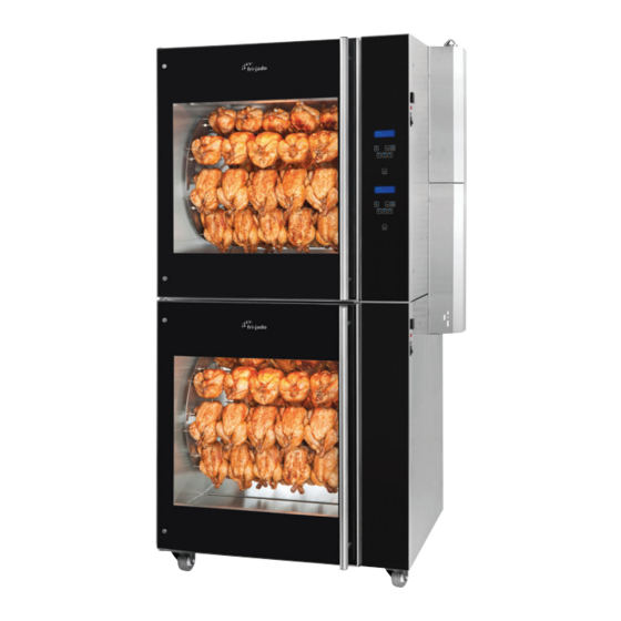
TDR 8 P GAS FIRED
ROTISSERIE OVEN
- NOTICE -
Model TDR 8 P Gas
Service Manual TDR8 P Gas form 9124023 rev. 01/2022
Model TDR 8+8 P Gas
Advertisement
Table of Contents

Subscribe to Our Youtube Channel
Related Manuals for Fri-Jado TDR 8 p gas


Summary of Contents for Fri-Jado TDR 8 p gas
- Page 1 SERVICE MANUAL TDR 8 P GAS FIRED ROTISSERIE OVEN MODELS TDR 8 p gas TDR 8+8 p gas Gas types: Model TDR 8 P Gas Natural Gas G20/25 Propane G31 (Butane G30) Model TDR 8+8 P Gas - NOTICE - This manual is prepared for the use of trained Service Technicians and should not be used by those not properly qualified.
- Page 2 EMPTY PAGE Page 2 Service Manual TDR8 P Gas form 9124023 rev. 01/2022...
- Page 3 TABLE OF CONTENTS Versions Version Issue date Remarks dd/mm/yy 10/2013 01/10/2013 First release. 01/2014 01/01/2014 Added reset and small textual changes. Exploded views and electric diagrams changed. 03/2014 01/03/2014 Working of rotisserie changed. Error 55 explanation. Small other changes. 11/2014 01/11/2014 New errors, various updates.
-
Page 4: Table Of Contents
Index ................................4 General technical data ..........................6 Technical data ............................6 Programming instructions for the TDR 8 P gas ..................8 The automatic cook correction ......................26 Removal and replacement of parts for the TDR 8 ................27 Right or left side panel ........................27 Top cover .............................. - Page 5 Fasteners ............................... 78 Electrical diagrams ..........................80 Circuit diagram TDR 8 P Gas from serial number 100097993 ............80 Wiring diagram TDR 8 P Gas from serial number 100097993 ............81 Circuit diagram TDR 8 P Gas Untill serial number 100097992 ............82 Wiring diagram TDR 8 P Gas Untill serial number 100097992 ............
-
Page 6: General Technical Data
GENERAL TECHNICAL DATA GENERAL TECHNICAL DATA This manual covers the TDR 8 P gas fired rotisserie ovens suitable for G 20/25 (natural gas), G 31 (Propane), G30 (Butane) and blend of Propane:Butane 60:40 till 100:0. • TDR 8 – Oven with eight spits ( 32 to 40 chickens ). - Page 7 GENERAL TECHNICAL DATA Tools • Standard set of tools. • Metric wrenches, sockets and hex socket key wrenches. • Multi-meter. • AC current clamp tester. • Temperature tester. • Insulation value tester (Megger). • Toxicity meter. • Gas pressure meter. •...
-
Page 8: Programming Instructions For The Tdr 8 P Gas
PROGRAMMING INSTRUCTIONS PROGRAMMING INSTRUCTIONS FOR THE TDR 8 P GAS OPERATING PANEL CHICKEN Display 85 1 Undo List On / Off Back Forward Rotor Function On / Off Switching the unit On / Off Undo Go back to previous menu... - Page 9 TDR-P Models OPERATION Buttons are lit when functional. 5.1. Operation of the rotisserie 1. Press Start. 2. Display shows Fri-Jado logo. 3. Display shows software version. Interface P Eco Version x.x.x 4. Display shows latest cooking Drumstick program. 5. Use the arrow buttons for program selection.
- Page 10 PROGRAMMING INSTRUCTIONS TDR-P Models 9. Pre-heat ready LOAD (unit returns a sound signal). Note: press OK or open the door to START stop the signal. Display shows the next step of the program. Note: Screen 9 and 11 alternate each 5 seconds. 10.
- Page 11 PROGRAMMING INSTRUCTIONS TDR-P Models 18. A reminder to measure the core Measure Core Temp. temperature appears. Note: Screen 17 and 18 alternate every 5 seconds. 19. (Optional, visible for 5 min.) request 2 Chicken for additional time (minutes) after Add time? opening the door.
- Page 12 PROGRAMMING INSTRUCTIONS OPERATION OPTIONS TDR-P Models 5.2. Operation options 5.2.1. To end a running program. 1. Press and hold start for 3 seconds. Stop? 2. Make a choice with the arrow buttons. Note: Select NO to abort ending the program. 3.
- Page 13 PROGRAMMING INSTRUCTIONS TDR-P Models 5.2.3. Check the remaining time in a program 1. Use the arrow buttons to show the 1 Chicken remaining time pro step. 230°C P123 0:05 2. Time left at step 1 1 Chicken (first digit blinks). 230°C P123 0:01 3.
- Page 14 PROGRAMMING INSTRUCTIONS TDR-P Models 6. Press the OK button to update the screen (automatically refreshed every 15 seconds). 7. Press List button to go back. 8. Display returns to the original 1 Chicken operating display. 180°C P123 0:20 5.2.5. Eco function Optional: only available when activated 1 Chicken in the service menu.
- Page 15 PROGRAMMING INSTRUCTIONS TDR-P Models 5.2.7. Display information 180°C 1. Display shows the programmed 0:20 temperature and time. 2. Press the list button. 3. Display shows after 3 seconds 1 Chicken cooking step + temperature + time. 180°C P123 0:20 Note: the current cooking step is underlined.
- Page 16 PROGRAMMING INSTRUCTIONS TDR-P Models PROGRAMMING MANAGER MENU 6.1. Manager menu items Programming Parameters Change pin Clock Pre-Heat Edit Preheat temperature Transfer Delete Holding Version Copy Holding temperature Cook correction* Reading recipes Eco function* Store recipes Language Big digits Sound preheat Sound step Sound done * Only visible when selected in the service menu.
- Page 17 PROGRAMMING INSTRUCTIONS TDR-P Models 6. Enter the User PIN code. Pin 0 - - - Give User PIN code Note: the original PIN code is 1111. The operator can change the User PIN code. 7. Use the arrow button to enter the PIN code.
- Page 18 PROGRAMMING INSTRUCTIONS TDR-P Models 15. The first available number is shown. Choose new number Note: use the arrow right button to select the next available number. 16. Press the OK button to confirm. 17. Enter the recipe name. 10 A-------------- for others Use the arrow button to change the character.
- Page 19 PROGRAMMING INSTRUCTIONS TDR-P Models 22. Press the OK button to confirm. 23. Set the “step 1” temperature. 10 Step 1 Starting with the first digit. Temp 1 - - °C 24. Use the arrow buttons to increase/decrease the value of the selected digit.
- Page 20 PROGRAMMING INSTRUCTIONS TDR-P Models 32. Press the OK button to confirm. 33. Set the second digit. 10 Step 1 Temp 215 °C Time 21 - 34. Press the OK button to confirm. 35. Set the last digit. 10 Step 1 Temp 215 °C Time 210 36.
- Page 21 PROGRAMMING INSTRUCTIONS TDR-P Models 40. When ready programming press the OK button to confirm. 41. Save the finished programs. 10 TEST Note: if the program is not saved all Save 1Disc changes are lost! 42. Press the OK button to confirm. 43.
- Page 22 PROGRAMMING INSTRUCTIONS TDR-P Models MANAGER MENU: PARAMETERS 6.3. Programming parameters 1. Press the list button. Pin * * * * 2. Enter your user PIN code. Give User PIN code 3. Press the OK button to confirm. 4. Press the arrow buttons to select MANAGER MENU Parameters.
- Page 23 PROGRAMMING INSTRUCTIONS TDR-P Models 9. Use the arrow buttons to select Language: English Change, Next or Previous. Change Next 1Previous Press back to enter the manager menu. 10. Use the arrow buttons to select Save and press the OK button to confirm. This is valid for software version V1.04-09 or higher.
- Page 24 PROGRAMMING INSTRUCTIONS TDR-P Models MANAGER MENU: CHANGE PINCODE 6.4. Change pin code 1. Manager menu. MANAGER MENU 2. Select Change Pin. Para Change Pin 1Clock 3. Press the OK button. 4. Enter the new pin code. Pin 0 0 0 0 5.
- Page 25 PROGRAMMING INSTRUCTIONS OPTIONS MANAGER MENU: USB TDR-P Models 6.8. 1. Manager menu. MANAGER MENU USB Programming 1Para. 2. Use the arrow buttons to select the USB function. 3. Screen shows the USB function. MANAGER MENU Place the USB stick into the USB- Edit slot.
-
Page 26: The Automatic Cook Correction
PROGRAMMING INSTRUCTIONS THE AUTOMATIC COOK CORRECTION The automatic cook correction facility will automaticly add or deduct time to the pro grammed cooking time in order to have constant cooking quality. After programming a new program, the first cooking process will be the “learning” process. It is recommended to do the first cook with a half load. -
Page 27: Removal And Replacement Of Parts For The Tdr 8
REMOVAL AND REPLACEMENT OF PARTS REMOVAL AND REPLACEMENT OF PARTS FOR THE TDR 8 WARNING: Disconnect the electrical power to the machine at the main circuit box. Place a tag on the circuit box indica- ting the circuit is being serviced. RIGHT OR LEFT SIDE PANEL 1. -
Page 28: Tumble Switch Reset
REMOVAL AND REPLACEMENT OF PARTS TUMBLE SWITCH RESET 1. Remove the right side panel and opera- ting panel according prior procedures. 2. Remove the wiring. 3. Remove the switch by pushing the clamps, on the inside, with a screw driver. 4. -
Page 29: Power And I/O Board
REMOVAL AND REPLACEMENT OF PARTS POWER AND I/O BOARD 1. Remove the right side panel according prior procedure. 2. Disconnect the wiring and flatcable on the board. 3. Remove the board from the clips by pìn- ching the clips. 4. Reverse the procedure to install. CPU BOARD Before changing the CPU board and display be sure to download (with a USB stick) or write... -
Page 30: Replacing Of Broken Buzzer
REMOVAL AND REPLACEMENT OF PARTS REPLACING OF BROKEN BUZZER 1. Remove the right side panel according prior procedure. 2. Remove the operating panel according prior procedure. 3. Stick connector of new buzzer in plug next to the existing broken buzzer (see white arrow). -
Page 31: Relay
REMOVAL AND REPLACEMENT OF PARTS RELAY 1. Remove the right side panel according prior procedure. 2. Loosen the clamp handle. 3. Gently remove the relay. 4. Reverse the procedure to install. Note: When placing a relay be sure the con- necting pins are in place. -
Page 32: Door Switch
REMOVAL AND REPLACEMENT OF PARTS DOOR SWITCH 1. Remove the right side panel and the ope- ration panel according prior procedures. 2. Remove the 2 screws that secure the switch and remove the switch. 2. Disconnect the wiring of the switch. 4. -
Page 33: Blower Motor
REMOVAL AND REPLACEMENT OF PARTS BLOWER MOTOR 1. Remove the right side panel, the top cover and the air suction plate according prior procedures. 2. Remove the wing nut on the fan blade and remove fan blade. (Left handed threads). 3. -
Page 34: Gas Mixture Blower
REMOVAL AND REPLACEMENT OF PARTS GAS MIXTURE BLOWER 1. Remove the right side panel and small top cover plate according prior procedures. 2. Remove the wiring from the top of the gas mixture blower. 3. Remove the silencer. 4. Remove the 4 nuts from the air inlet (A) and the 4 bolts with nuts from the gas inlet (B) and remove the gas mixture blo- wer. -
Page 35: Gas Control Block
REMOVAL AND REPLACEMENT OF PARTS GAS CONTROL BLOCK 1. Remove the right side panel and the gas burner safety control according prior pro- cedures. 2. Remove the nuts from the pipe clamps to create some clearance. 3. Remove the 4 screws on the top and bottom flange from the gas control block. -
Page 36: Drive Motor
REMOVAL AND REPLACEMENT OF PARTS DRIVE MOTOR 1. Remove the right side panel and rotor discs according prior procedure. 2. Disconnect the wiring of the motor. Check where the wire, marked A is connected. 3. Remove the screws that secure the fan co- ver and remove the cover. -
Page 37: Door Glass Inside
REMOVAL AND REPLACEMENT OF PARTS DOOR GLASS INSIDE 1. Lift the inside door upward out of the hinges and place it on a table. 2. Remove the nuts and rings on the pro- files of the door. 3. Remove the profiles from the glass. 4. -
Page 38: Working Of The Gas Fired Rotisserie
WORKING OF THE GAS FIRED ROTISSERIE WORKING OF THE GAS FIRED ROTISSERIE After plugging the unit in always first check the proper polarity for good ignition. After starting the rotisserie up with the on/off key the reset will light up. First press this switch for 2 seconds till the light is out. -
Page 39: Gas Technical Data
WORKING OF THE GAS FIRED ROTISSERIE GAS TECHNICAL DATA Inlet min pressure (Qn-Hi) Consumption Consumption Specific density type pressure max pressure (Qn-Hi) kg - cfm - LBS m3/h kg/m3 - lb/cf mbar - inch wc - PSI mbar - inch wc - PSI 20 - 8 - 0,3 17 - 7 - 0,25 1,0 - 0,80 - 2.2... -
Page 40: Sticker On Gas Burner Safety Control
WORKING OF THE GAS FIRED ROTISSERIE STICKER ON GAS BURNER SAFETY CONTROL 230V circuit 24V DC circuit 24V circuit: 230 V circuit: Tacho (nr.1) = White wire to speed regula- HD (nr. 1) = White wire to relay K1. On/off tion gas mixture blower. -
Page 41: Electrical Tests And Service Procedures
ELECTRICAL TESTS AND SERVICE PROCEDURES ELECTRICAL TESTS AND SERVICE PROCEDURES WARNING: Disconnect the electrical power to the machine at the main circuit box. Place a tag on the circuit box indica- ting the circuit is being serviced. PT1000 SENSOR TEST Note: When testing the resistance of the sen- Temperature Resistance Ω... -
Page 42: Control Location
ELECTRICAL TESTS AND SERVICE PROCEDURES CONTROL LOCATION CHICKEN Display 85 1 2 3 7 Undo List On / Off Back Forward Rotor Function On / Off Switching the unit On / Off Undo Go back to previous menu List Recipe / programming modus Forward One step ahead in setting Rotor... -
Page 43: Gas Block Honeywell Type Vk4115V - 2004
ELECTRICAL TESTS AND SERVICE PROCEDURES GAS BLOCK HONEYWELL TYPE VK4115V - 2004 Gas inlet: Inlet of gas after gas pressure reduction valve (max. 55 mbar or 22“ H2O). Pres- sure depending of gas type (see table on page 38). Gas outlet: Outlet of gas into gas mixture blower. Coils: 2 Coils for the gas valves. -
Page 44: Ignition/Ionization Set
ELECTRICAL TESTS AND SERVICE PROCEDURES IGNITION/IONIZATION SET When placing a new ignition/ionization set or for checking the adjustment of this set see drawing below. Here you can find the distance between the spark plug and the distance bet- ween the ignition pins and the burner bed and the distance between the ionisation pin and the burner bed. -
Page 45: Temporary Bridging Of Reset Switch
ELECTRICAL TESTS AND SERVICE PROCEDURES TEMPORARY BRIDGING OF RESET SWITCH For testing of the system, when reset switch could be malfunctioning, it is possible to bridge the reset switch by temporary, for 2 seconds, connecting both the grey and brown wires together. -
Page 46: Flue Gas Analyser
ELECTRICAL TESTS AND SERVICE PROCEDURES FLUE GAS ANALYSER With the flue gas analyser you can measure the exhaust gas on the rotisserie for toxicity. With the use of a Testo 330-1LL you get the following measurements: Testo 330-1LL V1.21 01297080 100035026 G 20 06.03.2014... -
Page 47: Gas Consumption
ELECTRICAL TESTS AND SERVICE PROCEDURES GAS CONSUMPTION With a flow meter you can measure the gas consumption/flow. See table on page 38. To get an accurat consumption you have to do a measurement of 3-5 minutes. During this pe- riod the rotisserie the rotisserie may not turn off. -
Page 48: Parameter Listing Tdr P
The service section is only accesible for qualified service technicians. The start up screen lists general information such as software version number, model name and Fri-Jado company logo. Please make sure you read the paragraph titled “adapting parameters” before changing parameters. - Page 49 PARAMETERS OPTIONS MANAGER MENU To enter the manager menu press and hold the List key. The manager section can be protect- ed by a seperate password. The standard number is “1111”, This password can be changed inside the manager menu. Manager Menu PROGRAMMING PARAMETERS...
- Page 50 PARAMETERS OPTIONS SERVICE MENU To enter the service menu press and hold the UNDO key for 5 seconds. The service section is by default protected with a default password of “4878”. READ SAVE << Page 50 Service Manual TDR8 P Gas form 9124023 rev. 01/2022...
-
Page 51: Manager Menu - Description Of The Submenus
PARAMETERS MANAGER MENU - DESCRIPTION OF THE SUBMENUS Menu section: Manager menu Parameter Description In this menu you can read recipies from the USB stick to the CPU board, or store programs from the CPU to the USB stick. Programming In this menu you can process the cooking programs. -
Page 52: Service Menu - Description Of The Submenus
PARAMETERS SERVICE MENU - DESCRIPTION OF THE SUBMENUS Menu section: Service menu Parameter Description In this menu you can read recIpies from the USB stick to the CPU board. And you can store recipies, parameters and LOG data to the USB stick. Function This menu allows access to the I/O test screen, Through this, several inputs and outputs of the machine can be monitored and toggled. - Page 53 PARAMETERS Parameter list Service menu Parameter Description Ecocook allowed This parameter alows the ecocook to be activated or not. Ecocook on yes means that the accumulated heat in the cavity will be used to cook the product and to save energy. Heating elements will not be activated during the last period of the last grilling step.
-
Page 54: Adapting Parameters
Only in case the unit has older software!! This software, supplied by Fri-Jado comes in a “zip” file with the version number of the software, for example “V1_4_09.zip”. The file needs to be copied on a USB stick. (disk “USB drive (F:)”... -
Page 55: Read And Store Recipies In The Manager Menu
PARAMETERS READ AND STORE RECIPIES IN THE MANAGER MENU Recipies can be read and stored from both the Manager menu and the Service menu. Recipies can only be read to, or stored from the CPU board by means of a memory stick. The transfer is always done out of a folder called “Programs”. -
Page 56: Read And Store Recipies And Parameters In The Service Menu
PARAMETERS READ AND STORE RECIPIES AND PARAMETERS IN THE SERVICE MENU Recipies can be read and stored from both the Manager menu and the Service menu. Recipies can only be read to, or stored from the CPU board by means of a memory stick. The transfer is always done out of a folder called “Programs”. - Page 57 PARAMETERS Parameters can only be read to, or stored from the CPU board by means of a memory stick. The transfer is always done out of a folder called “PARAMS”. This folder has to be placed direct on the memory stick and cannot be placed in another folder, otherwise it will not work.
-
Page 58: Default Parameters Eur
PARAMETERS DEFAULT PARAMETERS EUR Level 1 Level 2 Default Possibilities Information 1.05.2007 software version Manager 1111 Preheat allowed yes - no Preheat temp 50 - 250 Holding allowed yes - no Holding temp 50 - 250 Cook Correction yes - no Eco function yes - no Language... -
Page 59: General Troubleshooting List
TROUBLESHOOTING GENERAL TROUBLESHOOTING LIST TROUBLESHOOTING FOR THE TDR 8 GAS ROTISSERIES Symptom Possible causes No power to oven controls. 1. Main breaker open. 2. Fuse (125 mA) on power and I/O board burned. 3. Wiring loose. Main fuse or breaker blows. 1. - Page 60 TROUBLESHOOTING Symptom Possible causes No ignition of the gas in the bur- 1. Reset switch malfunction. ner (reset light is not burning). 2. Reset light on operation panel broken. 3. Reset on gas control block is on. Press this to reset. See page 44. 4.
-
Page 61: Error 55 Explanation
TROUBLESHOOTING ERROR 55 EXPLANATION Temp. increase °C / 2 minutes minutes Note: 1. Measuring starts 5 minutes after beginning of a heating step. 2. Duration is 5 periods of 2 minutes. 3. Measuring stops at 150°C/302°F or when temp. in cabinet is < 30°C than the set temperature. Necessary line currents: TDR8 with neutral 3x 16A. -
Page 62: Exploded Views & Partlists
EXPLODED VIEWS & PARTLISTS TDR 7 P GAS - ELECTRICAL PARTS FROM SERIAL NUMBER 100097688 J8-J13 Page 62 Service Manual TDR8 P Gas form 9124023 rev. 01/2022... - Page 63 EXPLODED VIEWS AND PARTLISTS Pos. Part number Description Pos. Part number Description Qty. Prio Qty. Prio 9151010 Connecting block 6-pole 9290343 control panel ass. 9171136 Glass lamp holder 9292040s CPU board + LCD 9140027 Blower + fanblade + 9292041 Keypad + short flatcable wingnut 9192400s Power &...
-
Page 64: Tdr 7 P Gas - Electrical Parts Until Serial Number 100097687
EXPLODED VIEWS AND PARTLISTS TDR 7 P GAS - ELECTRICAL PARTS UNTIL SERIAL NUMBER 100097687 Page 64 Service Manual TDR8 P Gas form 9124023 rev. 01/2022... - Page 65 EXPLODED VIEWS AND PARTLISTS Pos. Part number Description Pos. Part number Description Qty. Prio Qty. Prio 9290343 control panel ass. 9140027 Blower + fanblade + wingnut 9292040s CPU board + LCD 9293002s Gear motor, complete 9292041 Keypad + short flatcable with drive head 2000072 Fanblade Ø...
-
Page 66: Tdr 7 P Gas - Gas Parts
EXPLODED VIEWS AND PARTLISTS TDR 7 P GAS - GAS PARTS updated 2021 TDR8P Gas USA Page 66 Service Manual TDR8 P Gas form 9124023 rev. 01/2022... - Page 67 EXPLODED VIEWS AND PARTLISTS Pos. Part number Description Qty. Prio 9290550 Heat exchanger 9292106 Insulation, heat exchanger 9292109 Insulation board, heat exchanger 9290221 Insulation + sheet left ass. 9290222 Insulation + sheet right ass. 9070793 3d nut M6 9292107 Insulation exhaust pipe 9291018 Spring for insulation exhaust pipe 9281034...
-
Page 68: Tdr 7 P Gas - Doors
EXPLODED VIEWS AND PARTLISTS TDR 7 P GAS - DOORS Page 68 Service Manual TDR8 P Gas form 9124023 rev. 01/2022... - Page 69 EXPLODED VIEWS AND PARTLISTS Pos. Part number Description Qty. Prio 205 9298510s Door service side, ass., TDR7/8m 206 9298513s Door customer side, ass., TDR7/8m 207 9298512s Door inside, ass., TDR7/8m 215 9290410 Hinge, right 216 9290409 Hinge, left 217 9172054 Brass bearing 8 mm 218 9172122 Brass bearing 8 mm, adjusted...
-
Page 70: Tdr 7 P Gas - Rotor
EXPLODED VIEWS AND PARTLISTS TDR 7 P GAS - ROTOR 9292295 Untill serial number 100075953 Page 70 Service Manual TDR8 P Gas form 9124023 rev. 01/2022... - Page 71 EXPLODED VIEWS AND PARTLISTS Pos. Part number Description Qty. Prio 3701228 Capacitor 2.5 uF 9293002s Gear motor, complete with drive head 2000072 Fanblade Ø 150 mm, gearmotor 9073131 Seal ring, Teflon 9110797 Seal, silicon 9290444 Support plate, rotor motor 9172274 Rotorset ass.
-
Page 72: Tdr 7 P Gas - Stacking Parts
EXPLODED VIEWS AND PARTLISTS TDR 7 P GAS - STACKING PARTS Page 72 Service Manual TDR8 P Gas form 9124023 rev. 01/2022... - Page 73 EXPLODED VIEWS AND PARTLISTS Pos. Part number Description Qty. Prio 9292107 Insulation exhaust pipe 9291018 Spring for insulation exhaust pipe 9292120 Coupler tube + coupling 1/2" OD 9290551 Gas tube 1/2” with suspension 9171053 Elbow 1/2" 9173072 Tube 1/2" NPT 130mm 9292232 Exhaust elbow 9291106...
-
Page 74: Tdr 7 P Gas - Sheet Metal
EXPLODED VIEWS AND PARTLISTS TDR 7 P GAS - SHEET METAL Page 74 Service Manual TDR8 P Gas form 9124023 rev. 01/2022... - Page 75 EXPLODED VIEWS AND PARTLISTS Pos. Part number Description Qty. Prio ..Frame, ass. 9171125 Leg, rubber 50 mm 9294180 Side panel, left 9294018 Side panel, right 9294160 Top cover 9294032 Top plate 9294422 Cover, removeable 9174485 Cover, exhaust 9174408 Plate, air guide 9170568 Mounting plate, blowers 9290528...
-
Page 76: Tdr 7 P Gas - Insulation
EXPLODED VIEWS AND PARTLISTS TDR 7 P GAS - INSULATION Page 76 Service Manual TDR8 P Gas form 9124023 rev. 01/2022... - Page 77 EXPLODED VIEWS AND PARTLISTS Pos. Part number Description Qty. Prio 9292118 Insulation top, large 9292119 Insulation top, small 9293089 Insulation 141x21-28 9293090 Insulation 623x180 9293087 Insulation 327x730 9293085 Insulation 110x735 9293086 Insulation 210x730 9293088 Insulation 110x670 Service Manual TDR8 P Gas form 9124023 rev. 01/2022 Page 77...
-
Page 78: Fasteners
EXPLODED VIEWS AND PARTLISTS FASTENERS Pos. Part number Description Pos. Part number Description 800 4280107 Bolt M6x20 ZP 849 0142292 Nut M3 801 4289559 Lockwasher M6, serrated ZP 853 0141050 Screw M3x10, SS Cross recess pan head 802 4288321 Screw M5x16, SS socket button head. - Page 79 EXPLODED VIEWS AND PARTLISTS Pos. Part number Description Pos. Part number Description 895 0144359 Locknut M5, SS 949 0142975 896 4285408 Capnut M5, BNP 950 4285120 Screw M4x20, thread rolling 897 4288320 Screw M5x50, SS hexagonal 951 8071043 Nut M4, serrated ZP 898 9073987 Washer M8, SS ø8xØ25 952 6962187...
-
Page 80: Electrical Diagrams
ELECTRICAL DIAGRAMS CIRCUIT DIAGRAM TDR 8 P GAS FROM SERIAL NUMBER 100097993 Ionisation Pin Ignition BLOWERS TRAFO 230/12V R1 PT1000 OVEN TEMP. GAS BLOWER DOOR SWITCHES ROTOR CONTROLLED BY TOP UNIT LOCATED IN BOTTOM UNIT FAN (OPTION) GAS BURNER CONTROL Page 80 Service Manual TDR8 P Gas form 9124023 rev. -
Page 81: Wiring Diagram Tdr 8 P Gas From Serial Number 100097993
ELECTRICAL DIAGRAMS WIRING DIAGRAM TDR 8 P GAS FROM SERIAL NUMBER 100097993 Operator Side Customer Side HIGH LIMIT THERMOSTAAT 320 °C TB1/OR TB1/YE J8-2 93 12 BLOWER RG128 J8-1 RESET ~115V CONTROL ~230V J9-2 TB1/GN BU WH BK GY J9-1... -
Page 82: Circuit Diagram Tdr 8 P Gas Untill Serial Number 100097992
ELECTRICAL DIAGRAMS CIRCUIT DIAGRAM TDR 8 P GAS UNTILL SERIAL NUMBER 100097992 M4-PWR(115V) M4-1 M4-2 M4-5 M4-4 Ionisation Pin Ignition HIGH LIMIT CONTROLLED BY TOP UNIT LOCATED IN BOTTOM UNIT FAN (OPTION) BLOWERS GAS BURNER CONTROL TRAFO 230/12V ROTOR GAS BLOWER... -
Page 83: Wiring Diagram Tdr 8 P Gas Untill Serial Number 100097992
ELECTRICAL DIAGRAMS WIRING DIAGRAM TDR 8 P GAS UNTILL SERIAL NUMBER 100097992 X3-13/GY X3-5/BK K1-21 X3-1/WH M4-PWR(115V) X3-9/BU CB3-12 CB3-14 X1-3/GY X1-2/BN X1-7/YE M4-1 M4-2 X3-13/GY X3-5/BK X3-1/WH M4-5 M4-4 X3-9/BU ionisation X1-3/GY GREY BLUE YELLOW WHITE WHITE (24) 230V ONLY... -
Page 84: Circuit Diagram Tdr 8 P Gas Untill Serial Number 100080362
ELECTRICAL DIAGRAMS CIRCUIT DIAGRAM TDR 8 P GAS UNTILL SERIAL NUMBER 100080362 Page 84 Service Manual TDR8 P Gas form 9124023 rev. 01/2022... -
Page 85: Wiring Diagram Tdr 8 P Gas Untill Serial Number 100080362
ELECTRICAL DIAGRAMS WIRING DIAGRAM TDR 8 P GAS UNTILL SERIAL NUMBER 100080362 Service Manual TDR8 P Gas form 9124023 rev. 01/2022 Page 85... - Page 86 EMPTY PAGE Page 86 Service Manual TDR8 P Gas form 9124023 rev. 01/2022...
- Page 87 Service Manual TDR8 P Gas form 9124023 rev. 01/2022 Page 87...
- Page 88 Fri-Jado B.V. • P.O. Box 560 • 4870 AN • Etten-Leur • The Netherlands • tel +31 76 50 85 400 • fax +31 76 50 85 444 • info@frijado.com • www.frijado.com Page 88 Service Manual TDR8 P Gas form 9124023 rev. 01/2022...
Need help?
Do you have a question about the TDR 8 p gas and is the answer not in the manual?
Questions and answers