Table of Contents
Advertisement
Quick Links
SERVICE MANUAL
STG - ROTISSERIE OVEN MODELS
STW - WARMER MODELS
MODELS
Programmable controls
Warmers
WWW.FRIJADO.COM
This manual is prepared for the use of trained Service Technici-
ans and should not be used by those not properly qualified. If
you have attended training for this product, you may be quali-
fied to perform all the procedures in this manual.
This manual is not intended to be all encompassing. If you have
not attended a training for this product, you should read, in its
entirety, the repair procedure you wish to perform to determine
if you have the necessary tools, instruments and skills required
to perform the procedure. Procedures for which you do not have
the necessary tools, instruments and skills should be performed
by a trained technician.
Reproduction or other use of this Manual, without the express
written consent of Fri-Jado, is prohibited.
STG5 P
STG7 P
STW5
STW7
- NOTICE -
Service Manual STG5/7 STW5/7 form 9123659 rev. 03/2014
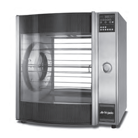
Model STG7 P
Advertisement
Table of Contents
Troubleshooting

Related Manuals for Fri-Jado STG


Summary of Contents for Fri-Jado STG
- Page 1 SERVICE MANUAL STG - ROTISSERIE OVEN MODELS STW - WARMER MODELS MODELS Programmable controls STG5 P STG7 P Warmers STW5 STW7 Model STG7 P - NOTICE - This manual is prepared for the use of trained Service Technici- ans and should not be used by those not properly qualified. If you have attended training for this product, you may be quali- fied to perform all the procedures in this manual.
- Page 2 TABLE OF CONTENTS Page 2 Service Manual STG5/7 STW5/7 form 9123659 rev. 03/2014...
- Page 3 TABLE OF CONTENTS Versions Version Issue date Remarks dd/mm/yy 10/2012 01/10/2012 General update. 03/2014 01/03/2014 Textual changes. Troubleshooting adaped. Exploded views modi- fied. Service Manual STG5/7 STW5/7 form 9123659 rev. 03/2014 Page 3...
-
Page 4: Table Of Contents
General technical data ..........................6 Technical data ............................6 Programming instructions for the STG 5 / STG 7 and STW 5 / STW 7 ........... 7 Optional settings for the STG 5 and STG 7 ..................... 9 Removal and replacement of parts for the STG 5 and STG 7 .............. 11 Right or left side panel ........................ - Page 5 TABLE OF CONTENTS Analytic troubleshooting list ......................... 30 Servicing and repairing the STG 5 and 7 rotisseries ................30 Servicing and repairing of the warmers STW 5 and 7 ..............34 Exploded views & partlists ........................36 STG 5 P - sheet metal work ......................... 36 STG 5 P - components ..........................
-
Page 6: General Technical Data
GENERAL TECHNICAL DATA GENERAL TECHNICAL DATA This manual covers the STG series rotisserie ovens and the STW series warmers. Ovens and warming cabinets come in two sizes. Ovens and cabinets will also be delivered in stacked versions. • STG 5 – Oven with five spits ( 15 to 20 chickens ) • STG 7 – Oven with seven spits ( 28 to 35 chickens ) • STW 5 Warming cabinet. -
Page 7: Programming Instructions For The Stg 5 / Stg 7 And Stw 5 / Stw 7
PROGRAMMING INSTRUCTIONS PROGRAMMING INSTRUCTIONS FOR THE STG 5 / STG 7 AND STW 5 / STW 7 DISPLAY AND KEYS Time display 8 8 8 2 1 0 8 8 8 8 0 0 3 0 Temperature Display Temperature hold indicator... - Page 8 PROGRAMMING INSTRUCTIONS SETTING ACTUAL TIME 15 PROGRAMS Press and hold Time of After the unit is swit- day key ched-on the time display 8 8 8 2 1 0 8 88 8 10 4 0 8 888 1 5pr indicates: 15PR Press Up or Down key Key 1: Release Time of day key...
-
Page 9: Optional Settings For The Stg 5 And Stg 7
Press Rotor key to start turning the rotor Press Rotor key again to stop Load the rotisserie with products OPTIONAL SETTINGS FOR THE STG 5 AND STG 7 INTERRUPTING ACTIVE PROGRAM SET ADDITIONAL BUZZER SIGNAL Press Rotor key Select a pre-defined program... - Page 10 PROGRAMMING INSTRUCTIONS SET PROGRAM END TIME DISPLAY SET TIME & TEMPERATURE Select a pre-defined Select a pre-defined program program 8 88 p 01 8 8 8 8 103 0 8 88 2 10 888 8 004 0 Press and hold the Pro- Press Cooking, Grilling gram end key or Temperature hold key...
-
Page 11: Removal And Replacement Of Parts For The Stg 5 And Stg 7
REMOVAL AND REPLACEMENT OF PARTS REMOVAL AND REPLACEMENT OF PARTS FOR THE STG 5 AND STG 7 WARNING: Disconnect the electrical power to the machine at the main circuit box. Place a tag on the circuit box indica- ting the circuit is being serviced. -
Page 12: Operating Panel
3. Remove the screw that secures the panel. 4. Remove the 2 bolts on the backside of the instrument panel (top and bottom side, only for the STG 7). 5. Remove the screws that secure the meat probe holder and remove the holder (if supplied). -
Page 13: Display
REMOVAL AND REPLACEMENT OF PARTS DISPLAY 1. Remove the right side panel according prior procedure. 2. Disconnect the flatcable on the display. 3. Remove the clip on the back, top left side that secures panel and frame. 4. Remove the nuts and washers on the backside of the display and remove the metal cover. -
Page 14: Quartz Lamp
REMOVAL AND REPLACEMENT OF PARTS QUARTZ LAMP Caution: Do not touch the glass with your hands. The moisture from your hands could affect the live span of the lamp. This moi- sture can be removed with alcohol while the lamp is cold. Note: Use a clean rag or paper towel to re- place the lamp. -
Page 15: High Limit Thermostat
2. Remove the suction and fan plate on the inside of the oven. 3. (STG 5 only) Remove the nut on the clamp STG7 and slide clamp towards yourself. Loosen the screw in the clamp that secures the probe and remove the probe. -
Page 16: Contactor
REMOVAL AND REPLACEMENT OF PARTS CONTACTOR 1. Remove the right side panel according prior procedure. 2. Disconnect the lead wires to the switch. 3. Push the locking tab down with a screw driver and lift the contactor out to remo- ve it from the mounting bracket. -
Page 17: Blower Motor Bottom Rotisserie (Stacked Stg)
6. Remove the drip trays from the upper oven. 7. Remove the bolts that secure the top plate (STG 5 must have a special top cover!) and remove the top plate. 8. Disconnect wiring of the motor. -
Page 18: Drive Motor
REMOVAL AND REPLACEMENT OF PARTS DRIVE MOTOR 1. Remove the right side panel and rotor discs according prior procedure. 2. Disconnect the wiring of the motor. Check where the wire, marked A is con- nected. 3. Remove the screws that secure the fan cover and remove the cover. -
Page 19: Door Adjustment (Left Side)
REMOVAL AND REPLACEMENT OF PARTS DOOR ADJUSTMENT (LEFT SIDE) 1. Remove the left side panel according prior procedure. 2. Loosen the nuts (A) of the upper hinge. The door must be closed. 3. Loosen the locknut (B) and adjust the bolt (C) in or out to adjust the door. -
Page 20: Door Outside
REMOVAL AND REPLACEMENT OF PARTS DOOR OUTSIDE 1. Lift the inner door out of the hinges and lay this aside. 2. Remove the left side panel according prior procedure. 3. Remove the 2 nuts behind the upper hinge and loosen the locknut according prior procedure. -
Page 21: Removal And Replacement Of Parts For The Stw 5 And Stw 7
REMOVAL AND REPLACEMENT OF PARTS REMOVAL AND REPLACEMENT OF PARTS FOR THE STW 5 AND STW 7 WARNING: Disconnect the electrical power to the machine at the main circuit box. Place a tag on the circuit box indica- ting the circuit is being serviced. BLOWER MOTOR 1. -
Page 22: Thermostat
REMOVAL AND REPLACEMENT OF PARTS THERMOSTAT 1. Remove the right side panel and the fan plate according prior procedures. 2. Remove the thermostat probe from the clamp inside the cavity (see arrow) and guide it outside through the opening. 3. Disconnect the wiring from the ther- mostat. -
Page 23: Heating Element
REMOVAL AND REPLACEMENT OF PARTS HEATING ELEMENT 1. Remove the right side panel, racks, bottom plate and the fan plate according prior procedures. 2. Disconnect the wiring from the element. 3. Remove the nuts and rings that secure the element and remove the element. 4. -
Page 24: Electrical Tests And Service Procedures
CONTACTOR, DRIVE MOTOR AND BLOWER TEST Note: When testing the resistance remove the wiring. Type Description Voltage Resistance Ω STG 5 + 7 Contactor 208 / 230 Resistance of coil (A1 - A2) ~ 52 STG 5 + 7 Drive motor... -
Page 25: Pt500 Sensor Test
ELECTRICAL TESTS AND SERVICE PROCEDURES PT500 SENSOR TEST 1. Remove the right side panel according Temperature Resistance prior procedure. °F °C ± 5 Ohms 2. Remove the wiring from the sensor. 3. Connect a temperature sensor to the probe for comparison. 4. -
Page 26: Keypad Test
STG 5 P: Change the wire 43 on the contactor with the wire 23 on the power board. Note: Wire 43 has to be extended. STG 7 P 3N~400V and 1N~230V: Change the wire 43 on the contactor with the wire 23 on the power board. -
Page 27: Control Location
ELECTRICAL TESTS AND SERVICE PROCEDURES CONTROL LOCATION THERMOMETER 1 ≈ 25°C 2 ≈ 40°C 3 ≈ 60°C THERMOSTAT DIAL 4 ≈ 80°C 5 ≈ 95°C Service Manual STG5/7 STW5/7 form 9123659 rev. 03/2014 Page 27... -
Page 28: General Troubleshooting List
TROUBLESHOOTING GENERAL TROUBLESHOOTING LIST TROUBLESHOOTING FOR THE STG 5 / 7 ROTISSERIES Symptom Possible causes No power to oven controls. 1. Main breaker open. 2. Fuse F1 burned. 3. Main switch malfunction. 4. Wiring loose. Main fuse or breaker blows. -
Page 29: Troubleshooting For The Stw 5 / 7 Warmers
TROUBLESHOOTING TROUBLESHOOTING FOR THE STW 5 / 7 WARMERS Symptom Possible causes No power to warmer controls. 1. Main breaker open. 2. Switch malfunction. 3. Wiring loose. Main fuse or breaker blows. 1. Wiring incorrectly. 2. Heating element or blower shorted. 3. -
Page 30: Analytic Troubleshooting List
TROUBLESHOOTING ANALYTIC TROUBLESHOOTING LIST SERVICING AND REPAIRING THE STG 5 AND 7 ROTISSERIES This is an analytic description for servicing and repairing all major parts of the rotisseries and warmers. It consists off 4 basic steps to recognize and solve the problems. These steps are: Symptoms. - Page 31 TROUBLESHOOTING Description of part Symptoms Possible causes Solving: checking/action PT-sensor Temperature indica- No connection between Check the wiring. tion on display runs wires. Check thin wire on sensor. up very fast and over the maximum of 250°C -482°F / 290°C - 550°F in 20 seconds) Temperature indica- Full contact between...
- Page 32 TROUBLESHOOTING Description of part Symptoms Possible causes Solving: checking/action Display and power No illumination on Wiring. Check the wiring. board display Check the power on the board. Fuse burned. Check the 63 mA fuse on the po- wer board. Replacing of fuse for 100 mA is permitted.
- Page 33 Coil malfunction. Check resistance of the coils. See table on page 24. Between blue and brown wire STG 7= 310Ω; STG 5= 310Ω Between blue and black wire STG 7= 320Ω; STG 5=190Ω Between brown and black wire STG 7= 630Ω; STG 5= 500Ω...
-
Page 34: Servicing And Repairing Of The Warmers Stw 5 And 7
TROUBLESHOOTING SERVICING AND REPAIRING OF THE WARMERS STW 5 AND 7 Description of part Symptoms Possible causes Solving: checking/action Outside door Broken glass Slamming of door. Give instruction to operator. Fastening bolts and nuts Tighten all fastenings. are loose. No sealing ring between Mount new glass with sealing steel and glass. - Page 35 TROUBLESHOOTING Description of part Symptoms Possible causes Solving: checking/action Blower Blower doesn’t run Wiring. Check the wiring. Check the power on the blower. Coil malfunction. Check resistance of the coils.See table on page 24. Between blue and brown wire= 310Ω Between blue and black wire= 320Ω...
-
Page 36: Exploded Views & Partlists
EXPLODED VIEWS AND PARTLISTS EXPLODED VIEWS & PARTLISTS STG 5 P - SHEET METAL WORK Page 36 Service Manual STG5/7 STW5/7 form 9123659 rev. 03/2014... - Page 37 EXPLODED VIEWS AND PARTLISTS Item Part num- Qty. Description ..Frame, ass. 9171125 Leg, rubber 50 mm 9011260 Leg, rubber 40 mm (till 01-01-2008) 9170428 Side panel, left 9170532 Side panel, right 4288322 Screw M5 x 10, SS socket button head 9110810 Indication plate 9174060...
-
Page 38: Stg 5 P - Components
EXPLODED VIEWS AND PARTLISTS STG 5 P - COMPONENTS 48-1 48-2 40-1 40-2 40-1-1 64-5 64-4 64-3 64-2 64-1 52-6 52-8 52-2 52-12 52-5 52-10 52-7 52-4 52-9 52-3 52-1 D-0093-02 52-11 Page 38 Service Manual STG5/7 STW5/7 form 9123659 rev. 03/2014... - Page 39 M6x20 SS PT 500 40-2 9174369 Rotor disc 3 mm (5-holes), 9151010 Connecting block stainless steel 9172040 Name plate Fri-Jado, 9172062 Steel bearing, 12 mm foil + backplate 9010549 Meatfork, stainless steel 9173017 Main power knob assembly 9172222 Meatfork, coated...
-
Page 40: Stg 5 P - Doors
EXPLODED VIEWS AND PARTLISTS STG 5 P - DOORS 81-6 81-7 81-8 81-4 82-3 81-9 82-4 82-5 81-3 81-2 82-1 80-6 80-4 80-8 80-7 80-9 81-5 82-2 81-1 81.C 80-3 80-2 80-5 80-1 80.S 81-19 81-7 81-18 81-20 81-12 81-13... - Page 41 EXPLODED VIEWS AND PARTLISTS Item Part number Description Item Part number Description 80.S 9179859S Door service side, ass. 9179855S Door inside, ass. 80-1 9170441 Hinge profile 82-1 9170442 Hinge profile 80-2 4288321 Screw M5 x 16, SS socket 82-2 0211520 Bolt M5 x 12 ss hexagon head button head 82-3...
-
Page 42: Stg 7 P - Sheet Metal Work
EXPLODED VIEWS AND PARTLISTS STG 7 P - SHEET METAL WORK D-0096-01 Page 42 Service Manual STG5/7 STW5/7 form 9123659 rev. 03/2014... - Page 43 EXPLODED VIEWS AND PARTLISTS Item Part number Qty. Description ..Frame, ass. 9171125 Leg, rubber 50 mm 9011260 Leg, rubber 40 mm (till 01-01-2008) 9170419 Side panel, left 9170531 Side panel, right 4288322 Screw M5 x 10, SS socket button head 9110810 Indication plate 9174099...
-
Page 44: Stg 7 P - Components
EXPLODED VIEWS AND PARTLISTS STG 7 P - COMPONENTS 49-1 49-2 40-1 40-2 40-3 40-4 40-5 40-6 66-5 66-4 66-3 66-2 66-1 50-6 50-8 50-2 50-12 50-5 50-10 50-7 50-4 50-9 50-3 50-1 D-0095-02 50-11 Page 44 Service Manual STG5/7 STW5/7 form 9123659 rev. 03/2014... - Page 45 Mounting plate, lamp 9070094 Temperature sensor holder 9151010 Connecting block 9040023 Heating element 230 V, 2100 W 9172040 Name plate Fri-jado, foil + backplate 9044653 Heating element 230 V, 3100 W 9173017 Main power knob assembly 9110023 Lamp holder, cap +...
-
Page 46: Stg 7 P - Doors
EXPLODED VIEWS AND PARTLISTS STG 7 P - DOORS 81-6 81-7 81-8 81-4 81-9 82-3 82-4 82-5 81-3 81-2 82-1 80-6 80-4 80-8 80-7 80-9 81-5 82-2 81-1 81.C 80-3 80-2 80-5 80-1 80.S 81-19 81-7 81-18 81-20 81-12 81-13... - Page 47 EXPLODED VIEWS AND PARTLISTS Item Part number Qty. Description Item Part number Qty. Description 80.S 9179850S Door service side, ass. 9179852S Door inside, ass. 80-1 9170422 Hinge profile 82-1 9170423 Hinge profile 80-2 4288321 Screw M5 x 16, SS socket 82-2 0211520 Bolt M5 x 12 ss hexagon...
-
Page 48: Stw 5 - Sheet Metal Work
EXPLODED VIEWS AND PARTLISTS STW 5 - SHEET METAL WORK D-0050-01 Page 48 Service Manual STG5/7 STW5/7 form 9123659 rev. 03/2014... - Page 49 EXPLODED VIEWS AND PARTLISTS Item Part number Qty. Description ..Frame, ass. 9170428 Side panel, left 9170480 Side panel, right 9110810 Indication plate 4288322 Screw M5 x 10, SS socket button head 9174060 Cap, top 9170432 Side panel, top 9174092 Reinforcement, side plate, right 9174061 Cover, removable...
-
Page 50: Stw 5 - Components
EXPLODED VIEWS AND PARTLISTS STW 5 - COMPONENTS 45-7 45-5 45-6 45-8 45-4 45-3 45-2 44-5 44-7 44-6 44-8 44-4 45.C 45-1 44-3 44-2 44-1 44-4 45-18 45-6 45-17 45-19 45-11 59-1 45-12 44.S 45-13 50-1 58-5 58-4 50-2 58-3 58-2 58-1 44-6... - Page 51 9110030 Capacitor 1,5 mF 44-7 4311110 Washer 9091383 Connecting cable with plug 44-8 0144359 Nut, self locking M5 9172040 Name plate Fri-jado, foil + 44-9 4288320 Screw M5x45 SS backplate 44-10 9174680 Washer 9173057 Main power/thermostat knob assembly 44-11 9070141...
-
Page 52: Stw 7 - Sheet Metal Work
EXPLODED VIEWS AND PARTLISTS STW 7 - SHEET METAL WORK D-0051-01 Page 52 Service Manual STG5/7 STW5/7 form 9123659 rev. 03/2014... - Page 53 EXPLODED VIEWS AND PARTLISTS Item Part num- Qty. Description ..Frame 9170419 Side panel, left 9170479 Side panel, right 9110810 Indication plate 4288322 Screw M5 x 10, SS socket button head 9174045 Cap, top 9170421 Side panel, top 9174046 Reinforcement, side plate, right 9174005 Cover, removable 9174048...
-
Page 54: Stw 7 - Components
EXPLODED VIEWS AND PARTLISTS STW 7 - COMPONENTS 45-7 45-5 45-6 45-8 45-4 45-3 44-5 44-7 45-2 44-6 44-8 44-4 45.C 44-3 45-1 44-2 44-1 44-4 45-18 45-6 45-17 45-19 45-11 59-1 45-12 45-13 44.S 50-1 58-5 58-4 50-2 58-3 58-2 58-1 44-6... - Page 55 9110030 Capacitor 1,5 mF 44-7 4311110 Washer 9091383 Connecting cable with plug 44-8 0144359 Nut, self locking M5 9172040 Name plate Fri-jado, foil + 44-9 4288320 Screw M5x45 SS backplate 44-10 9174680 Washer 9173057 Main power/thermostat knob assembly 44-11 9070141...
-
Page 56: Cuircuit Diagram Stg 5 P
ELECTRICAL DIAGRAMS CUIRCUIT DIAGRAM STG 5 P ELECTRICAL DIAGRAMS Page 56 Service Manual STG5/7 STW5/7 form 9123659 rev. 03/2014... -
Page 57: Wiring Diagram Stg 5 P
ELECTRICAL DIAGRAMS WIRING DIAGRAM STG 5 P Service Manual STG5/7 STW5/7 form 9123659 rev. 03/2014 Page 57... -
Page 58: Wiring Diagram Stg 5 P (Until Serial Number 100052500)
ELECTRICAL DIAGRAMS WIRING DIAGRAM STG 5 P (UNTIL SERIAL NUMBER 100052500) Page 58 Service Manual STG5/7 STW5/7 form 9123659 rev. 03/2014... -
Page 59: Cuircuit Diagram Stg 7 P
ELECTRICAL DIAGRAMS CUIRCUIT DIAGRAM STG 7 P Service Manual STG5/7 STW5/7 form 9123659 rev. 03/2014 Page 59... -
Page 60: Wiring Diagram Stg 7 P
ELECTRICAL DIAGRAMS WIRING DIAGRAM STG 7 P Page 60 Service Manual STG5/7 STW5/7 form 9123659 rev. 03/2014... -
Page 61: Wiring Diagram Stg 7 P (Until Serial Number 100052500)
ELECTRICAL DIAGRAMS WIRING DIAGRAM STG 7 P (UNTIL SERIAL NUMBER 100052500) Service Manual STG5/7 STW5/7 form 9123659 rev. 03/2014 Page 61... -
Page 62: Cuircuit Diagram Stw 5
ELECTRICAL DIAGRAMS CUIRCUIT DIAGRAM STW 5 Page 62 Service Manual STG5/7 STW5/7 form 9123659 rev. 03/2014... -
Page 63: Wiring Diagram Stw 5
ELECTRICAL DIAGRAMS WIRING DIAGRAM STW 5 Service Manual STG5/7 STW5/7 form 9123659 rev. 03/2014 Page 63... -
Page 64: Cuircuit Diagram Stw 7
ELECTRICAL DIAGRAMS CUIRCUIT DIAGRAM STW 7 Page 64 Service Manual STG5/7 STW5/7 form 9123659 rev. 03/2014... -
Page 65: Wiring Diagram Stw 7
ELECTRICAL DIAGRAMS WIRING DIAGRAM STW 7 Service Manual STG5/7 STW5/7 form 9123659 rev. 03/2014 Page 65... - Page 66 Service Manual STG5/7 STW5/7 form 9123659 rev. 03/2014 Page 66...
- Page 67 Service Manual STG5/7 STW5/7 form 9123659 rev. 03/2014 Page 67...
- Page 68 Fri-Jado B.V. • P.O. Box 560 • 4870 AN • Etten-Leur • The Netherlands • tel +31 76 50 85 400 • fax +31 76 50 85 444 • info@frijado.com • www.frijado.com...
Need help?
Do you have a question about the STG and is the answer not in the manual?
Questions and answers