Table of Contents
Advertisement
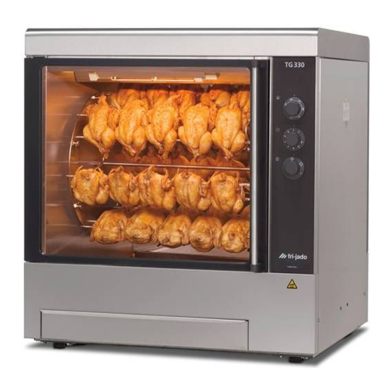
SERVICE MANUAL
TG - ROTISSERIE OVEN MODELS
MODELS
Manual controls
WWW.FRIJADO.COM
TG50 H
TG110 H
TG330 H
TG550 H
This manual is prepared for the use of trained Service Technicians and
should not be used by those not properly qualified. If you have attended
a trianing for this product, you may be qualified to perform all the proce-
This manual is not intended to be all encompassing. If you have not
attended a training for this product, you should read, in its entirety, the
repair procedure you wish to performto determine if you have the neces-
sary tools, instruments and skills required to perform the procedure.
Procedures for which you do not have the necessary tools, instruments
and skills should be performed by a trained technician.
Reproduction or other use of this Manual, without the express written
consent of Fri-Jado, is prohibited.
- NOTICE -
dures in this manual.
Service Manual TG50/110/330/550 H form 9123660 rev. 04/2007
Model TG330 H
Advertisement
Table of Contents

Subscribe to Our Youtube Channel
Related Manuals for Fri-Jado TG50 H


Summary of Contents for Fri-Jado TG50 H
- Page 1 Procedures for which you do not have the necessary tools, instruments and skills should be performed by a trained technician. Reproduction or other use of this Manual, without the express written consent of Fri-Jado, is prohibited. Service Manual TG50/110/330/550 H form 9123660 rev. 04/2007 WWW.FRIJADO.COM...
- Page 2 EMPTY PAGE Page 2 Service Manual TG50/110/330/550 H form 9123660 rev. 04/2007...
-
Page 3: Table Of Contents
Heating element test ............................24 Control location .............................24 Changing Quartz light functions ........................25 Troubleshooting the TG110/330/550 H Rotisserie ..............26 Troubleshooting the TG50 H Rotisserie ..................26 Servicing and repairing ......................27 TG 110 - 330 and 550 H ..........................27 TG 50 H ................................31 Exploded views &... -
Page 4: General Technical Data
GENERAL TECHNICAL DATA GENERAL TECHNICAL DATA This manual covers the TG series rotisserie ovens 50-110-330-550 H. These are manual controlled ovens. • TG 50 H – Oven with three spits ( 9 chickens ). • TG 110 H – Oven with four spits ( 16 chickens ). •... -
Page 5: Removal And Replacement Of Parts For The Tg50/Tg110/Tg330/Tg550 H
REMOVAL AND REPLACEMENT OF PARTS REMOVAL AND REPLACEMENT OF PARTS FOR THE TG50/TG110/TG330/TG550 H WARNING: Disconnect the electrical power to the machine at the main circuit box. Place a tag on the circuit box indicating the circuit is being serviced. RIGHT OR LEFT SIDE PANEL TG330/550 1. -
Page 6: Top Cover Tg330/550
REMOVAL AND REPLACEMENT OF PARTS TOP COVER TG330/550 1. Remove the right side panel according prior procedure. 2. Remove the bolts and nuts on the inside of the top cover. 3. Remove the screws on the top cover and remove the cover. 4. -
Page 7: Left Side Panel Tg110
REMOVAL AND REPLACEMENT OF PARTS LEFT SIDE PANEL TG110 1. Remove the right side panel and the top co- ver according prior procedures. 2. Remove the wing nuts at the top of the left side panel. 3. Allow the panel to slide down and remove it from the unit. -
Page 8: Control Panel Tg110
REMOVAL AND REPLACEMENT OF PARTS CONTROL PANEL TG110 1. Remove the right side panel according prior procedures. 2. Remove the knobs according prior procedu- res. 3. Remove the screws that secure the panel. 4. Remove the wing nuts and bolts on the back- side that secure the panel and remove the panel. -
Page 9: Electric Panel Tg330/550
REMOVAL AND REPLACEMENT OF PARTS ELECTRIC PANEL TG330/550 1. Remove the knobs according prior proce- dure. 2. Remove the screws on the front side that secure the panel. 3. Remove the cover box on the electric panel according prior procedure. 4. -
Page 10: High Limit Thermostat
REMOVAL AND REPLACEMENT OF PARTS HIGH LIMIT THERMOSTAT 1. Remove the right side panel according prior procedure. 2. (TG 330-550 only) Remove the suction and fan plate on the inside of the oven. 3. (TG 110 only) Remove the nut on the clamp and slide clamp towards yourself. -
Page 11: Thermostat Tg110
REMOVAL AND REPLACEMENT OF PARTS THERMOSTAT TG110 1. Remove the control panel according prior procedure. 2. Remove the nut on the clamp and slide clamp towards yourself. Loosen the screw in the clamp that secures the probe and remove the probe. 3. -
Page 12: Timer Tg50
REMOVAL AND REPLACEMENT OF PARTS TIMER TG50 1. Remove the control panel according prior procedure. 2. Remove the screws on the electric panel that secure the timer. 3. Remove the timer and disconnect the wiring. 4. Reverse the procedure to install. CONTACTOR 1. -
Page 13: Blower Motor Bottom Rotisserie (Tg550 Only)
REMOVAL AND REPLACEMENT OF PARTS BLOWER MOTOR BOTTOM ROTISSERIE (TG550 ONLY) 1. Remove the right side panel according prior procedures. 2. Remove the rotor discs, suction and fan plate in the bottom oven. 3. Remove the wing nut on the fan blade and remove fan blade. -
Page 14: Heating Element Tg110/330/550
REMOVAL AND REPLACEMENT OF PARTS HEATING ELEMENT TG110/330/550 1. Remove the rotor discs, right side panel, suction and fan plate according prior proce- dures. 2. Disconnect the wiring from the element. TG330/550 3. Remove the mounting nut. 4. Remove the element from the mounting clip and pull it from the wall. -
Page 15: Drive Motor Tg330/550
REMOVAL AND REPLACEMENT OF PARTS DRIVE MOTOR TG330/550 1. Remove the right side panel and rotor discs according prior procedures. 2. Disconnect the wiring of the motor. Check where the wire, marked A is connected. 3. Remove the screws that secure the fan cover and remove the cover. -
Page 16: Drive Motor Tg50
REMOVAL AND REPLACEMENT OF PARTS DRIVE MOTOR TG50 1. Remove the left side panel according prior procedure. 2. Remove the screws that hold the back panel and remove this panel. 3. Remove the 4 screws on the bottom side that secure the motor. -
Page 17: Door Adjustment Tg110
REMOVAL AND REPLACEMENT OF PARTS DOOR ADJUSTMENT TG110 1. Remove the left side panel according prior procedure. 2a. Loosen the 2 bolts on the hinge to adjust the door in horizontal way. 2b. Loosen the 4 bolts on the reinforcement plate to adjust the door in the depth. -
Page 18: Changing Door Tg330/550
REMOVAL AND REPLACEMENT OF PARTS CHANGING DOOR TG330/550 1. Open the door and remove the bolts that secure the hinge plate, while supporting the door, and remove the plate. 2. Lift the door to remove the lower hinge pin from the bearing. 3. -
Page 19: Reversal Of Grill Door Tg330/550
REMOVAL AND REPLACEMENT OF PARTS REVERSAL OF GRILL DOOR TG330/550 1. Follow procedure of “changing door” point 1 and 2. 2. Drill a hole of 10 mm in the pilot hole on the handle side of the frame and replace the bearing (part nr.0602072). -
Page 20: Reversal Of Grill Door Tg50
REMOVAL AND REPLACEMENT OF PARTS REVERSAL OF GRILL DOOR TG50 1. Follow procedure of “changing door”. 2. Drill a hole of 10 mm in the pilot hole on the handle side of the frame and replace the bearing (part nr.0602072). Replace the bearing (part nr. -
Page 21: Changing Complete Drain Plug
REMOVAL AND REPLACEMENT OF PARTS CHANGING COMPLETE DRAIN PLUG 1. Open fat drawer and loosen the plug by me- ans of the wing nut. 2. Loosen the setscrew of the wing nut on the brass ring. 3. Remove drain plug by unscrewing the wing nut. -
Page 22: Adjusting Chain Tension Tg50 (Motor Side)
REMOVAL AND REPLACEMENT OF PARTS ADJUSTING CHAIN TENSION TG50 (MOTOR SIDE) 1. Remove the left side panel according prior procedure. 2. Loosen the 2 screws that secure the chain stretcher. 3. Adjust the chain tension with the bolt on top of the chain stretcher. -
Page 23: Adjusting/Aligning Rotor Discs Tg50
REMOVAL AND REPLACEMENT OF PARTS ADJUSTING/ALIGNING ROTOR DISCS TG50 1. Remove the left side panel according prior procedure. 2. Loosen the clamp nut on the front shaft. 3. Put a spit between the rotor discs and align the discs by turning the right side disk. 4. -
Page 24: Electrical Tests
ELECTRICAL TESTS AND SERVICE PROCEDURES ELECTRICAL TESTS WARNING: Disconnect the electrical power to the machine at the main circuit box. Place a tag on the circuit box indicating the circuit is being serviced. HEATING ELEMENT TEST Type Wattage/Voltage Resistance Ω Current A Note: When testing the resi- -5% + 10%... -
Page 25: Changing Quartz Light Functions
ELECTRICAL TESTS AND SERVICE PROCEDURES CHANGING QUARTZ LIGHT FUNCTIONS For the standard rotisseries (with doors on both sides) the Quartz light on customer side is always on during the process and the light on service side switches on and off with the heating elements. In some cases it is desirable that the lights work the other way around. -
Page 26: Troubleshooting The Tg110/330/550 H Rotisserie
3. Wiring loose. Oven temperature does not reach desired 1. Thermostat malfunction. temperature. 2. Heater(s) inoperative. 3. Incorrect voltage line. TROUBLESHOOTING THE TG50 H ROTISSERIE Symptom Possible causes Drive head does not run. 1. Main fuse open. 2. Capacitor malfunction. -
Page 27: Servicing And Repairing
TROUBLESHOOTING SERVICING AND REPAIRING TG 110 - 330 AND 550 H This is an analytic description for servicing and repairing all major parts of the rotisseries. It consists off 4 basic steps to recognize and solve the problems. These steps are: Symptoms. - Page 28 TROUBLESHOOTING Description of part Symptoms Possible causes Solving: checking/action Timer No functions of oven are Wiring. Check the wiring on the working switch. Check the power on the switch. Malfunction of the timer. Check functions after connecting a new timer. Grilling process is wor- Malfunction of the timer.
- Page 29 TROUBLESHOOTING Description of part Symptoms Possible causes Solving: checking/action Drive motor Motor doesn’t run Wiring. Check the wiring. Check the power to the motor. Coil malfunction Check resistance of the coils. TG 330 and 550: Between whiteA and white wire ±234Ω Between whiteA and brown wire ±117Ω...
- Page 30 TROUBLESHOOTING Description of part Symptoms Possible causes Solving: checking/action Blower TG 330-550 Blower doesn’t run Wiring. Check the wiring. Check the power on the blower. Coil malfunction. Check resistance of the coils. Between blue and brown wire = ±310Ω Between blue and black wire = ±320Ω...
- Page 31 TROUBLESHOOTING Description of part Symptoms Possible causes Solving: checking/action Blower TG 110 Blower doesn’t run Wiring. Check the wiring. Check the power on the blower. Coil malfunction. Check resistance of the coils. Between the 2 black wires = ±115 Ω. Blower stops during pro- Coil overheated, thermis- Check cooling circuit of...
- Page 32 TROUBLESHOOTING Description of part Symptoms Possible causes Solving: checking/action Thermostat Oven temperature differs Wiring. Check the wiring. from temperature setting Thermostat malfunction. Check if the thermostat is making contact. Thermostat probe not in Check the position of the right position. thermostat probe.
- Page 33 TROUBLESHOOTING Description of part Symptoms Possible causes Solving: checking/action Capacitor Drive motor doesn’t work Wiring. Check the wiring. Capacitor malfunction. Check function after con- necting a new capacitor. Checking of capacitor: Discharge capacitor with screwdriver. Set meter on MΩ and connect the pins of the meter on contacts, value runs up.
- Page 34 TROUBLESHOOTING Description of part Symptoms Possible causes Solving: checking/action Drive motor Motor doesn’t run Wiring. Check the wiring. Check the power to the motor. Coil malfunction Check resistance of the coils. Between whiteA and white wire ±240Ω Between whiteA and black wire ±120Ω...
-
Page 35: Exploded Views & Partlists
EXPLODED VIEWS AND PARTLISTS EXPLODED VIEWS & PARTLISTS Page 35 Service Manual TG50/110/330/550 H form 9123660 rev. 04/2007... - Page 36 EXPLODED VIEWS AND PARTLISTS Page 36 Service Manual TG50/110/330/550 H form 9123660 rev. 04/2007...
- Page 37 EXPLODED VIEWS AND PARTLISTS Page 37 Service Manual TG50/110/330/550 H form 9123660 rev. 04/2007...
- Page 38 EXPLODED VIEWS AND PARTLISTS Page 38 Service Manual TG50/110/330/550 H form 9123660 rev. 04/2007...
- Page 39 EXPLODED VIEWS AND PARTLISTS Page 39 Service Manual TG50/110/330/550 H form 9123660 rev. 04/2007...
- Page 40 EXPLODED VIEWS AND PARTLISTS Page 40 Service Manual TG50/110/330/550 H form 9123660 rev. 04/2007...
- Page 41 EXPLODED VIEWS AND PARTLISTS Page 41 Service Manual TG50/110/330/550 H form 9123660 rev. 04/2007...
- Page 42 EXPLODED VIEWS AND PARTLISTS Page 42 Service Manual TG50/110/330/550 H form 9123660 rev. 04/2007...
- Page 43 EXPLODED VIEWS AND PARTLISTS Page 43 Service Manual TG50/110/330/550 H form 9123660 rev. 04/2007...
- Page 44 EXPLODED VIEWS AND PARTLISTS Page 44 Service Manual TG50/110/330/550 H form 9123660 rev. 04/2007...
- Page 45 EXPLODED VIEWS AND PARTLISTS Page 45 Service Manual TG50/110/330/550 H form 9123660 rev. 04/2007...
- Page 46 EXPLODED VIEWS AND PARTLISTS Page 46 Service Manual TG50/110/330/550 H form 9123660 rev. 04/2007...
- Page 47 EXPLODED VIEWS AND PARTLISTS Page 47 Service Manual TG50/110/330/550 H form 9123660 rev. 04/2007...
-
Page 48: Electrical Diagrams
EXPLODED VIEWS AND PARTLISTS ELECTRICAL DIAGRAMS Page 48 Service Manual TG50/110/330/550 H form 9123660 rev. 04/2007... - Page 49 EXPLODED VIEWS AND PARTLISTS Page 49 Service Manual TG50/110/330/550 H form 9123660 rev. 04/2007...
- Page 50 EXPLODED VIEWS AND PARTLISTS Page 50 Service Manual TG50/110/330/550 H form 9123660 rev. 04/2007...
- Page 51 EXPLODED VIEWS AND PARTLISTS Page 51 Service Manual TG50/110/330/550 H form 9123660 rev. 04/2007...
- Page 52 EXPLODED VIEWS AND PARTLISTS Page 52 Service Manual TG50/110/330/550 H form 9123660 rev. 04/2007...
- Page 53 EXPLODED VIEWS AND PARTLISTS Page 53 Service Manual TG50/110/330/550 H form 9123660 rev. 04/2007...
- Page 54 Fri-Jado B.V. • P.O. Box 560 • 4870 AN • Etten-Leur • The Netherlands • tel +31 76 50 85 400 • fax +31 76 50 85 444 • info@frijado.com • www.frijado.com Service Manual TG50/110/330/550 H form 9123660 rev. 04/2007...
Need help?
Do you have a question about the TG50 H and is the answer not in the manual?
Questions and answers